1. Introduction
Parallel mechanisms (PMs) are widely used in industries such as manufacturing, aerospace, and medical surgery due to their advantages of high speed, high stiffness, and large load-carrying capacity [Reference Essomba, Laribi, Zeghloul and Poisson1–Reference Refaat, Hervé, Nahavandi and Trinh3]. However, their limited workspace and the presence of singularities hinder broader applications [Reference Zhang, Ye and Li4–Reference Yang and Li7]. The introduction of redundancy can effectively eliminate singularities, expand the workspace, and enhance the overall performance of the mechanisms, thereby endowing redundant PMs with strong application potential [Reference Luces, Mills and Benhabib8–Reference Gosselin and Schreiber10].
Redundant PMs can be further categorized into two types: redundantly actuated PMs and kinematically redundant PMs [Reference Xie, Liu and Wang11]. Introducing redundant actuation in PMs does not alter their degrees of freedom (DOF) and offers advantages such as avoiding singular configurations and enhancing load-carrying capacity. However, the internal forces generated by antagonistic interactions between limbs make control more challenging [Reference Liu, Yao, Li and Zhao12–Reference Wang, Li and Sun13]. In contrast, kinematically redundant PMs introduce additional DOFs, resulting in a total number of DOF greater than that of the moving platform. When the moving platform assumes a specific position and orientation, the mechanism has multiple inverse kinematics solutions [Reference Arsenault, Boudreau and Nokleby14], enabling it to perform internal motions that effectively avoid or eliminate singular configurations and expand the workspace [Reference Lacombe and Gosselin15–Reference Lacombe and Gosselin16]. Kotlarski et al. [Reference Kotlarski, Abdellatif, Ortmaier and Heimann17] demonstrated the effectiveness of introducing kinematic redundancy for singularity avoidance in 3-RRR and 3-RPR mechanisms. Wen and Gosselin et al. [Reference Wen, Nguyen, Harton, Laliberte and Gosselin18–Reference Gosselin and Schreiber19] validated the workspace expansion capabilities of two types of (6 + 3)-DOF kinematically redundant PMs, particularly highlighting their significant advantages in enlarging the orientational workspace.
Existing research on kinematically redundant PMs primarily focuses on configuration design, kinematic analysis, and trajectory planning [Reference Wen and Gosselin20–Reference Schreiber and Gosselin22]. However, limited attention has been given to performance evaluation and inverse kinematic solution selection for these mechanisms. Motion/force transmission performance is an critical metric for evaluating the performance of PMs [Reference Chen, Xie and Liu23]. This concept originates from the virtual coefficient (VC) proposed by Ball [Reference Ball24], which characterizes the instantaneous power between the wrench screw and the twist screw. Building on this foundation, Wang et al. [Reference Wang, Wu and Liu25–Reference Wu, Liu, Wang and Wang28] defined the input transmission index (ITI), output transmission index (OTI), and local transmission index (LTI), thereby establishing a comprehensive evaluation framework for the motion/force transmission performance of nonredundant PMs. Subsequently, Xie et al. [Reference Xie, Liu and Wang11] introduced the local optimal transmission index (LOTI) to evaluate the motion/force transmission performance of planar kinematically redundant PMs with general redundant limbs. Wu et al. [Reference Wu, Li and Ye29] employed this index to analyze both the local and global motion/force transmission performance of a specific 2R1T kinematically redundant PM. However, no effective method currently exists for evaluating kinematically redundant PMs with limbs containing multiple actuated joints or closed-loop subchains. Accordingly, this study proposes a systematic evaluation method to assess the motion/force transmission performance of planar and spatial kinematically redundant PMs incorporating either general redundant limbs or closed-loop redundant limbs.
In addition to analyzing the motion/force transmissibility of kinematically redundant PMs, it is necessary to optimize their nonunique inverse kinematic solutions. Ruggiu et al. [Reference Ruggiu and Carretero30] proposed a selection method for inverse kinematic solutions of a 3-PRPR planar redundant parallel robot, based on minimizing the 2-norm of joint acceleration vectors. Cavalcanti et al. [Reference Cavacanti Santos and da Silva31] considered input constraints for the end-effector and employed the gradient projection method to derive the optimal inputs for actuated joints, thereby achieving global optimization of the motion state of a kinematically redundant 3-PRRR parallel manipulator. Boudreau et al. [Reference Boudreau and Nokleby32] proposed an optimization method based on minimizing actuation torque to determine the generalized forces required for a kinematically redundant planar parallel robot to follow a desired trajectory. Varalakshmi et al. [Reference Varalakshmi and Srinivas33] employed a genetic algorithm to optimize the joint inputs of a 3-PRRR mechanism, aiming to minimize actuation torque along a motion trajectory. Isaksson et al. [Reference Isaksson34] proposed three novel kinematically redundant planar PMs and achieved optimal singularity avoidance across the entire workspace by optimizing the inverse kinematic solutions. However, the aforementioned studies neither addressed the evaluation of motion/force transmission performance for kinematically redundant PMs, nor proposed optimal inverse kinematic solutions with favorable transmission characteristics. Therefore, this article introduces an optimization method for inverse kinematic solutions based on the proposed motion/force transmission index.
The remainder of this paper is organized as follows: Section 2 introduces a motion/force transmission index applicable to kinematically redundant PMs with both general redundant limbs and closed-loop redundant limbs. Section 3 presents an optimization method for inverse kinematic solutions based on the proposed transmission index. Section 4 evaluates the performance of two complex (6 + 3)-DOF kinematically redundant PMs, optimizes their inverse kinematic solutions, and verifies the effectiveness of the proposed method by comparing performance metrics before and after optimization. Section 5 concludes the paper.
2. Motion/force transmission index of kinematically redundant parallel mechanisms
2.1. Fundamentals of screw theory
In screw theory [Reference Jin, Ye and Li35–Reference Zhao, Liu and Huang37], a unit screw
 ${\boldsymbol{\$}}$
is defined as
 \begin{equation} {\boldsymbol{\$}} = \left({\boldsymbol{s}};\, {\boldsymbol{s}}_{0}\right)=\left({\boldsymbol{s}};\, {\boldsymbol{r}}\times {\boldsymbol{s}}+h{\boldsymbol{s}}\right)=\left(l,\, m,\, n;\, p,\, q,\, r\right) \end{equation}
where
 ${\boldsymbol{s}}$
denotes a unit vector along the axis of the screw,
 ${\boldsymbol{s}}_{0}$
denotes the dual vector of the screw,
 ${\boldsymbol{r}}$
denotes the position vector of an arbitrary point on the axis of the screw,
 $h$
is the pitch, and
 $h={\boldsymbol{s}\cdot {\boldsymbol{s}}_{0}/{\boldsymbol{s}\cdot {\boldsymbol{s}}}}$
.
When a screw represents the instantaneous motion of a rigid body, it is referred to as a twist screw, denoted by
 ${\boldsymbol{\$}}_{1}=(\boldsymbol{\omega };{\boldsymbol{r}_{1}\times \boldsymbol{\omega }+h_{1}\boldsymbol{\omega }})$
. When it represents a general force, it is referred to as a wrench screw, denoted by
 ${\boldsymbol{\$}}_{2}=(\boldsymbol{f};{\boldsymbol{r}_{2}\times \boldsymbol{f}}+h_{2}\boldsymbol{f})$
. The reciprocal product of the twist screw
 ${\boldsymbol{\$}}_{1}$
and the wrench screw
 ${\boldsymbol{\$}}_{2}$
is expressed as
 \begin{eqnarray} \begin{array}{ll} {\boldsymbol{\$}}_{1}\circ {\boldsymbol{\$}}_{2} & =\boldsymbol{f}\cdot \left({\boldsymbol{r}}_{1}\times \boldsymbol{\omega }+h_{1}\boldsymbol{\omega }\right)+\boldsymbol{\omega }\cdot \left(\boldsymbol{f};{\boldsymbol{r}}_{2}\times \boldsymbol{f}+h_{2}\boldsymbol{f}\right)\\[3pt] & =\left(h_{1}+h_{2}\right)\left(\boldsymbol{\omega }\cdot \boldsymbol{f}\right)+\left({\boldsymbol{r}}_{2}-{\boldsymbol{r}}_{1}\right)\cdot \left(\boldsymbol{f}\times \boldsymbol{\omega }\right)\\[3pt] & =\left(h_{1}+h_{2}\right)\cos {\mathit{\theta}}-{\mathit{d}}\sin {\mathit{\theta}} \end{array} \end{eqnarray}
where
 $\boldsymbol{\omega }, \boldsymbol{f}$
are direction vectors of the twist screw
 ${\boldsymbol{\$}}_{1}$
and wrench screw
 ${\boldsymbol{\$}}_{2}$
, respectively.
 ${\boldsymbol{r}}_{1}$
and
 ${\boldsymbol{r}}_{2}$
are corresponding position vectors,
 $h_{1}$
and
 $h_{2}$
are pitches,
 ${\mathit{\theta}}$
is the angle between the axes of two screws, and
 $d$
is the length of the common perpendicular of the two screws.
Equatoin (2) suggests that the physical meaning of
 ${\boldsymbol{\$}}_{1}\circ {\boldsymbol{\$}}_{2}$
is the instantaneous power of wrench screw
 ${\boldsymbol{\$}}_{2}$
on twist screw
 ${\boldsymbol{\$}}_{1}$
. According to the property of trigonometric functions,
 $h_{1}$
and
 $h_{2}$
are fixed values, thus the maximum value of
 ${\boldsymbol{\$}}_{1}\circ {\boldsymbol{\$}}_{2}$
can be given by
 \begin{eqnarray} \begin{array}{ll} \left| {\boldsymbol{\$}}_{1}\circ {\boldsymbol{\$}}_{2}\right| _{\max } & =\max _{{h_{1}},{h_{2}},d}\sqrt{\left(h_{1}+h_{2}\right)^{2}+d^{2}}\\[6pt] & =\sqrt{\left(h_{1}+h_{2}\right)^{2}+d_{\max }^{2}} \end{array} \end{eqnarray}
where
 $d_{\max }$
is the maximum of the common perpendicular of
 ${\boldsymbol{\$}}_{1}$
and
 ${\boldsymbol{\$}}_{2}$
. The
 $| {\boldsymbol{\$}}_{1}\circ {\boldsymbol{\$}}_{2}| _{\max }$
is referred to as the apparent power, which represents the maximal potential power exerted by
 ${\boldsymbol{\$}}_{2}$
on
 ${\boldsymbol{\$}}_{1}$
.
The power coefficient
 $\zeta$
is defined as the ratio of actual power to apparent power:
 \begin{equation} \zeta =\frac{\left| {\boldsymbol{\$}}_{1}\circ {\boldsymbol{\$}}_{2}\right| }{\left| {\boldsymbol{\$}}_{1}\circ {\boldsymbol{\$}}_{2}\right| _{\max }}=\frac{\left| \left(h_{1}+h_{2}\right)\cos \theta -d\sin {\mathit{\theta}}\right| }{\sqrt{\left(h_{1}+h_{2}\right)^{2}+d_{\max }^{2}}} \end{equation}
where
 $\zeta$
is in the range of
 $[0,1]$
. A higher value of
 $\zeta$
indicates that the actual power approaches the apparent power, implying greater motion/force transmission efficiency.
2.2. Definition of the motion/force transmission index
2.2.1. Redundancy decomposition and hierarchical division
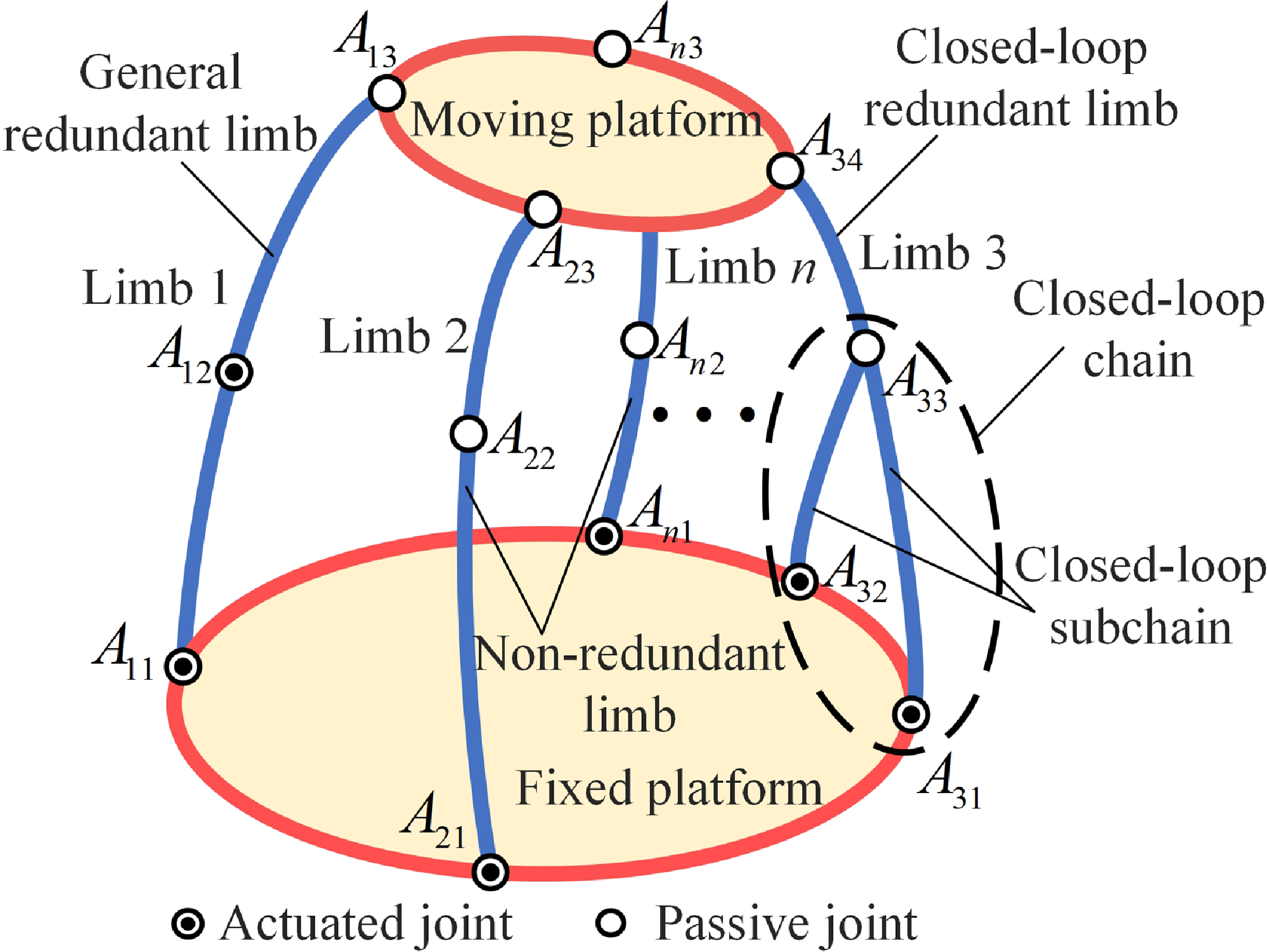
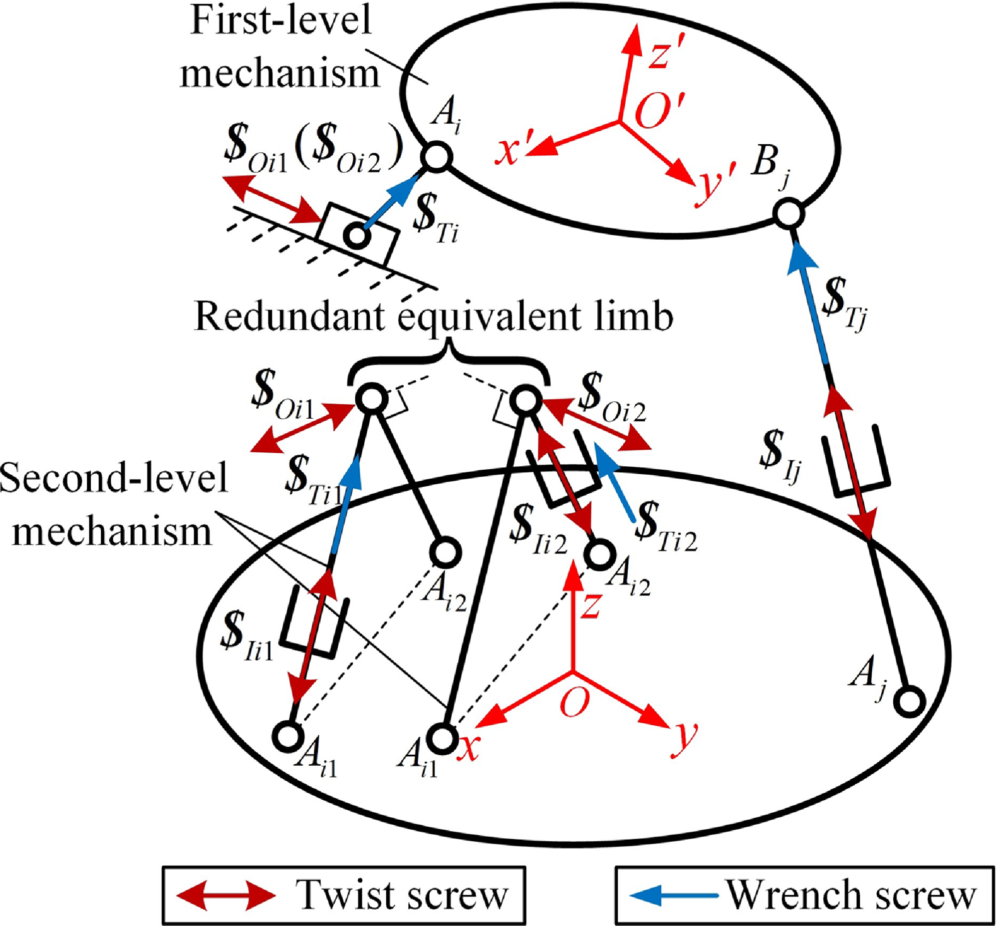
Based on the distribution of actuated joints, kinematically redundant PMs can be classified into two types: those with general redundant limbs and those with closed-loop redundant limbs. This classification is illustrated in Fig. 1. In general redundant limbs, multiple actuated joints are connected in series. By contrast, closed-loop redundant limbs, characterized by internal closed-chain structures, feature multiple actuated joints arranged in parallel.
Topological structure of the kinematically redundant parallel mechanism.

Kinematic redundancy reduces the rank of the twist screw system of a limb, making it lower than the number of twist screws. This implies that the twist screws are not linearly independent. Since the twist screws of some actuated joints can be expressed as linear combinations of others, calculating the corresponding transmission wrench screw solely by locking a specific actuated joint is not applicable.
Assume that the limb contains
 $n$
actuated joints and
 $m$
passive joints. The corresponding twist screw system can be expressed as
 \begin{equation} \boldsymbol{U}=\left\{{\boldsymbol{\$}}_{I1},{\boldsymbol{\$}}_{I2},\cdot \cdot \cdot,{\boldsymbol{\$}}_{In};{\boldsymbol{\$}}_{1},{\boldsymbol{\$}}_{2},\cdot \cdot \cdot,{\boldsymbol{\$}}_{m}\right\} \end{equation}
where
 ${\boldsymbol{\$}}_{In}$
and
 ${\boldsymbol{\$}}_{m}$
represent the actuated and passive joint screws, respectively.
When the
 $i\text{-}{\textrm{th}}$
actuated joint is in motion, the remaining (
 $n-1$
) actuated joints are treated as fixed. In other words, the motion of these joints does not affect the motion characteristic of the
 $i\text{-}{\textrm{th}}$
actuated joint. Under this condition, the redundant limb degenerates into a nonredundant limb with a single actuated joint. The remaining actuated joints should therefore be excluded from the limb’s twist screw system. Accordingly, the twist screw system of the limb is expressed as
 \begin{equation} \boldsymbol{U}_{i}=\left\{{\boldsymbol{\$}}_{Ii};{\boldsymbol{\$}}_{1},{\boldsymbol{\$}}_{2},\cdot \cdot \cdot,{\boldsymbol{\$}}_{m}\right\} \end{equation}
When the
 $i\text{-}{\textrm{th}}$
actuated joint is locked, the resulting screw system is given by
 \begin{equation} \overline{\boldsymbol{U}}_{i}=\left\{{\boldsymbol{\$}}_{1},{\boldsymbol{\$}}_{2},\cdot \cdot \cdot,{\boldsymbol{\$}}_{m}\right\} \end{equation}
Reciprocal calculations are performed on
 $\boldsymbol{U}_{i}$
and
 $\overline{\boldsymbol{U}}_{i}$
to derive the corresponding constraint screw systems
 $\boldsymbol{U}_{Ci}$
and
 $\overline{\boldsymbol{U}}_{Ci}$
. Compared to
 $\boldsymbol{U}_{Ci}, \overline{\boldsymbol{U}}_{Ci}$
contains one additional constraint screw, which corresponds to the transmission wrench screw
 ${\boldsymbol{\$}}_{Ti}$
of the
 $i\text{-}{\textrm{th}}$
actuated joint. By applying the same procedure to the remaining (
 $n-1$
) actuated joints, the redundant limb can be decomposed into n nonredundant limbs, allowing the calculation of the transmission wrench screw
 ${\boldsymbol{\$}}_{Ti}$
for each actuated joint. This approach of decomposing a redundant limb into multiple nonredundant limbs is referred to as “redundancy decomposition”.
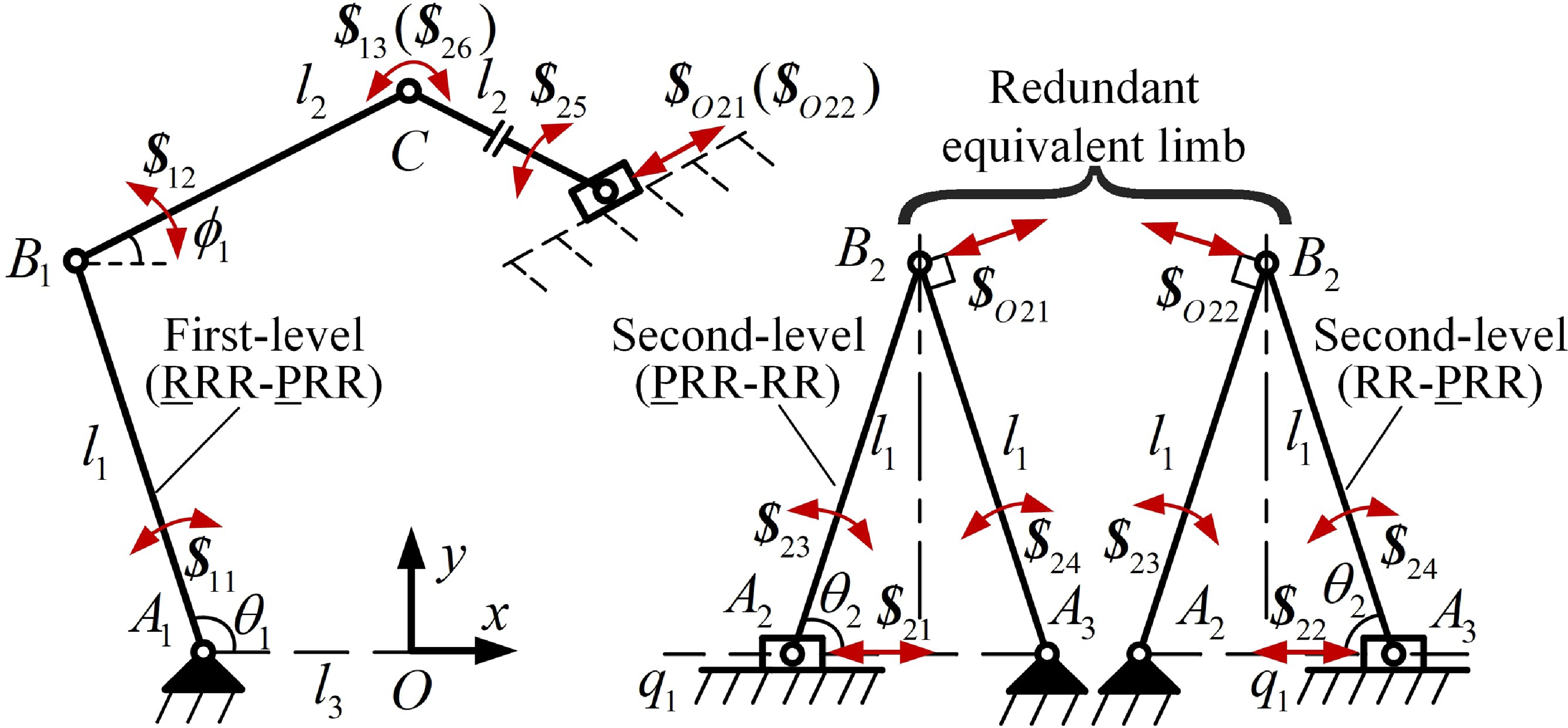
However, in a redundant limb incorporating a closed-loop chain, the closed-loop structure persists even after applying redundancy decomposition. The twist screws of joints within and outside the loop are linearly dependent. Therefore, a hierarchical operation must be applied to such limbs. In this process, the closed-loop system is treated as an independent second-level mechanism, upon which redundancy decomposition is subsequently performed. Excluding the closed-loop, the remaining part of the redundant limb, along with the nonredundant limbs, forms the first-level mechanism. The output motion of the second-level mechanism serves as the input to the first-level mechanism, thereby enabling the computation of the transmission wrench screw
 ${\boldsymbol{\$}}_{Ti}$
for each actuated joint. This procedure is referred to as “hierarchical division”.
2.2.2. Definition of the LTI
Each actuated joint in a kinematically redundant PM operates independently and can generate its own transmission force and output motion. Accordingly, each actuated joint possesses distinct input and output transmission efficiencies. By applying the aforementioned methods of redundancy decomposition and hierarchical division, the mechanism can be decomposed into multiple nonredundant subsystems. The transmission wrench screw
 ${\boldsymbol{\$}}_{Tij}$
and the output twist screw
 ${\boldsymbol{\$}}_{Oij}$
corresponding to the
 $j\text{-}{\textrm{th}}$
actuated joint in the
 $i\text{-}{\textrm{th}}$
limb can thus be derived.
Procedures of motion/force transmission performance evaluation.

Therefore, the power coefficient of
 ${\boldsymbol{\$}}_{Tij}$
with respect to
 ${\boldsymbol{\$}}_{Iij}$
and
 ${\boldsymbol{\$}}_{Oij}$
can be expressed as
 \begin{equation} \lambda _{ij}\boldsymbol{=}\frac{\left| {\boldsymbol{\$}}_{Tij}\circ {\boldsymbol{\$}}_{Iij}\right| }{\left| {\boldsymbol{\$}}_{Tij}\circ {\boldsymbol{\$}}_{Iij}\right| _{\max }}; \quad \eta _{ij}\boldsymbol{=}\frac{\left| {\boldsymbol{\$}}_{Tij}\circ {\boldsymbol{\$}}_{Oij}\right| }{\left| {\boldsymbol{\$}}_{Tij}\circ {\boldsymbol{\$}}_{Oij}\right| _{\max }} \end{equation}
To evaluate the input and output performance of the mechanism, the minimum values of the input and output power coefficients are defined as the ITI and the OTI, respectively. These indices are mathematically defined as
 \begin{align} \lambda _{I} &=\min \left\{\lambda _{11},\lambda _{12}\cdots \lambda _{ij}\right\}; \end{align}
 \begin{align} \eta _{O} &=\min \left\{\eta _{11},\eta _{12}\cdots \eta _{ij}\right\} \end{align}
The LTI is then defined as the minimum of the ITI and OTI.
 \begin{equation} \gamma =\min \left\{\lambda _{I},\eta _{O}\right\} \end{equation}
The ITI
 $\lambda _{I}$
, OTI
 $\eta _{O}$
, and LTI
 $\gamma$
are all dimensionless quantities and are invariant under coordinate transformations. Their values range from 0 to 1, with higher values indicating better transmission performance.
2.2.3. Procedure for evaluating motion/Force transmission performance of kinematically redundant parallel mechanisms
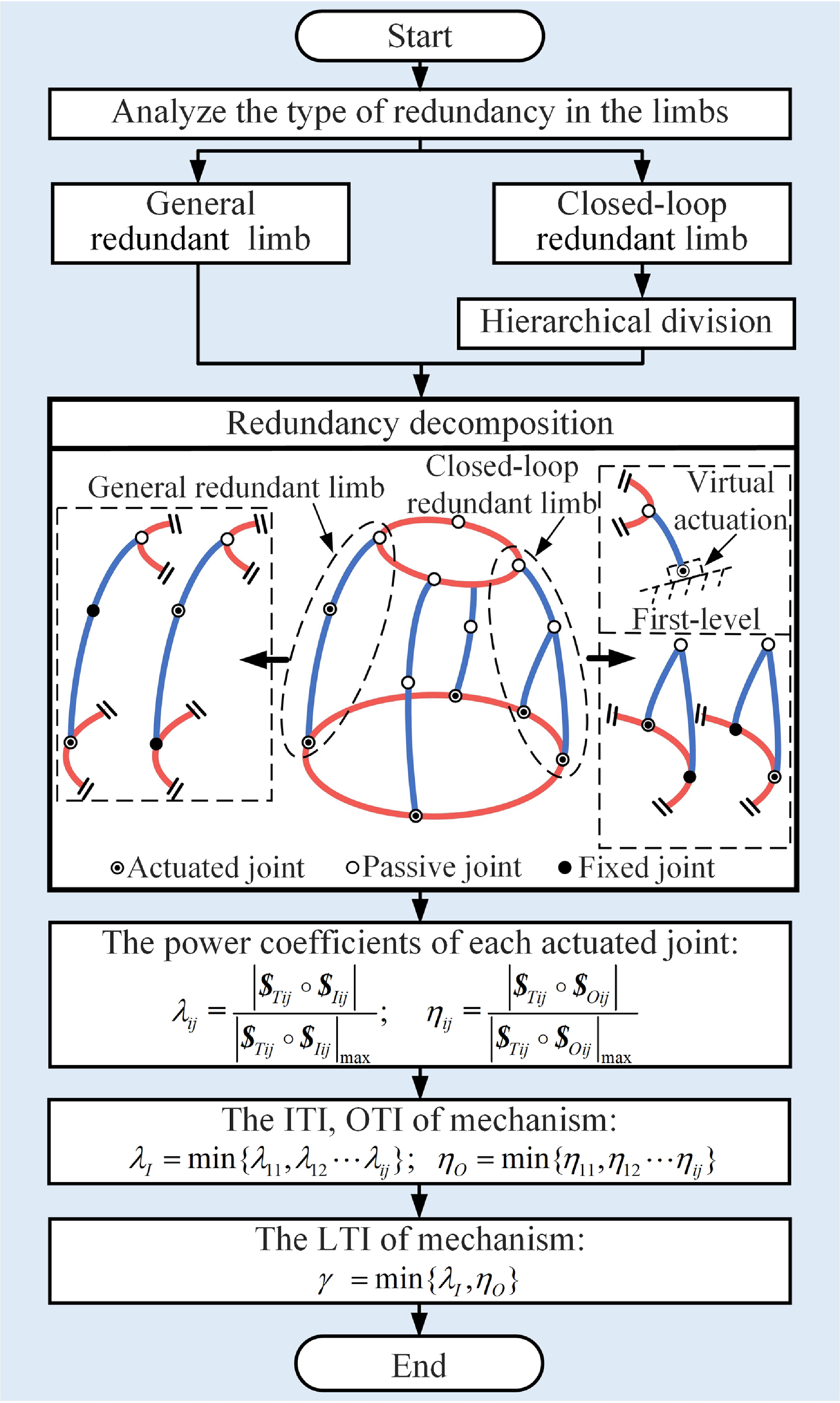
The procedures for evaluating the motion/force transmission performance of kinematically redundant PMs are shown in Fig. 2. The detailed steps are outlined as follows:
-
i. The topological structure of the kinematically redundant PM is analyzed to determine its type of redundancy. Redundancy decomposition is directly applied to general redundant limbs, whereas hierarchical division is performed first for closed-loop redundant limbs. This process results in several equivalent nonredundant PMs.
-
ii. Calculate the transmission wrench screw
 ${\boldsymbol{\$}}_{Tij}$
and output twist screw
${\boldsymbol{\$}}_{Oij}$
for each equivalent nonredundant PM, then determine the input power coefficients
$\lambda _{ij}$
and output power coefficients
$\eta _{ij}$
for each actuated joint.
-
iii. The ITI, OTI, and LTI for the kinematically redundant PM can be obtained. By computing the LTI values across the workspace, the motion/force transmission performance of the kinematically redundant parallel mechanism is effectively evaluated.


2.3. LTI for kinematically redundant PMs with general redundant limbs
Using the
 $\underline{\textrm{R}}{\textrm{RR}}-\underline{\textrm{P}}\underline{\textrm{R}}{\textrm{RR}}$
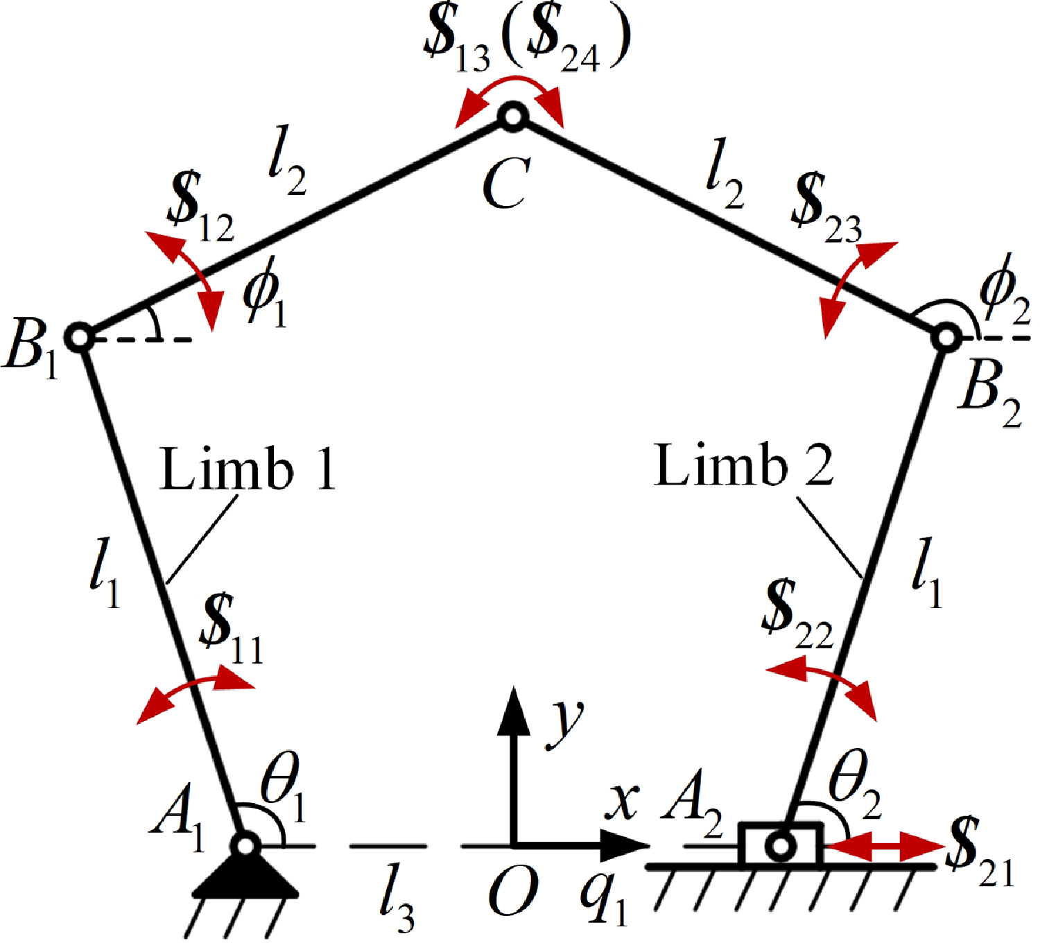
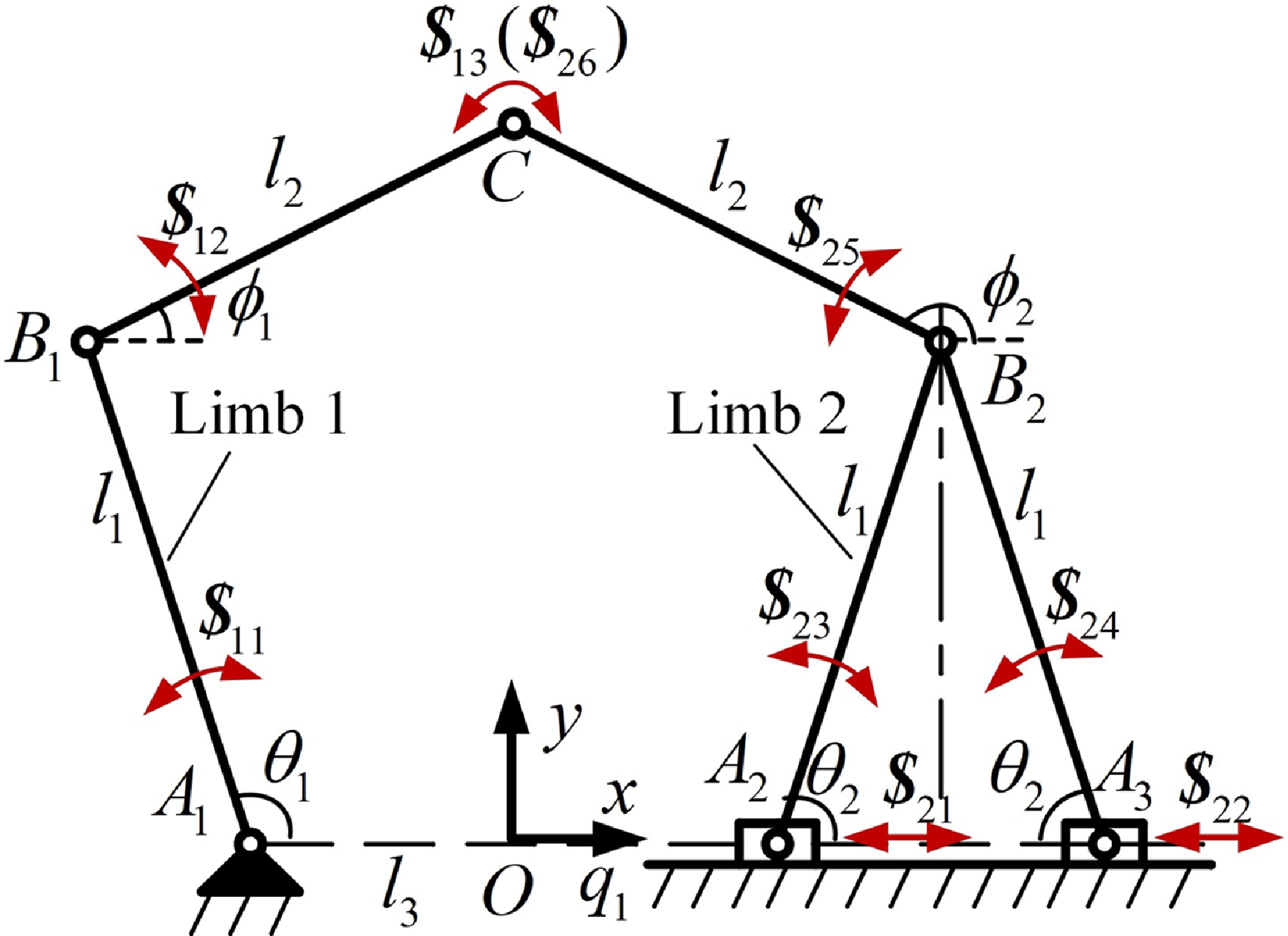
planar kinematically redundant PM as an example (P: prismatic joint, R: revolute joint, with underlined symbols representing actuated joints), the method for calculating the LTI of kinematically redundant PMs with general redundant limbs is explained. As shown in Fig. 3, it consists of a moving platform, a fixed base, limb 1, and limb 2. Limb 1 is nonredundant, while limb 2 is generally redundant limb, with the actuated P and R joints arranged in series. The axis of the revolute joint point
 $C$
is actually the moving platform, which maintains a fixed orientation. The moving platform has two translational DOFs along the
 $x$
and
 $y$
axes. In Fig. 3,
 $\theta _{1}, \theta _{2}$
, and
 $q_{1}$
represent the input parameters of the actuated joints;
 $l_{1}$
and
 $l_{2}$
denote the lengths of links
 $A_{1}B_{1}, A_{2}B_{2}$
and
 $B_{1}C , B_{2}C$
, respectively; and
 $l_{3}$
represents the horizontal distance between point
 $A_{1}$
and the origin along the
 $x$
axis.
The
 $\underline{R}RR-\underline{P}\underline{R}RR$
mechanism.

2.3.1. Input transmission index
For the twist screw system of limb 1, it is denoted as
 $\boldsymbol{U}_{1}=\{{\boldsymbol{\$}}_{11},{\boldsymbol{\$}}_{12},{\boldsymbol{\$}}_{13}\}$
, where
 ${\boldsymbol{\$}}_{11}$
represents the input twist screw corresponding to the actuated R joint. The three twist screws are expressed as follows:
 \begin{eqnarray} \left\{\begin{array}{l} {\boldsymbol{\$}}_{11}=\left(0,0,1; \; 0,l_{3},0\right)\\[2pt] {\boldsymbol{\$}}_{12}=\left(0,0,1; \; l_{1}{\textrm{s}}\theta _{1},l_{3}-l_{1}{\textrm{c}}\theta _{1},0\right)\\[2pt] {\boldsymbol{\$}}_{13}=\left(0,0,1; \; l_{2}{\textrm{s}}\phi _{1}+l_{1}{\textrm{s}}\theta _{1},l_{3}-l_{2}{\textrm{c}}\phi _{1}-l_{1}\theta _{1},0\right) \end{array}\right. \end{eqnarray}
where
 ${\boldsymbol{\$}}_{ij}$
represents the twist screw of the
 $j\text{-}{\textrm{th}}$
joint in the
 $i\text{-}{\textrm{th}}$
limb.
 $s$
and
 $c$
are abbreviations for the trigonometric functions sin and cos, respectively.
The rank of twist screw system
 $\boldsymbol{U}_{1}$
is
 $d_{1}=\dim (\boldsymbol{U}_{1})=3$
, and the number of twist screws is
 $c_{1}=\text{card}(\boldsymbol{U}_{1})=3$
. Since
 $d_{1}=c_{1}$
, all the twist screws in the system are independent.
The reciprocal operation on the limb’s twist screw system
 $\boldsymbol{U}_{1}$
yields the constraint screw system
 $\boldsymbol{U}_{C1}=\{{\boldsymbol{\$}}_{C11},{\boldsymbol{\$}}_{C12},{\boldsymbol{\$}}_{C13}\}$
, which is expressed as follows:
 \begin{eqnarray} \left\{\begin{array}{l} {\boldsymbol{\$}}_{C11}=\left(0,0,1;\, 0,0,0\right)\\[2pt] {\boldsymbol{\$}}_{C12}=\left(0,0,0;\, 1,0,0\right)\\[2pt] {\boldsymbol{\$}}_{C13}=\left(0,0,0;\, 0,1,0\right) \end{array}\right. \end{eqnarray}
where
 ${\boldsymbol{\$}}_{Cij}$
denotes the
 $j\text{-}{\textrm{th}}$
constraint screw of the
 $i\text{-}{\textrm{th}}$
limb.
Lock the actuated R joint in limb 1, and remove the associated twist screw
 ${\boldsymbol{\$}}_{11}$
from
 $\boldsymbol{U}_{1}$
. This results in a new screw system, denoted as
 ${\overline{\boldsymbol{U}}_{1}=\{{\boldsymbol{\$}}_{12},{\boldsymbol{\$}}_{13}\}}$
. By calculating the reciprocal screw of
 $\overline{\boldsymbol{U}}_{1}$
, a constraint screw system
 $\overline{\boldsymbol{U}}_{C1}$
can be obtained. The additional screw in
 $\overline{\boldsymbol{U}}_{C1}$
that is not present in
 $\boldsymbol{U}_{C1}$
corresponds to the transmission wrench screw of limb 1, and it is denoted as
 \begin{equation} {\boldsymbol{\$}}_{T1}=\left({\textrm{c}}\phi _{1},{\textrm{s}}\phi _{1},0; \; 0,0,-\!\left(l_{3}{\textrm{s}}\phi _{1}+l_{1}{\textrm{s}}\left(\theta _{1}-\phi _{1}\right)\right)\right) \end{equation}
where
 ${\boldsymbol{\$}}_{T1}$
denotes a pure force along the direction of
 $B_{1}C$
and passing through point
 $C$
.
Similarly, the twist screw system of limb 2 is denoted as
 $\boldsymbol{U}_{2}=\{{\boldsymbol{\$}}_{21},{\boldsymbol{\$}}_{22},{\boldsymbol{\$}}_{23},{\boldsymbol{\$}}_{24}\}$
, in which
 ${\boldsymbol{\$}}_{21}$
and
 ${\boldsymbol{\$}}_{22}$
are the input twist screws corresponding to the actuated R and P joints, respectively. The expressions for these twist screws are given as follows:
 \begin{eqnarray} \left\{\begin{array}{l} {\boldsymbol{\$}}_{21}=\left(0,0,0; \; 1,0,0\right)\\ {\boldsymbol{\$}}_{22}=\left(0,0,1; \; 0,-q_{1},0\right)\\ {\boldsymbol{\$}}_{23}=\left(0,0,1; \; l_{1}{\textrm{s}}\theta _{2},-\!\left(q_{1}+l_{1}{\textrm{c}}\theta _{2}\right),\, 0\right)\\ {\boldsymbol{\$}}_{24}=\left(0,0,1; \; l_{2}{\textrm{s}}\phi _{2}+l_{1}{\textrm{s}}\theta _{2},-\!\left(q_{1}+l_{2}{\textrm{c}}\phi _{2}+l_{1}{\textrm{c}}\theta _{2}\right),0\right) \end{array}\right. \end{eqnarray}
The rank of the twist screw system
 $\boldsymbol{U}_{2}$
is
 $d_{2}=\dim (\boldsymbol{U}_{2})=3$
, and the number of twist screws is
 $c_{2}=\text{card}(\boldsymbol{U}_{2})=4$
. Since
 $d_{2}\lt c_{2}$
, the twist screws in the system are not fully independent.
The constraint screw system of limb 2 can be derived and is denoted as
 $\boldsymbol{U}_{C2}=\{{\boldsymbol{\$}}_{C21},{\boldsymbol{\$}}_{C22},{\boldsymbol{\$}}_{C23}\}$
. By locking the actuated P joint and removing the corresponding twist screw
 ${\boldsymbol{\$}}_{21}$
from
 $\boldsymbol{U}_{2}$
, a new screw system
 $\overline{\boldsymbol{U}}_{21}=\{{\boldsymbol{\$}}_{22},{\boldsymbol{\$}}_{23},{\boldsymbol{\$}}_{24}\}$
, is obtained. The reciprocal screw system of
 $\overline{\boldsymbol{U}}_{21}$
is denoted as
 $\overline{\boldsymbol{U}}_{C21}$
, which turns out to be the same as
 $\boldsymbol{U}_{C2}$
. As a result, no new force screw is generated. Similarly, when the actuated R joint is locked, the resulting constraint screw system
 $\overline{\boldsymbol{U}}_{C22}$
is the same as
 $\boldsymbol{U}_{C2}$
.Therefore, it is not possible to determine the transmission wrench screws corresponding to the actuated P and R joints merely by locking the joints individually.
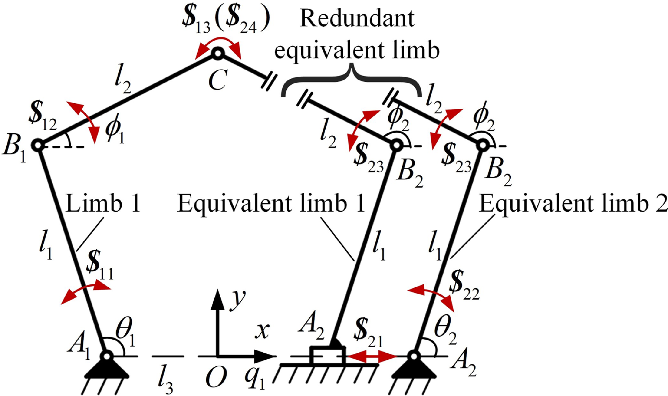
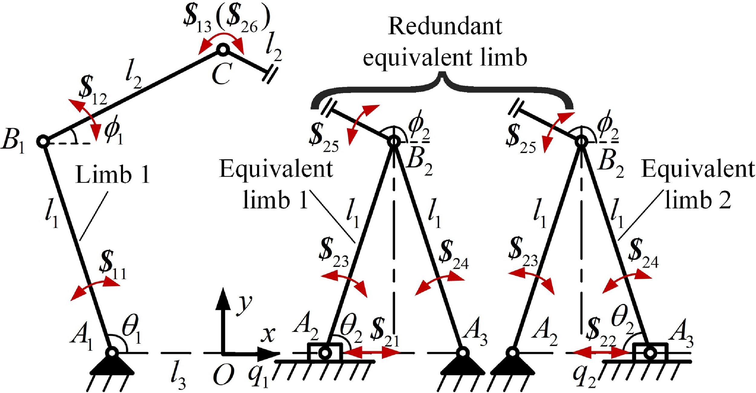
To address this, the “redundancy decomposition” method introduced in Section 2.2 is adopted. The actuated P and R joints in limb 2 are treated as fixed one at a time, resulting in two single-actuated limbs
 $\underline{\textrm{R}}{\textrm{RR}}$
and
 $\underline{\textrm{P}}{\textrm{RR}}$
, which are referred to as equivalent limbs 1 and 2, as shown in Fig. 4.
Redundancy decomposition of the
 $\underline{R}RR-\underline{P}\underline{R}RR$
mechanism.

In equivalent limb 1, P joint is actuated while R joint is fixed. The twist screw system of the limb, denoted as
 $\boldsymbol{U}_{21}=\{{\boldsymbol{\$}}_{21},{\boldsymbol{\$}}_{23},{\boldsymbol{\$}}_{24}\}$
, contains the same twist screws
 ${\boldsymbol{\$}}_{21},{\boldsymbol{\$}}_{23},{\boldsymbol{\$}}_{24}$
as those given in Eq.(15). Its corresponding constraint screw system, denoted as
 $\boldsymbol{U}_{C21}=\boldsymbol{U}_{C2}$
, is identical to that in Eq. (13). When the actuated P joint is locked, a new twist screw system, denoted as
 $\overline{\boldsymbol{U}}_{21}=\{{\boldsymbol{\$}}_{23},{\boldsymbol{\$}}_{24}\}$
, is obtained. Its corresponding constraint screw system
 $\overline{\boldsymbol{U}}_{C21}$
contains one additional constraint wrench screw compared to
 $\boldsymbol{U}_{C21}$
. This additional constraint wrench screw is identified as the transmission wrench screw
 ${\boldsymbol{\$}}_{T21}$
corresponding to the actuated P joint and is expressed as
 \begin{equation} {\boldsymbol{\$}}_{T21}=\left({\textrm{c}}\phi _{2},{\textrm{s}}\phi _{2},0; \; 0,0,\left(q_{1}{\textrm{s}}\phi _{2}-l_{1}{\textrm{s}}\left(\theta _{2}-\phi _{2}\right)\right)\right) \end{equation}
A similar procedure is applied to equivalent limb 2, where R joint is actuated and P joint is fixed. The corresponding transmission wrench screw for the actuated R joint, denoted as
 ${\boldsymbol{\$}}_{T22}$
, can be obtained as follows:
 \begin{equation} {\boldsymbol{\$}}_{T22}=\left({\textrm{c}}\phi _{2},{\textrm{s}}\phi _{2},0; \; 0,0,\left(q_{1}{\textrm{s}}\phi _{2}-l_{1}{\textrm{s}}\left(\theta _{2}-\phi _{2}\right)\right)\right) \end{equation}
where
 ${\boldsymbol{\$}}_{T21}$
and
 ${\boldsymbol{\$}}_{T22}$
are identical, both representing a pure force directed along link
 $B_{2}C$
and passing through point
 $C$
. Since link
 $B_{2}C$
is a two-force member, the transmission force must act along its axis.
By applying the redundancy decomposition method, the transmission wrench screws corresponding to the actuated joints are determined. Based on Eq. (8), the input power coefficients for each actuated joint can then be expressed as
 \begin{equation} \lambda _{1}=\frac{\left| {\boldsymbol{\$}}_{11}\circ {\boldsymbol{\$}}_{T1}\right| }{\left| {\boldsymbol{\$}}_{11}\circ {\boldsymbol{\$}}_{T1}\right| _{\max }}; \quad \lambda _{21}=\frac{\left| {\boldsymbol{\$}}_{21}\circ {\boldsymbol{\$}}_{T21}\right| }{\left| {\boldsymbol{\$}}_{21}\circ {\boldsymbol{\$}}_{T21}\right| _{\max }}; \quad \lambda _{22}=\frac{\left| {\boldsymbol{\$}}_{22}\circ {\boldsymbol{\$}}_{T22}\right| }{\left| {\boldsymbol{\$}}_{22}\circ {\boldsymbol{\$}}_{T22}\right| _{\max }} \end{equation}
According to Eq. (9), the ITI is given by
 \begin{equation} \lambda _{I}=\min \left\{\lambda _{1},\lambda _{21},\lambda _{22}\right\}; \end{equation}
2.3.2. Output transmission index
The common constraint screw of the mechanism is
 $\boldsymbol{U}_{C}=\boldsymbol{U}_{C1}\cap \boldsymbol{U}_{C2}$
. The constraint couple restricting the rotation of the moving platform is
 ${\boldsymbol{\$}}=(0,0,0;\;0,0,1)$
. Therefore, the common constraint screw system is denoted as
 $\boldsymbol{U}_{C}=\{{\boldsymbol{\$}}_{C1},\,{\boldsymbol{\$}}_{C2},\,{\boldsymbol{\$}}_{C3},\,{\boldsymbol{\$}}_{C4}\}$
, and expressed as follows:
 \begin{eqnarray} \left\{\begin{array}{l} {\boldsymbol{\$}}_{C1}=\left(0,0,1;\,0,0,0\right)\\ {\boldsymbol{\$}}_{C2}=\left(0,0,0;\,1,0,0\right)\\ {\boldsymbol{\$}}_{C3}=\left(0,0,0;\,0,1,0\right)\\ {\boldsymbol{\$}}_{C4}=\left(0,0,0;\,0,0,1\right) \end{array}\right. \end{eqnarray}
To calculate the output twist screw
 ${\boldsymbol{\$}}_{Oi}$
corresponding to the
 $i\text{-}{\textrm{th}}$
actuated joint, that actuated joint is retained while all other actuated joints are locked. Under this condition, the moving platform is constrained by a fifth-order constraint screw system, leaving it with a single degree of freedom that corresponds to the output twist screw
 ${\boldsymbol{\$}}_{Oi}$
. By sequentially locking all actuated joints except the
 $i\text{-}{\textrm{th}}$
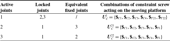
one, the combinations of constraint screws acting on the moving platform are obtained, as listed in Table I.
The combination of constraint screws acting on the moving platform.

Note: The numbers 1 denotes the actuated R joint in limb 1, while 2 and 3 denote the actuated P and R joints in limb 2.
Note that, when calculating the output twist screw corresponding to actuated P (or R) joint, all actuated joints on the other limbs must be locked. The remaining actuated R (or P) joint on the same limb is considered equivalent fixed and should therefore remain unlocked. By computing the reciprocal screws of the constraint screw combinations
 $\boldsymbol{U}_{C}^{1},\boldsymbol{U}_{C}^{21}\text{ and }\boldsymbol{U}_{C}^{22}$
acting on the moving platform, the output twist screws i-th corresponding to each actuated joint can be derived as follows:
 \begin{align} {\boldsymbol{\$}}_{O1} &=\left(0,0,0;-{\textrm{s}}\phi _{2},{\textrm{c}}\phi _{2},0\right) \end{align}
 \begin{align} {\boldsymbol{\$}}_{O21} &={\boldsymbol{\$}}_{O22}=\left(0,0,0;-{\textrm{s}}\phi _{1},{\textrm{c}}\phi _{1},0\right) \end{align}
The output twist screws
 ${\boldsymbol{\$}}_{O21}$
and
 ${\boldsymbol{\$}}_{O22}$
are equal, which is consistent with the conclusion that
 ${\boldsymbol{\$}}_{T21}$
and
 ${\boldsymbol{\$}}_{T22}$
are equal. Based on Eq. (8), the output power coefficients corresponding to actuated joints are
 \begin{equation} \eta _{1}=\frac{\left| {\boldsymbol{\$}}_{O1}\circ {\boldsymbol{\$}}_{T1}\right| }{\left| {\boldsymbol{\$}}_{O1}\circ {\boldsymbol{\$}}_{T1}\right| _{\max }}; \quad \eta _{21}=\frac{\left| {\boldsymbol{\$}}_{O21}\circ {\boldsymbol{\$}}_{T21}\right| }{\left| {\boldsymbol{\$}}_{O21}\circ {\boldsymbol{\$}}_{T21}\right| _{\max }}; \quad \eta _{22}=\frac{\left| {\boldsymbol{\$}}_{O22}\circ {\boldsymbol{\$}}_{T22}\right| }{\left| {\boldsymbol{\$}}_{O22}\circ {\boldsymbol{\$}}_{T22}\right| _{\max }} \end{equation}
The OTI of the mechanism is defined according to Eq. (10) as
 \begin{equation} \eta _{O}=\min \left\{\eta _{1},\eta _{21},\eta _{22}\right\} \end{equation}
Thus, the LTI of the
 $\underline{\textrm{R}}{\textrm{RR}}-\underline{\textrm{P}}\underline{\textrm{R}}{\textrm{RR}}$
mechanism given by
 \begin{equation} \gamma =\min \left\{\lambda _{I},\eta _{O}\right\} \end{equation}
The dimensional parameters of the given
 $\underline{\textrm{R}}{\textrm{RR}}-\underline{\textrm{P}}\underline{\textrm{R}}{\textrm{RR}}$
mechanism are as follows:
 $l_{1}=110\text{ mm}$
,
 $l_{2}=100\text{ mm},l_{3}=55\text{ mm}$
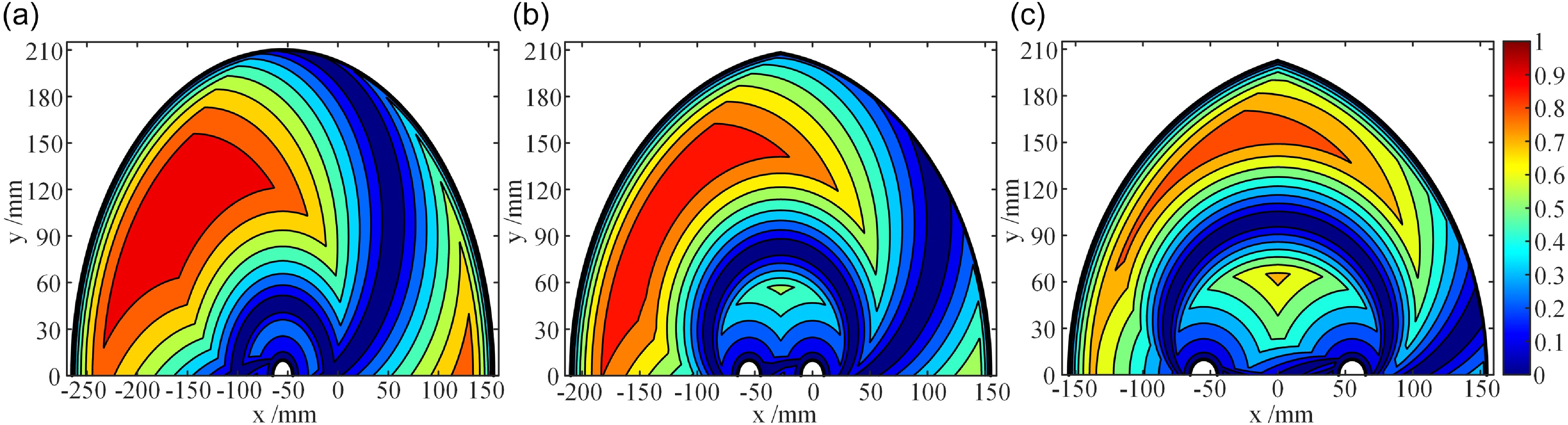
. When the input value
 $q_{1}$
of the actuated P joint in limb 2 is set to − 55, 0, 55 mm, respectively, the corresponding LTI distributions across the mechanism’s workspace are illustrated in Fig. 5. According to ref. [Reference Liu, Wu and Wang38], an input transmission singularity occurs when the motion of at least one actuated joint at the input side cannot be transmitted by the wrench screw (i.e., ITI = 0). An output transmission singularity occurs when the output motion of any degree of freedom of the moving platform cannot be achieved by the wrench screw (i.e., OTI = 0). In each figure, the bold black boundary line represents the singularity boundary of the mechanism, where input transmission singularities occur. The dark blue striped region indicates the internal singular trajectory zone, where output transmission singularities occur. The overlapping region corresponds to mixed singularities, where both input and output transmission singularities occur simultaneously.
LTI distribution of
 $\underline{R}RR-\underline{P}\underline{R}RR$
mechanism: (a)
 $q_{1}=-\mathit{55}\, \text{mm}$
; (b)
 $q_{1}=\mathit{0}\, \text{mm}$
; (c)
 $q_{1}=\mathit{55}\, \text{mm}$
.

2.4. LTI for kinematically redundant PMs with closed-loop redundant limbs
When the actuated joints of the general redundant limb 2 in the aforementioned
 $\underline{\textrm{R}}{\textrm{RR}}-\underline{\textrm{P}}\underline{\textrm{R}}{\textrm{RR}}$
mechanism are arranged in a parallel configuration, the two subchains form a closed-loop chain, denoted as
 $[\underline{\textrm{P}}{\textrm{R}}-\underline{\textrm{P}}{\textrm{R}}]{\textrm{R}}$
. This configuration results in a kinematically redundant PM
 $\underline{\textrm{R}}{\textrm{RR}}-[\underline{\textrm{P}}{\textrm{R}}-\underline{\textrm{P}}{\textrm{R}}]{\textrm{RR}}$
with a closed-loop redundant limb, as shown in Fig. 6. The closed-loop chain
 $[\underline{\textrm{P}}{\textrm{R}}-\underline{\textrm{P}}{\textrm{R}}]{\textrm{R}}$
is formed by two subchains
 $\underline{\textrm{P}}{\textrm{RR}}$
converging at a composite hinge point
 $B_{2}$
. The orientation of the hinge point
 $B_{2}$
in the closed-loop chain is fixed, thus it has two DOF, allowing translational motion along the
 $x$
and
 $y$
axes. The symbols used for the dimensional parameters in Fig. 6 are consistent with those in Fig. 3.
The RRR-[PR-PR]RR PM.

Redundancy decomposition of the RRR-[PR-PR]RR PM.

2.4.1. Input transmission index
The redundancy decomposition of the closed-loop redundant limb
 $[\underline{\textrm{P}}{\textrm{R}}-\underline{\textrm{P}}{\textrm{R}}]{\textrm{RR}}$
of the mechanism results in two equivalent nonredundant limbs,
 $[\underline{\textrm{P}}{\textrm{R}}-{\textrm{PR}}]{\textrm{RR}}$
and
 $[{\textrm{PR}}-\underline{\textrm{P}}{\textrm{R}}]{\textrm{RR}}$
, which are referred to as equivalent limb 1 and equivalent limb 2, respectively, as shown in Fig. 7. The twist screw systems of the two equivalent limbs are denoted by
 $\boldsymbol{U}_{21}=\{{\boldsymbol{\$}}_{21},{\boldsymbol{\$}}_{23},{\boldsymbol{\$}}_{24},{\boldsymbol{\$}}_{25},{\boldsymbol{\$}}_{26}\}$
and
 $\boldsymbol{U}_{22}=\{{\boldsymbol{\$}}_{22},{\boldsymbol{\$}}_{23},{\boldsymbol{\$}}_{24},{\boldsymbol{\$}}_{25},{\boldsymbol{\$}}_{26}\}$
, where
 ${\boldsymbol{\$}}_{21}$
and
 ${\boldsymbol{\$}}_{22}$
are the input twist screws. Each screw is expressed as
 \begin{eqnarray} \left\{\begin{array}{l} {\boldsymbol{\$}}_{21}=\left(0,0,0; \; 1,0,0\right)\\ {\boldsymbol{\$}}_{22}=\left(0,0,0; \; 1,0,0\right)\\ {\boldsymbol{\$}}_{23}=\left(0,0,1; \; 0,-q_{1},0\right)\\ {\boldsymbol{\$}}_{24}=\left(0,0,1; \; 0,-q_{2},0\right)\\ {\boldsymbol{\$}}_{25}=\left(0,0,1; \; l_{1}{\textrm{s}}\theta _{2},-\!\left(q_{1}+l_{1}\theta _{2}\right),0\right)\\ {\boldsymbol{\$}}_{26}=\left(0,0,1; \; l_{2}{\textrm{s}}\phi _{2}+l_{1}{\textrm{s}}\theta _{2},-\!\left(q_{1}+l_{2}{\textrm{c}}\phi _{2}+l_{1}{\textrm{c}}\theta _{2}\right),0\right) \end{array}\right. \end{eqnarray}
The ranks of the screw systems
 $\boldsymbol{U}_{21}$
and
 $\boldsymbol{U}_{22}$
are
 $d_{21(22)}=\dim (\boldsymbol{U}_{21(22)})=3$
, while the numbers of screws in the systems are
 $c_{21(22)}=5$
. Since
 $d_{21(22)}\lt c_{21(22)}$
, the twist screw systems of equivalent limbs 1 and 2 are still linearly dependent.
Therefore, the method of “hierarchical division” described in Section 2.2 is applied to the
 $\underline{\textrm{R}}{\textrm{RR}}-[\underline{\textrm{P}}{\textrm{R}}-\underline{\textrm{P}}{\textrm{R}}]{\textrm{RR}}$
mechanism. The closed-loop chain
 $[\underline{\textrm{P}}{\textrm{R}}-\underline{\textrm{P}}{\textrm{R}}]{\textrm{R}}$
in the redundant limb is regarded as an independent second-level mechanism, while the nonredundant limb and the remaining part of the redundant limb are considered as a first-level mechanism. The output motion of the second-level mechanism acts as the input motion for the first-level mechanism. Ultimately, through hierarchical division and redundancy decomposition, the
 $\underline{\textrm{R}}{\textrm{RR}}-[\underline{\textrm{P}}{\textrm{R}}-\underline{\textrm{P}}{\textrm{R}}]{\textrm{RR}}$
mechanism is decomposed into a nonredundant first-level mechanism
 $\underline{\textrm{R}}{\textrm{RR}}-\underline{\textrm{P}}{\textrm{RR}}$
and two second-level mechanisms
 $\underline{\textrm{P}}\text{RR-RR}$
and
 ${\textrm{RR}}-\underline{\textrm{P}}{\textrm{RR}}$
, as shown in Fig. 8.
Redundancy decomposition and hierarchical division of the RRR-[PR-PR]RR PM.

The second-level mechanism
 $\underline{\textrm{P}}\text{RR-RR}$
is a single DOF system actuated by P joint. The twist screw system of its
 $\underline{\textrm{P}}{\textrm{RR}}$
limb is denoted by
 $\boldsymbol{U}_{21}=\{{\boldsymbol{\$}}_{21},{\boldsymbol{\$}}_{23},{\boldsymbol{\$}}_{25}\}$
.The transmission wrench screw corresponding to actuated P joint is computed as
 \begin{equation} {\boldsymbol{\$}}_{T21}=\left({\textrm{c}}\theta _{2},{\textrm{s}}\theta _{2},0; \; 0,0,q_{1}{\textrm{s}}\theta _{2}\right) \end{equation}
where
 ${\boldsymbol{\$}}_{T21}$
represents a pure force acting along the direction of
 $A_{2}B_{2}$
and passing through point
 $B_{2}$
, causing the hinge point
 $B_{2}$
to undergo instantaneous translational motion perpendicular to this direction. Therefore, the output twist screw corresponding to this motion are expressed as
 \begin{equation} {\boldsymbol{\$}}_{O21}=\left(0,0,0; \; {\textrm{s}}\theta _{2},{\textrm{c}}\theta _{2},0\right) \end{equation}
According to Eq. (8), the input and output power coefficients of the second-level mechanism
 $\underline{\textrm{P}}\text{RR-RR}$
are given by
 \begin{equation} \lambda _{21}=\frac{\left| {\boldsymbol{\$}}_{21}\circ {\boldsymbol{\$}}_{T21}\right| }{\left| {\boldsymbol{\$}}_{21}\circ {\boldsymbol{\$}}_{T21}\right| _{\max }}; \quad \eta _{21}=\frac{\left| {\boldsymbol{\$}}_{O21}\circ {\boldsymbol{\$}}_{T21}\right| }{\left| {\boldsymbol{\$}}_{O21}\circ {\boldsymbol{\$}}_{T21}\right| _{\max }} \end{equation}
Similarly, the transmission wrench screw
 ${\boldsymbol{\$}}_{T22}$
and the output twist screw
 ${\boldsymbol{\$}}_{O22}$
of the second-level mechanism
 ${\textrm{RR}}-\underline{\textrm{P}}{\textrm{RR}}$
are expressed as
 \begin{align} {\boldsymbol{\$}}_{T22} &=\left(-{\textrm{c}}\theta _{2},{\textrm{s}}\theta _{2},0; \; 0,0,\left(q_{1}+2l_{1}{\textrm{c}}\theta _{2}\right){\textrm{s}}\theta _{2}\right) \end{align}
 \begin{align} {\boldsymbol{\$}}_{O22} &=\left(0,0,0; \; -{\textrm{s}}\theta _{2},{\textrm{c}}\theta _{2},0\right) \end{align}
The input and output power coefficients of the second-level mechanism
 ${\textrm{RR}}-\underline{\textrm{P}}{\textrm{RR}}$
are given by
 \begin{equation} \lambda _{22}=\frac{\left| {\boldsymbol{\$}}_{22}\circ {\boldsymbol{\$}}_{T22}\right| }{\left| {\boldsymbol{\$}}_{22}\circ {\boldsymbol{\$}}_{T22}\right| _{\max }}; \quad \eta _{22}=\frac{\left| {\boldsymbol{\$}}_{O22}\circ {\boldsymbol{\$}}_{T22}\right| }{\left| {\boldsymbol{\$}}_{O22}\circ {\boldsymbol{\$}}_{T22}\right| _{\max }} \end{equation}
The first-level mechanism
 $\underline{\textrm{R}}{\textrm{RR}}-\underline{\textrm{P}}{\textrm{RR}}$
is a 2-DOF mechanism actuated by R and P joints. In the equivalent limb
 $\underline{\textrm{P}}{\textrm{RR}}$
, actuated P joint is a virtual joint, and its input twist screw is provided by the output twist screws
 ${\boldsymbol{\$}}_{O21}$
and
 ${\boldsymbol{\$}}_{O22}$
of the second-level mechanisms
 $\underline{\textrm{P}}\text{RR-RR}$
and
 ${\textrm{RR}}-\underline{\textrm{P}}{\textrm{RR}}$
. Therefore, the twist screw system of the equivalent limb
 $\underline{\textrm{P}}{\textrm{RR}}$
is denoted by
 $\boldsymbol{U}_{2}=\{{\boldsymbol{\$}}_{O21},{\boldsymbol{\$}}_{25},{\boldsymbol{\$}}_{26}\}$
or
 $\boldsymbol{U}_{3}=\{{\boldsymbol{\$}}_{O22},{\boldsymbol{\$}}_{25},{\boldsymbol{\$}}_{26}\}$
.The transmission wrench screws of the equivalent limb
 $\underline{\textrm{P}}{\textrm{RR}}$
are obtained as
 \begin{equation} {\boldsymbol{\$}}_{T2}={\boldsymbol{\$}}_{T3}=\left({\textrm{c}}\phi _{2},{\textrm{s}}\phi _{2},0; \; 0,0,l_{2}q_{1}{\textrm{s}}\phi _{2}+l_{1}l_{2}{\textrm{s}}\left(\phi _{2}-\theta _{2}\right)\right) \end{equation}
Then, according to Eqs. (12), (14), and (21), the input twist screw
 ${\boldsymbol{\$}}_{11}$
, transmission wrench screw
 ${\boldsymbol{\$}}_{T1}$
, and output twist screw
 ${\boldsymbol{\$}}_{O1}$
of the first-level mechanism
 $\underline{\textrm{R}}{\textrm{RR}}$
are denoted as follows:
 \begin{align} {\boldsymbol{\$}}_{11} &=\left(0,0,1; \; 0,l_{3},0\right) \end{align}
 \begin{align} {\boldsymbol{\$}}_{T1} &=\left({\textrm{c}}\phi _{1},{\textrm{s}}\phi _{1},0; \; 0,0,-\!\left(l_{3}{\textrm{s}}\phi _{1}+l_{1}{\textrm{s}}\left(\theta _{1}-\phi _{1}\right)\right)\right) \end{align}
 \begin{align} {\boldsymbol{\$}}_{O1} &=\left(0,0,0;-{\textrm{s}}\phi _{2},{\textrm{c}}\phi _{2},0\right) \end{align}
According to Eq. (8), the input power coefficient of the first-level mechanism
 $\underline{\textrm{R}}{\textrm{RR}}-\underline{\textrm{P}}{\textrm{RR}}$
is denoted as
 \begin{equation} \lambda _{1}=\frac{\left| {\boldsymbol{\$}}_{11}\circ {\boldsymbol{\$}}_{T1}\right| }{\left| {\boldsymbol{\$}}_{11}\circ {\boldsymbol{\$}}_{T1}\right| _{\max }}, \quad \lambda _{2}=\frac{\left| {\boldsymbol{\$}}_{O21}\circ {\boldsymbol{\$}}_{T2}\right| }{\left| {\boldsymbol{\$}}_{O21}\circ {\boldsymbol{\$}}_{T2}\right| _{\max }}, \quad \lambda _{3}=\frac{\left| {\boldsymbol{\$}}_{O22}\circ {\boldsymbol{\$}}_{T3}\right| }{\left| {\boldsymbol{\$}}_{O22}\circ {\boldsymbol{\$}}_{T3}\right| _{\max }} \end{equation}
According to Eq. (9), the ITI of
 $\underline{\textrm{R}}{\textrm{RR}}-[\underline{\textrm{P}}{\textrm{R}}-\underline{\textrm{P}}{\textrm{R}}]{\textrm{RR}}$
is defined as the minimum of the power coefficients of the first-level and second-level mechanisms, expressed as
 \begin{equation} \lambda _{I}=\min \left\{\lambda _{1},\lambda _{2},\lambda _{3},\lambda _{21},\lambda _{22}\right\} \end{equation}
2.4.2. Output transmission index
By computing the reciprocal screw of the constraint screw system acting on the moving platform, the output twist screw
 ${\boldsymbol{\$}}_{O2}$
and
 ${\boldsymbol{\$}}_{O3}$
corresponding to the transmitted wrench screw
 ${\boldsymbol{\$}}_{T2}$
and
 ${\boldsymbol{\$}}_{T3}$
of the
 $\underline{\textrm{P}}{\textrm{RR}}$
limb is obtained as
 \begin{equation} {\boldsymbol{\$}}_{O2}={\boldsymbol{\$}}_{O3}=\left(0,0,0;\; -\!{\textrm{s}}\phi _{1},{\textrm{c}}\phi _{1},0\right) \end{equation}
According to Eq. (8), the output power coefficient of the actuated joints for the first-level mechanism
 $\underline{\textrm{R}}{\textrm{RR}}-\underline{\textrm{P}}{\textrm{RR}}$
is given by
 \begin{equation} \eta _{1}=\frac{\left| {\boldsymbol{\$}}_{O1}\circ {\boldsymbol{\$}}_{T1}\right| }{\left| {\boldsymbol{\$}}_{O2}\circ {\boldsymbol{\$}}_{T1}\right| _{\max }}, \quad \eta _{2}=\frac{\left| {\boldsymbol{\$}}_{O2}\circ {\boldsymbol{\$}}_{T2}\right| }{\left| {\boldsymbol{\$}}_{O2}\circ {\boldsymbol{\$}}_{T2}\right| _{\max }}, \quad \eta _{3}=\frac{\left| {\boldsymbol{\$}}_{O3}\circ {\boldsymbol{\$}}_{T3}\right| }{\left| {\boldsymbol{\$}}_{O3}\circ {\boldsymbol{\$}}_{T3}\right| _{\max }} \end{equation}
According to Eq. (10), the OTI of the
 $\underline{\textrm{R}}{\textrm{RR}}-[\underline{\textrm{P}}{\textrm{R}}-\underline{\textrm{P}}{\textrm{R}}]{\textrm{RR}}$
mechanism is expressed as
 \begin{equation} \eta _{O}=\min \left\{\eta _{1},\eta _{2},\eta _{3},\eta _{21},\eta _{22}\right\} \end{equation}
In summary, the LTI of the
 $\underline{\textrm{R}}{\textrm{RR}}-[\underline{\textrm{P}}{\textrm{R}}-\underline{\textrm{P}}{\textrm{R}}]{\textrm{RR}}$
mechanism is expressed as
 \begin{equation} \gamma =\min \left\{\lambda _{I},\eta _{O}\right\} \end{equation}
The dimensions of the
 $\underline{\textrm{R}}{\textrm{RR}}-[\underline{\textrm{P}}{\textrm{R}}-\underline{\textrm{P}}{\textrm{R}}]{\textrm{RR}}$
mechanism are specified as
 $l_{1}=85\text{ mm} , l_{2}=160\text{ mm} , l_{3}=55\text{ mm}$
. When the position parameters
 $q_{1}$
of the actuated P joint in the first subchain
 $\underline{\textrm{P}}{\textrm{RR}}$
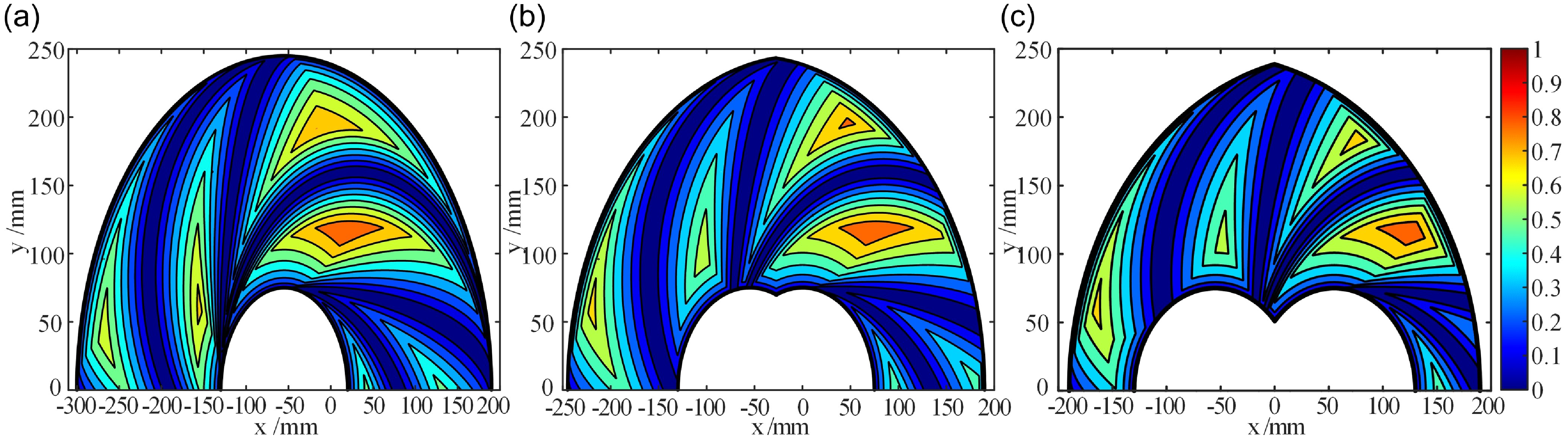
of closed-loop redundant limb 2 are set to −55, 0, and 55 mm, respectively, the corresponding LTI distributions are illustrated in Fig. 9. The types and distribution of singularities in the
 $\underline{\textrm{R}}{\textrm{RR}}-[\underline{\textrm{P}}{\textrm{R}}-\underline{\textrm{P}}{\textrm{R}}]{\textrm{RR}}$
mechanism are consistent with those of the
 $\underline{\textrm{R}}{\textrm{RR}}-\underline{\textrm{P}}\underline{\textrm{R}}{\textrm{RR}}$
mechanism described in Section 2.3.
LTI distribution of RRR-[PR-PR]RR PM: (a)
 $q_{1}=-\mathit{55}\, \text{mm}$
; (b)
 $q_{1}=\mathit{0}\, \text{mm}$
; (c)
 $q_{1}=\mathit{55}\, \text{mm}$
.

3. Optimization of inverse kinematics solutions for kinematically redundant parallel mechanisms
3.1. Local optimal transmission index
For a given position and orientation of the moving platform in a kinematically redundant PM, multiple actuated joint-space configurations may exist that satisfy the kinematic constraints. The collection of all such feasible configurations forms the inverse kinematics solution set, denoted as
 $\boldsymbol{Q}$
. For any solution
 $\boldsymbol{q}_{i}\in \boldsymbol{Q}$
, a LTI value
 $\gamma _{i}$
can be computed using the method described in Section 2. The maximum value among them defines the LOTI, expressed as
 \begin{equation} \gamma _{g}=\max \left\{\gamma _{i}\right\} \end{equation}
The LOTI value
 $\gamma _{g}$
is a dimensionless, coordinate-invariant index that lies within the range
 $[0,1]$
. A higher LOTI indicates better optimal transmission efficiency of motion/force at the given position and orientation of the mechanism.
3.2. Optimization of inverse kinematics solution
Due to the nonuniqueness of inverse kinematics solutions in kinematically redundant PMs, the LOTI is employed to optimize the inverse kinematics results. The actuated joint parameters
 $\boldsymbol{q}$
corresponding to the LOTI are defined as the optimal motion/force transmission solution for a given position and orientation of the moving platform and are denoted as
 $\boldsymbol{g}(\boldsymbol{g}\in \boldsymbol{Q})$
.Therefore, the optimization process for the inverse kinematics solution is as follows:
-
1. Select
$(m-n)$
redundant actuated joints (
$m$
represents the number of actuators, and
$n$
represents the DOFs of the moving platform), and determine their feasible actuation range
$[q_{\min },q_{\max }]$
. -
2. Discretize the actuation range of the
$(m-n)$
redundant joints into
$p_{i}$
groups with a step size
$h_{i}$
, yielding
$\prod _{i=1}^{(m-n)}p_{i}$
sets of parameter combinations. For each combination, compute the corresponding inverse kinematics solution
$\boldsymbol{q}$
, and collect them into the inverse kinematics solution set
$\boldsymbol{Q}$
. -
3. Compute the LTI for all inverse kinematics solutions in
$\boldsymbol{Q}$
, and identify the solution with the maximum LTI value
$\gamma _{g}$
as the optimal solution
$\boldsymbol{g}(\boldsymbol{g}\in \boldsymbol{Q})$
.


For example, the inverse kinematics solutions of the kinematically redundant PMs
 $\underline{\textrm{R}}{\textrm{RR}}-\underline{\textrm{P}}\underline{\textrm{R}}{\textrm{RR}}$
and
 $\underline{\textrm{R}}{\textrm{RR}}-[\underline{\textrm{P}}{\textrm{R}}-\underline{\textrm{P}}{\textrm{R}}]{\textrm{RR}}$
discussed in Sections 2.3 and 2.4 are optimized. The input parameter
 $q_{1}$
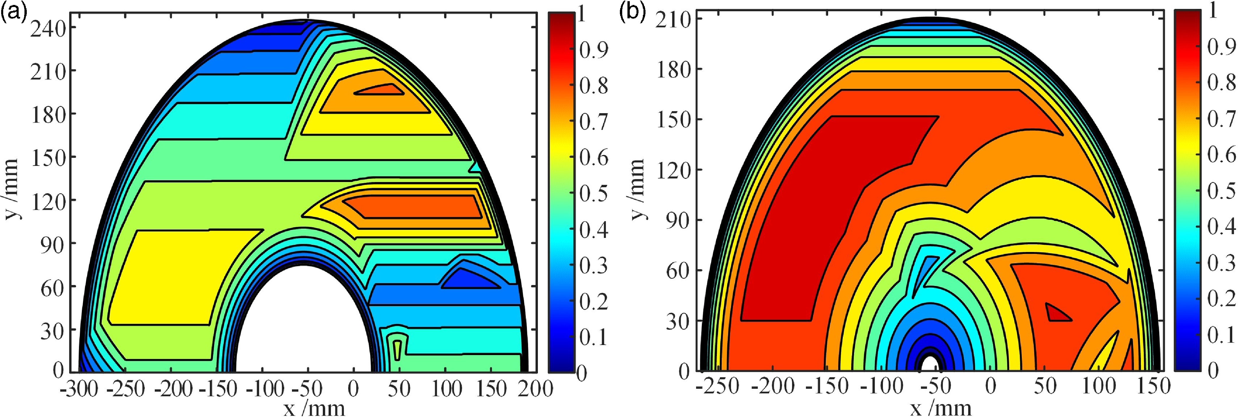
of the actuated P joint is discretized, resulting in the optimal inverse kinematics solutions throughout the entire workspace. The LTI distributions corresponding to these optimal solutions are shown in Figs. 10(a) and (b). Compared with Figs. 5 and 9, it can be observed that the singular configurations in the LTI distributions are significantly reduced after optimization, and the effective workspace is noticeably expanded.
LOTI distribution of the: (a)
 $\underline{R}RR-\underline{P}\underline{R}RR$
PM; (b)RRR-[PR-PR]RR PM.

It should be noted that in the offline trajectory planning of practical kinematically redundant PMs, the optimized inverse kinematic solutions may lack continuous differentiability due to the limited step size
 $h_{i}$
and abrupt performance variations near singular configurations. This may lead to discontinuities in position, as well as abrupt variations in joint velocity and acceleration. Therefore, a secondary optimization of the inverse kinematic solutions is required, incorporating constraints on actuated joint position, velocity, and acceleration to ensure continuous and smooth motion of the physical prototype.
3.3. Global transmission index
Due to the complex architecture of kinematically redundant PMs, their motion/force transmission performance is generally inferior to that of nonredundant PMs. To reasonably evaluate the motion/force transmission performance of kinematically redundant PMs, the good transmission workspace (GTW) is defined as LTI value
 $\gamma \geq 0.5$
(i.e., the transmission angle
 $\alpha$
satisfies
 $\alpha \in [30^{\circ },150^{\circ }]$
, the relationship between the transmission angle and the LTI is discussed in ref. [Reference H.39] ). Furthermore, the ratio of the GTW to the reachable workspace is defined as the Global Transmission Index (GTI) [Reference Liu, Wu and Wang26], expressed as
 \begin{equation} \sigma _{G}=\frac{\int _{{S_{G}}}\textrm{d}W}{\int _{S}\textrm{d}W} \end{equation}
where
 $\textrm{d}W$
represents a unit grid within the reachable workspace,
 $S_{G}$
and
 $S$
denote the areas of the GTW and the reachable workspace, respectively.
The GTI value
 $\sigma _{G}$
is a dimensionless, coordinate-independent metric ranging from 0 to 1. It quantifies the proportion of high-performance regions within the reachable workspace, thereby reflecting the overall motion/force transmission performance of the mechanism. A higher GTI value indicates better transmission characteristics throughout the workspace.
4. Application example
To validate the proposed motion/force transmission indices and the inverse kinematics solution optimization method, two types of (6 + 3)-DOF kinematically redundant PMs are analyzed.
4.1. The 3-PRRSR mechanism with general redundant limbs
The
 $3-\underline{\textrm{P}}\underline{\textrm{R}}\underline{\textrm{R}}\textrm{SR}$
kinematically redundant PM is derived by simplifying the
 $3-\underline{\textrm{P}}[\underline{\textrm{R}}{\textrm{R}}-\underline{\textrm{R}}{\textrm{RR}}]\textrm{SR}$
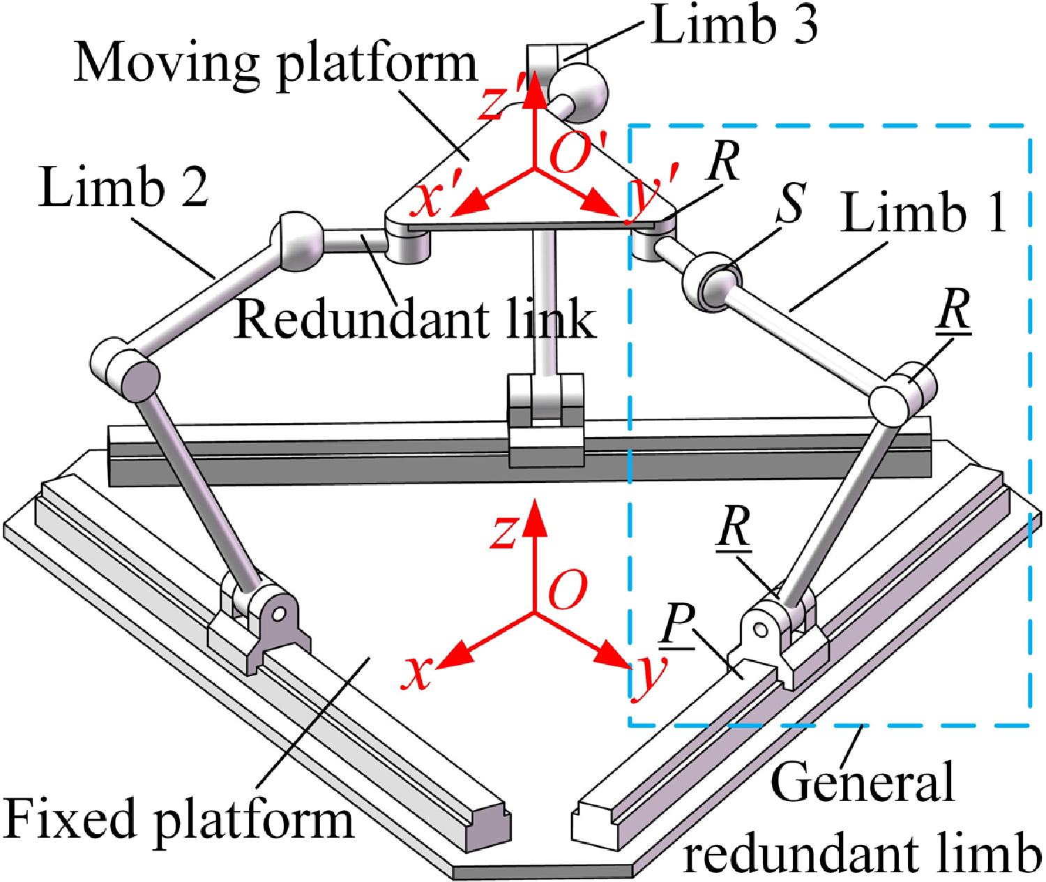
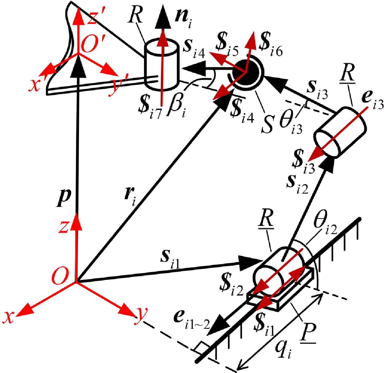
mechanism described in ref. [Reference Li, He, Zhang, Chen and Ye40]. It consists of a moving platform and three PRRSR redundant limbs, as shown in Fig. 11. A fixed coordinate frame
 $O-xyz$
is established on the fixed base, and a moving coordinate frame
 $O\mathit{'}-x\mathit{'}y\mathit{'}z\mathit{'}$
is defined on the moving platform. The general redundant limb
 $\underline{\textrm{P}}\underline{\textrm{R}}\underline{\textrm{R}}\textrm{SR}$
is simplified as illustrated in Fig. 12. In this figure,
 $\boldsymbol{p}$
represents the position vector of the moving platform origin
 $O\mathit{'}$
relative to the fixed base origin
 $O$
.
 ${\boldsymbol{s}}_{ij}(;i=1,2,3;\, j=2,3,4);$
denotes the vector of the
 $j\text{-}{\textrm{th}}$
link in the
 $i\text{-}{\textrm{th}}$
limb, and
 $l_{ij}$
denotes its corresponding length.
 ${\boldsymbol{r}}_{i}$
is the position vector of the spherical joint in the
 $i\text{-}{\textrm{th}}$
limb, and
 $\boldsymbol{n}_{i}$
is the direction vector of the passive R joint. The vectors
 $\boldsymbol{e}_{i1\sim 3}$
represent the direction vectors of the actuated P and R joint, respectively.
 $q_{i} , \theta _{i2}$
and
 $\theta _{i3}$
denote the input values of the P and R joints, and
 $\beta _{i}$
represents the redundant link angle.
The 3-
 $\underline{P}\underline{R}\underline{R}SR$
mechanism.

Schematic diagram of the
 $\underline{P}\underline{R}\underline{R}SR$
limb.

The twist screw system of the
 $ i\text{-}{\textrm{th}} \,\underline{\textrm{P}}\underline{\textrm{R}}\underline{\textrm{R}}\textrm{SR}$
limb of the mechanism is denoted by
 $\boldsymbol{U}_{i}=\{{\boldsymbol{\$}}_{i1},{\boldsymbol{\$}}_{i2},{\boldsymbol{\$}}_{i3},{\boldsymbol{\$}}_{i4},{\boldsymbol{\$}}_{i5},{\boldsymbol{\$}}_{i6},{\boldsymbol{\$}}_{i7}\}$
. Each screw in the system is expressed as follows:

where
 ${\boldsymbol{\$}}_{i1},{\boldsymbol{\$}}_{i2},{\boldsymbol{\$}}_{i3}$
are the input twist screws of actuated P and R joints, are the twist screws of spherical joint, is the twist screw of the passive R joint.
Then, the redundancy decomposition of the
 $i\text{-}{\textrm{th}}\, \underline{\textrm{P}}\underline{\textrm{R}}\underline{\textrm{R}}\textrm{SR}$
limb is carried out. When calculating the transmitted wrench screw corresponding to the actuated P joint, the two actuated R joints are considered rigidly fixed, and the limb is equivalently simplified to a
 $\underline{\textrm{P}}\textrm{SR}$
structure. Similarly, when both the P joint and the first or second R joint are fixed, the limb is simplified to a structure. The joint combinations and their corresponding twist screw systems for the equivalent limb are summarized in Table II.
The twist screw system of equivalent limb
 $i-1$
is denoted by
 $\boldsymbol{U}_{i1}=\{{\boldsymbol{\$}}_{i1},{\boldsymbol{\$}}_{i4},{\boldsymbol{\$}}_{i5},{\boldsymbol{\$}}_{i6},{\boldsymbol{\$}}_{i7}\}$
, and the transmission wrench screw corresponding to the actuated P joint is given by
 \begin{equation} {\boldsymbol{\$}}_{Ti1}=\left(\boldsymbol{f}_{i1}; \; {\boldsymbol{r}}_{i}\times \boldsymbol{f}_{i1}\right)=\left({\boldsymbol{s}}_{i4}/\left| {\boldsymbol{s}}_{i4}\right| ;\, {\boldsymbol{r}}_{i}\times \left({\boldsymbol{s}}_{i4}/\left| {\boldsymbol{s}}_{i4}\right| \right)\right) \end{equation}
where
 ${\boldsymbol{\$}}_{Ti1}$
represent a pure force along the direction of the redundant limb and pass through S joint.
Similarly, the transmission wrench screw corresponding to the actuated R joint in equivalent limb
 $i-2$
and
 $i-3$
is given by
 \begin{equation} {\boldsymbol{\$}}_{Ti2\left(Ti3\right)}=\left(\boldsymbol{f}_{i2\left(i3\right)}; \; {\boldsymbol{r}}_{i}\times \boldsymbol{f}_{i2\left(i3\right)}\right) \end{equation}
Given the transmission wrench screws
 ${\boldsymbol{\$}}_{Ti1} , {\boldsymbol{\$}}_{Ti2}$
and
 ${\boldsymbol{\$}}_{Ti3}$
defined in Eqs. (46) and (47), the corresponding output twist screws
 ${\boldsymbol{\$}}_{Oi1} , {\boldsymbol{\$}}_{Oi2}$
and
 ${\boldsymbol{\$}}_{Oi3}$
can be determined. According to Eq. (8), the input and output power coefficients for the
 $k\text{-}{\textrm{th}}$
actuated joint in
 $i\text{-}{\textrm{th}}$
limb are expressed as
 \begin{equation} \lambda _{ik}=\frac{\left| {\boldsymbol{\$}}_{ik}\circ {\boldsymbol{\$}}_{Tik}\right| }{\left| {\boldsymbol{\$}}_{ik}\circ {\boldsymbol{\$}}_{Tik}\right| _{\max }}; \quad \eta _{ik}=\frac{\left| {\boldsymbol{\$}}_{Oik}\circ {\boldsymbol{\$}}_{Tik}\right| }{\left| {\boldsymbol{\$}}_{Oik}\circ {\boldsymbol{\$}}_{Tik}\right| _{\max }}\left(i,k=1,2,3\right) \end{equation}
The joint combinations and the twist screw systems of equivalent limbs.

Notes: The numbers 1, 2, 3, 4, and 5 in parentheses represent the
 $\underline{\textrm{P}} , \underline{\textrm{R}} , \underline{\textrm{R}} , \textrm{S}$
, and
 ${\textrm{R}}$
joints of the
 $i\text{-}{\textrm{th}}$
limb, respectively.
According to Eqs. (9)–(11), the ITI, OTI and LTI of the
 $3-\underline{\textrm{P}}\underline{\textrm{R}}\underline{\textrm{R}}\textrm{SR}$
PM are defined as
 \begin{align} \lambda _{I} &= \min \left\{\lambda _{ik}\right\}; \quad \eta _{O}=\min \left\{\eta _{ik}\right\}\left(i,k=1,2,3\right) \end{align}
 \begin{align} \gamma &= \min \left\{\lambda _{I},\eta _{O}\right\} \end{align}
The LTI distribution of the
 $3-\underline{\textrm{P}}\underline{\textrm{R}}\underline{\textrm{R}}\textrm{SR}$
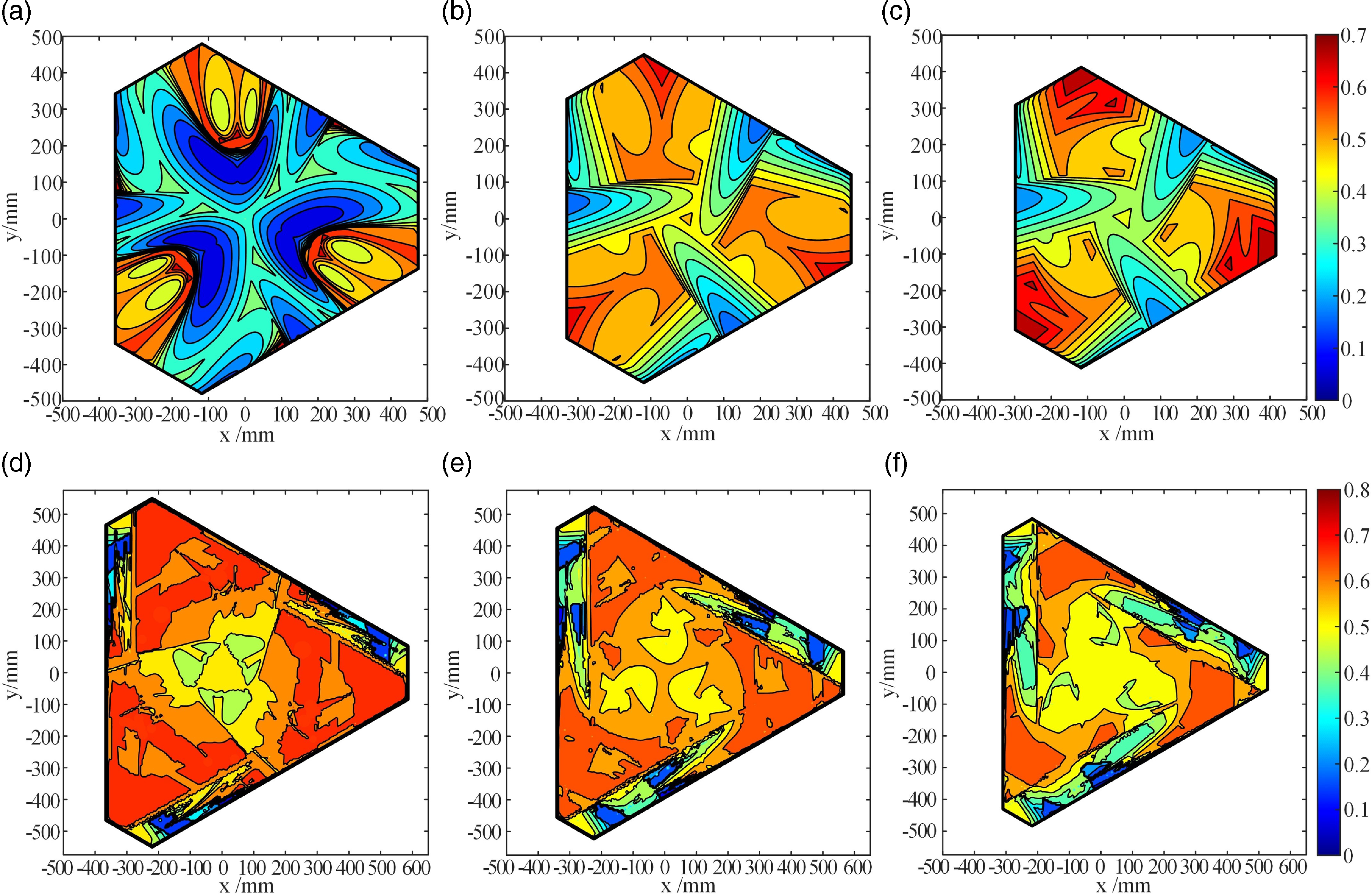
mechanism: before optimization: (a) z = 350 mm; (b) z = 400 mm; (c) z = 450mm; after optimization: (d) z = 350 mm; (e) z = 400 mm; (f) z = 450 mm.

The dimensions of the
 $j\text{-}{\textrm{th}}$
link of the
 $i\text{-}{\textrm{th}}$
limb in the
 $3-\underline{\textrm{P}}\underline{\textrm{R}}\underline{\textrm{R}}\textrm{SR}$
mechanism are given as
 $l_{i2}=300\text{ mm} , l_{i3}=150\text{ mm} , l_{i4}=75\text{ mm}$
. The radii of the fixed platform and the moving platform are specified as
 $r_{1}=220\text{ mm} , r_{2}=110\text{ mm}$
.The redundant angle
 $\beta _{i}$
is set to 47°, and the maximum stroke of the P joint is
 $L_{\max }=600\text{ mm}$
. When the pose parameters of the
 $3-\underline{\textrm{P}}\underline{\textrm{R}}\underline{\textrm{R}}\textrm{SR}$
mechanism are set to
 $\alpha =\beta =\gamma =0^{\circ }$
, the LTI distributions before and after optimization at Z-axis heights of 350, 400, and 450 mm of the moving platform are shown in Fig. 13. The corresponding GTI values and the reachable workspace areas of the mechanism before and after optimization are listed in Table III. As illustrated in Fig. 13 and Table III, the reachable workspace of the mechanism is significantly expanded through the optimization of the inverse kinematics solution. The GTI also shows significant improvement, demonstrating the effectiveness of the inverse kinematics solution optimization method.
GTI and reachable workspace areas of the moving platform at different z-axis heights.

Notes: The symbol
 $\sigma _{G1}$
and
 $\sigma _{G2}$
represent the LTI before and after optimization,
 $S_{1}$
and
 $S_{2}$
denote the reachable workspace areas before and after optimization.
4.2. The 3[UP-UP]RS-3UPS mechanism with closed-loop redundant limbs
The
 $3[\textrm{U}\underline{\textrm{P}}-\textrm{U}\underline{\textrm{P}}]\textrm{RS}-3\textrm{U}\underline{\textrm{P}}\textrm{S}$
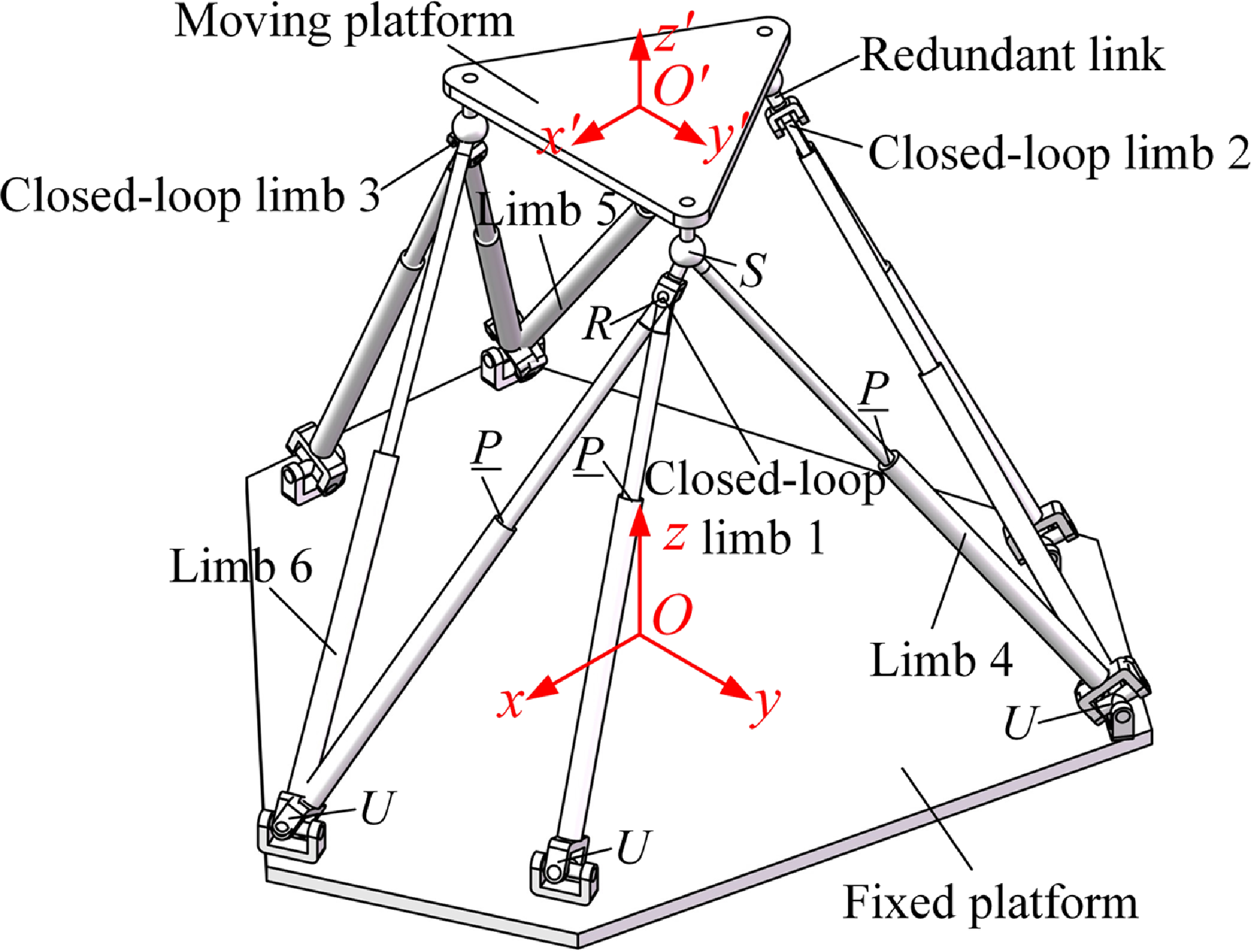
PM [Reference Gosselin and Schreiber19] consists of a fixed platform, a moving platform, three
 $[\textrm{U}\underline{\textrm{P}}-\textrm{U}\underline{\textrm{P}}]\textrm{RS}$
closed-loop redundant limbs, and three
 $\textrm{U}\underline{\textrm{P}}\textrm{S}$
nonredundant limbs, where
 $[\textrm{U}\underline{\textrm{P}}-\textrm{U}\underline{\textrm{P}}]{\textrm{R}}$
represents a closed-loop chain. The fixed coordinate
 $O-xyz$
and moving coordinate
 $O\mathit{'}-x\mathit{'}y\mathit{'}z\mathit{'}$
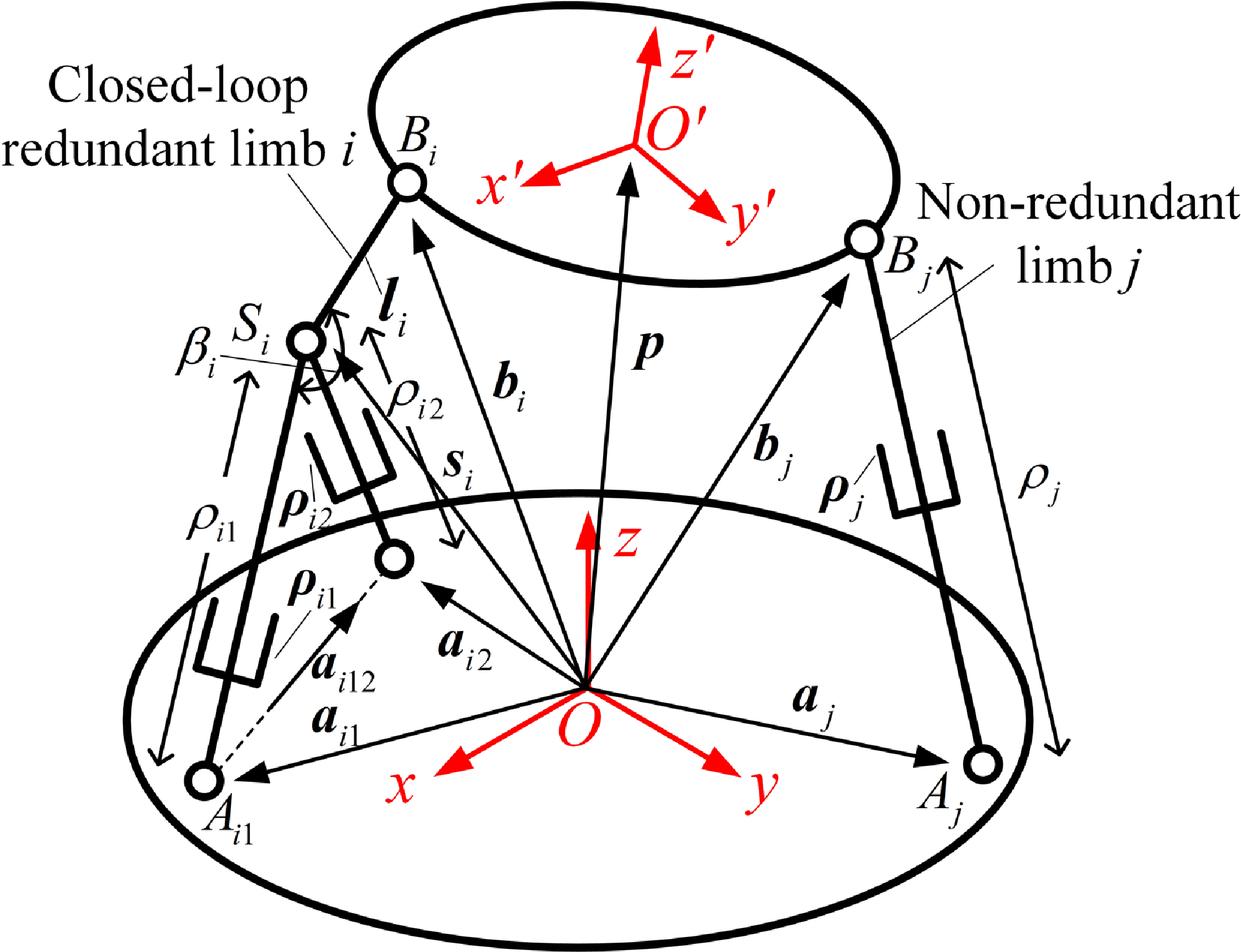
are, respectively, established as shown in Fig. 14. The structural schematic of the
 $i\text{-}{\textrm{th}} [\textrm{U}\underline{\textrm{P}}-\textrm{U}\underline{\textrm{P}}]\textrm{RS}$
limb and the
 $j-\textrm{thU}\underline{\textrm{P}}\textrm{S}$
limb of the mechanism is shown in Fig. 15. The vector
 $\boldsymbol{\rho }_{ik}(i=1,2,3;k=1,2)$
represents the link of the
 $k\text{-}{\textrm{th}}$
subchain in the
 $i\text{-}{\textrm{th}}$
closed-loop redundant limb, and the vector
 $\boldsymbol{\rho }_{j}(j=4,5,6)$
denotes the link of the
 $j\text{-}{\textrm{th}}$
nonredundant limb. The joint displacements of the actuated P joints are represented as
 $\mathit{\rho }_{ik}$
and
 $\mathit{\rho }_{j}$
, respectively. The vector
 $\boldsymbol{p}$
denotes the position of the moving platform origin with respect to the fixed platform origin
 $O$
.
 $\mathit{A}_{ik}$
and
 $\mathit{A}_{j}$
represent the intersection points of the joint axes of the U joints in the closed-loop redundant limb and the nonredundant limb, respectively. Their corresponding position vectors are
 $\boldsymbol{a}_{ik}$
and
 $\boldsymbol{a}_{j}$
.The spherical joints on the moving platform are denoted as
 $B_{i}$
and
 $\mathit{B}_{j}$
for the redundant and nonredundant limbs. Their position vectors are denoted as
 $\boldsymbol{b}_{i}$
and
 $\boldsymbol{b}_{j}$
. The compound joint in the closed-loop redundant limb is represented as
 $S_{i}$
, and its position vector is denoted as
 ${\boldsymbol{s}}_{i}$
.The redundant link angle is denoted by
 $\beta _{i}$
.
The 3[UP-UP]RS-3UPS PM.

Schematic diagram of 3[UP-UP]RS-3UPS PM.

The
 $3[\textrm{U}\underline{\textrm{P}}-\textrm{U}\underline{\textrm{P}}]\textrm{RS}-3\textrm{U}\underline{\textrm{P}}\textrm{S}$
mechanism is subjected to a redundancy decomposition process, in which the closed-loop chains
 $[\textrm{U}\underline{\textrm{P}}-\textrm{U}\underline{\textrm{P}}]{\textrm{R}}$
within the redundant limbs are decomposed into single DOF
 $\textrm{U}\underline{\textrm{P}}{\textrm{R}}-\textrm{UR}$
and
 $\textrm{UR}-\textrm{U}\underline{\textrm{P}}{\textrm{R}}$
mechanisms, referred to as second-level mechanisms. The remaining segments of the redundant limbs, together with the nonredundant limbs, are equivalently simplified into a unified
 $3\underline{\textrm{P}}\textrm{RS}-3\textrm{U}\underline{\textrm{P}}\textrm{S}$
mechanism, termed the first-level mechanism, as illustrated in Fig. 16.
Decomposing diagram of 3[UP-UP]RS-3UPS PM.

First, the second-level mechanisms, denoted as
 $\textrm{U}\underline{\textrm{P}}{\textrm{R}}-\textrm{UR}$
and
 $\textrm{UR}-\textrm{U}\underline{\textrm{P}}{\textrm{R}}$
, are analyzed. The transmission wrench screw
 ${\boldsymbol{\$}}_{Tik}$
of subchain
 $\textrm{U}\underline{\textrm{P}}{\textrm{R}}$
represents a pure force directed along P joint and passing through the U joint point
 $A_{ik}$
.Accordingly, the input twist screw
 ${\boldsymbol{\$}}_{Iik}$
and the corresponding transmission wrench screw of subchain
 ${\boldsymbol{\$}}_{Tik}$
can be expressed as follows:
 \begin{align} {\boldsymbol{\$}}_{Iik} &=\left(0; \; \boldsymbol{\rho }_{ik}\right) \end{align}
 \begin{align} {\boldsymbol{\$}}_{Tik} &=\left(\boldsymbol{f}_{ik}; \; {\boldsymbol{s}}_{ik}\times \boldsymbol{f}_{ik}\right) \end{align}
The output twist screws
 ${\boldsymbol{\$}}_{Oi1}$
and
 ${\boldsymbol{\$}}_{Oi2}$
of the second-level mechanisms
 $\textrm{U}\underline{\textrm{P}}{\textrm{R}}-\textrm{UR}$
and
 $\textrm{UR}-\textrm{U}\underline{\textrm{P}}{\textrm{R}}$
correspond to the reciprocal screws of their respective constraint screw systems, and are given by
 \begin{equation} {\boldsymbol{\$}}_{Oik}=\left(\boldsymbol{v}_{ik}; \; {\boldsymbol{s}}_{i}\times \boldsymbol{v}_{ik}\right)\left(k=1,2\right) \end{equation}
According to Eq. (8), the input and output power coefficients of the second-level mechanism are calculated as follows:
 \begin{align} \lambda _{ik} &=\frac{\left| {\boldsymbol{\$}}_{Iik}\circ {\boldsymbol{\$}}_{Tik}\right| }{\left| {\boldsymbol{\$}}_{Iik}\circ {\boldsymbol{\$}}_{Tik}\right| _{\max }}=\left| \boldsymbol{f}_{ik}\cdot \boldsymbol{\rho }_{ik}\right| \left(i=1,2,3;k=1,2\right) \end{align}
 \begin{align} \eta _{ik} &= \frac{\left| {\boldsymbol{\$}}_{Oik}\circ {\boldsymbol{\$}}_{Tik}\right| }{\left| {\boldsymbol{\$}}_{Oik}\circ {\boldsymbol{\$}}_{Tik}\right| _{\max }}=\left| \boldsymbol{v}_{ik}\cdot \boldsymbol{f}_{ik}\right| \left(i=1,2,3;k=1,2\right) \end{align}
For the first-level mechanism
 $3\underline{\textrm{P}}\textrm{RS}-3\textrm{U}\underline{\textrm{P}}\textrm{S}$
, the input twist screws of the
 $i\text{-}{\textrm{th}}$
equivalent
 $\underline{\textrm{P}}\textrm{RS}$
limb are derived from the output twist screws
 ${\boldsymbol{\$}}_{Oik}$
of the second-level mechanism
 $\textrm{U}\underline{\textrm{P}}{\textrm{R}}-\textrm{UR}$
. The corresponding transmission wrench
 ${\boldsymbol{\$}}_{Ti}$
screw represents a pure force passing through the spherical joint point
 $B_{i}$
and is expressed as
 \begin{align} {\boldsymbol{\$}}_{Ii} &={\boldsymbol{\$}}_{Oik}=\left(\boldsymbol{v}_{ik}; \; {\boldsymbol{s}}_{i}\times \boldsymbol{v}_{ik}\right) \end{align}
 \begin{align} {\boldsymbol{\$}}_{Ti} &=\left(\boldsymbol{f}_{i}; \; \boldsymbol{b}_{i}\times \boldsymbol{f}_{i}\right) \end{align}
Similarly, the input twist screw and the corresponding transmission wrench screw of the
 $j-\textrm{thU}\underline{\textrm{P}}\textrm{S}$
limb are defined as
 \begin{align} {\boldsymbol{\$}}_{Ij} &=\left(0; \; \boldsymbol{\rho }_{j}\right) \end{align}
 \begin{align} {\boldsymbol{\$}}_{Tj} &=\left(\boldsymbol{f}_{j}; \; \boldsymbol{b}_{j}\times \boldsymbol{f}_{j}\right) \end{align}
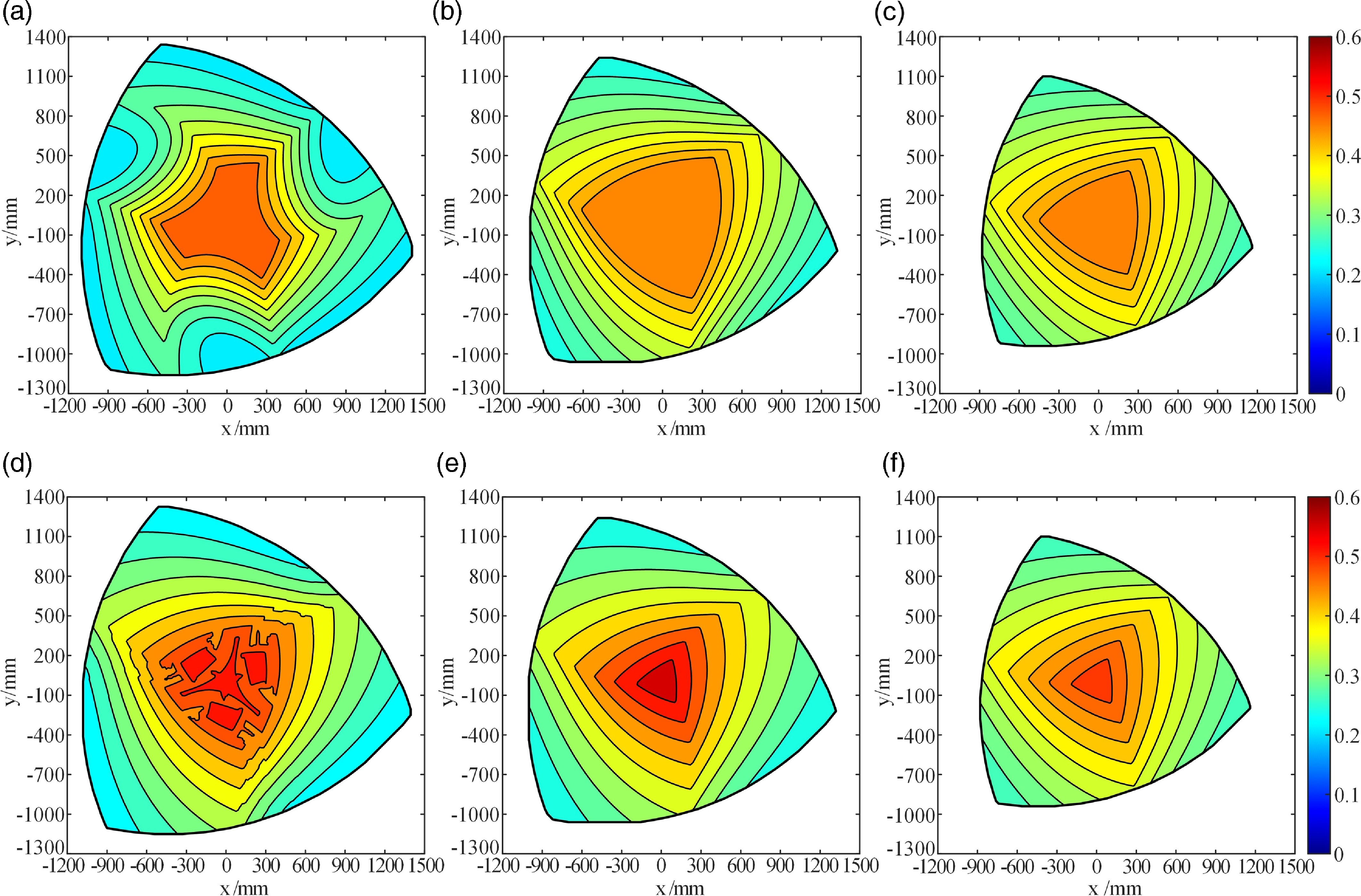
The LTI distribution of the 3[UP-UP]RS-3UPS PM: before optimization: (a) z = 700 mm; (b) z = 1000 mm; (c) z = 1300mm; after optimization: (d) z = 700 mm; (e) z = 1000 mm; (f) z = 1300mm.

According to Eqs. (57) and (59), the output twist screws
 ${\boldsymbol{\$}}_{Oi}$
and
 ${\boldsymbol{\$}}_{Oj}$
of the first-level mechanism
 $3\underline{\textrm{P}}\textrm{RS}-3\textrm{U}\underline{\textrm{P}}\textrm{S}$
can be obtained. Accordingly, the input and output power coefficients for the
 $i\text{-}{\textrm{th}}\, \underline{\textrm{P}}\textrm{RS}$
limbs and the
 $j\textrm{-th}\textrm{ U}\underline{\textrm{P}}\textrm{S}$
limb are given by:
 \begin{align} \lambda _{i} &=\frac{\left| {\boldsymbol{\$}}_{Ii}\circ {\boldsymbol{\$}}_{Ti}\right| }{\left| {\boldsymbol{\$}}_{Ii}\circ {\boldsymbol{\$}}_{Ti}\right| _{\max }}; \quad \lambda _{j}=\frac{\left| {\boldsymbol{\$}}_{Ij}\circ {\boldsymbol{\$}}_{Tj}\right| }{\left| {\boldsymbol{\$}}_{Ij}\circ {\boldsymbol{\$}}_{Tj}\right| _{\max }}\, \left(i=1,2,3; \; j=4,5,6\right) \end{align}
 \begin{align} \eta _{i} &=\frac{\left| {\boldsymbol{\$}}_{Oi}\circ {\boldsymbol{\$}}_{Ti}\right| }{\left| {\boldsymbol{\$}}_{Oi}\circ {\boldsymbol{\$}}_{Ti}\right| _{\max }}; \quad \eta _{j}=\frac{\left| {\boldsymbol{\$}}_{Oj}\circ {\boldsymbol{\$}}_{Tj}\right| }{\left| {\boldsymbol{\$}}_{Oj}\circ {\boldsymbol{\$}}_{Tj}\right| _{\max }}\, \left(i=1,2,3; \; j=4,5,6\right) \end{align}
Finally, the ITI, OTI and LTI of the
 $3[\textrm{U}\underline{\textrm{P}}-\textrm{U}\underline{\textrm{P}}]\textrm{RS}-3\textrm{U}\underline{\textrm{P}}\textrm{S}$
mechanism are defined as follows:
 \begin{align} \lambda _{I} &=\min \left\{\lambda _{ik},\lambda _{i},\lambda _{j}\right\}\left(i=1,2,3; \; j=4,5,6; \; k=1,2\right) \end{align}
 \begin{align} \eta _{O} &=\min \left\{\eta _{ik},\eta _{i},\eta _{j}\right\}\left(i=1,2,3; \; j=4,5,6; \; k=1,2\right) \end{align}
 \begin{align} \gamma &=\min \left\{\lambda _{I},\eta _{O}\right\} \end{align}
The redundant link length parameters of the
 $i\text{-}{\textrm{th}}$
closed-loop redundant limb in the
 $3[\textrm{U}\underline{\textrm{P}}-\textrm{U}\underline{\textrm{P}}]\textrm{RS}-3\textrm{U}\underline{\textrm{P}}\textrm{S}$
mechanism are given by
 $l_{i}=140\text{ mm}$
. The radii of the U joints on the fixed platform are specified as
 $r_{i1}=r_{j}=1400\text{ mm}$
and
 $r_{i2}=1220\text{ mm}$
. The radius of the S joints on the moving platform is set to
 $r_{1}=500\text{ mm}$
. The redundant angle
 $\beta _{i}$
is set to 210°, and the maximum stroke of the P joint is
 $L_{\max }=2800\text{ mm}$
. When the
 $3[\textrm{U}\underline{\textrm{P}}-\textrm{U}\underline{\textrm{P}}]\textrm{RS}-3\textrm{U}\underline{\textrm{P}}\textrm{S}$
mechanism is oriented in the
 $\alpha ,\beta ,\gamma =0^{\circ }$
configuration with three z-axis values set to 700 mm,1000 mm,1300 mm, the LTI distributions before and after optimization are illustrated in Fig. 17, respectively. The corresponding GTI values and reachable workspace areas before and after optimization are summarized in Table IV. Following optimization, the GTI of the mechanism shows significant improvement, indicating enhanced motion/force transmission performance.
The GTI and reachable workspace areas of moving platform at different z-axis values.

Notes: The symbol
 $\sigma _{G1}$
and
 $\sigma _{G2}$
are LTI before and after optimization.
 $S_{1}$
and
 $S_{2}$
represent the reachable workspace areas.
5. Conclusions
-
1. This article proposes a motion/force transmission index that is applicable to kinematically redundant PMs containing both general and closed-loop redundant limbs. Through hierarchical division and redundancy decomposition, the kinematically redundant PM is transformed into several nonredundant equivalent mechanisms. The power coefficients of each actuated joint, along with the ITI, OTI, and LTI of the entire mechanism, are then calculated, thereby enabling a comprehensive evaluation of the motion/force transmission performance of the kinematically redundant PM.
-
2. Since the inverse kinematics solution of kinematically redundant PMs is not unique, optimization is necessary. By employing the motion/force transmission index, the inverse kinematics solution
$\boldsymbol{g}$
is optimized to yield the optimal configuration. This optimized solution offers several advantages, including singularity avoidance, workspace expansion, and improved overall performance. It is important to note that the inverse kinematic solutions obtained through this optimization method may exhibit discontinuities or be nondifferentiable. Therefore, in practical offline trajectory planning of kinematically redundant PMs, this method should be integrated with constraints on the position, velocity, and acceleration of the actuated joints for secondary trajectory planning.

Author contribution
Licong Li and Xiang Jin jointly proposed the performance evaluation index and the inverse kinematic solution optimization method for the kinematically redundant parallel mechanism. Haifeng Zhang provided theoretical guidance, while Qiaohong Chen and Wei Ye were responsible for text proofreading.
Financial support
This study was supported by the National Natural Science Foundation of China (Grant No. 52275036 and 52375033), and the Natural Science Foundation of Zhejiang Province (Grant No. LD24E050003).
Competing interests
The authors declare that there are no conflicts of interest of this paper.
Ethical approval
None.