I. INTRODUCTION
Over the past decade, the use of zinc-coated steel sheet has increased significantly with continuously growing demand for use in appliances and automotive panels. Reference Pistofidis, Vourlias, Konidaris, Pavlidou, Stergiou and Stergioudis1,Reference Bicao, Jianhua, Xuping, Zhi and Fucheng2 In continuous galvanizing lines, immersed bath equipment (e.g., sink rolls, stabilizer rolls, etc.) is subjected to erosion–corrosion attack from molten zinc because of the relative flowing velocity between the immersed surface and liquid zinc. Reference Ajersch, Ilinca, Hétu and Goodwin3–Reference Zhang, Tang, Goodwin and Sexton6 This results in significant economic losses owing to maintenance and replacement of the eroded parts in continuous galvanizing lines. In general, the degradation rate of parts because of erosion–corrosion differs from the damage caused by individual components, i.e., erosion and corrosion. The strong interaction between fluid chemical corrosion and mechanical erosion occurs during erosion–corrosion and may cause accelerated material degradation. Reference Heitz7–Reference Kondo, Takahashi, Suzuki, Ishikawa, Hata, Qiu and Sekimoto9 As predicted, in an erosion–corrosion environment, the material loss rate (i.e., total erosion–corrosion rate R) can be expressed by Eq. (1) (Refs. Reference Islam, Farhat, Ahmed and Alfantazi10 and Reference Kwok, Cheng and Man11):
 $$R = R_{\rm{e}}^{\rm{p}} + R_{\rm{c}}^{\rm{p}} + {R_{{\rm{Inter}}}}\quad ,$$
where R is the material loss under erosion–corrosion conditions,
 $R_{\rm{e}}^{\rm{p}}$
is the material loss because of pure mechanical erosion,
 $R_{\rm{c}}^{\rm{p}}$
is the material loss because of pure chemical corrosion, and R
Inter is the interaction effect between erosion and corrosion.
Recently, much attention has been given to the interaction between erosion and corrosion (especially in the slurry industry). Reference Islam, Farhat, Ahmed and Alfantazi10–Reference Neville, Reyes and Xu14 Clark Reference Clark12 lists factors that influence this interaction and these can be categorized into four main areas, namely liquid characteristics, target material properties, particle properties, and flow field effects. Research by Finnie Reference Finnie13 indicates that erosion–corrosion interaction is dependent mainly on the number of particles striking the surface, the particle velocity, and the particle impact angle. Many investigations have also reported that the erosion–corrosion interaction relies strongly on fluid velocity. Reference Purandare, Stack and Hovsepian15–Reference Tian and Cheng18 The increasing slurry velocity accelerates the passive film removal rate, increases corrosion kinetics by creating subsurface cracks and deforming the work-hardened layer, and facilitates the corrosion reaction. This leads to a significant increase in corrosion rate. The corrosion reaction can remove work-hardened layers, and accelerate delamination by extending subsurface cracks. This results in an increased erosion rate. Based on these research results, the fluid velocity has a marked effect on the erosion–corrosion interaction. However, limited studies have been conducted on the effect of velocity factor on the erosion–corrosion interaction of flowing liquid zinc. An investigation into the effect of erosion speed on the interaction effect between erosion and corrosion in a flowing zinc bath would clarify the damage mechanism of the immersed bath equipment (e.g., sink rolls, stabilizer rolls, etc.) in a continuous galvanizing line.
A Fe–B alloy that contains 3.5 wt% B shows improved corrosion resistance to liquid zinc owing to its unique structure (i.e., two-phase microstructure with netlike anticaustic Fe2B phase plus ductile α-Fe matrix) and the nonwetting characteristic between molten zinc and Fe2B, which can generate an improved barrier effect to obstruct liquid zinc corrosion. Reference Ma, Xing, Fu, Yi, Zhang, Li, Zhang, Zhu and Ma19–Reference Ma, Xing, Yi, Fu, Liu and Ma21 The Fe–3.5 wt% B alloy could therefore be used to manufacture parts and components in galvanizing equipment.
The effect of erosion speed on the interaction between erosion and corrosion of the Fe–3.5 wt% B alloy in a flowing zinc bath has therefore been investigated. The pure corrosion rate was measured by corrosion tests in static liquid zinc and the total erosion–corrosion rate was obtained from erosion–corrosion tests in flowing liquid zinc. Based on previous study, 0.25 wt% Al addition into static liquid zinc bath can result in a very slow corrosion rate for the Fe–B alloy. Reference Ma, Xing, Fu, Yi, Li, Zhang, Zhu and Gao22 Furthermore, Liu and Ghuman et al. investigated the corrosion of various materials under static and dynamic conditions and pointed out that 0.3 wt% Al may lead to a proper reducing corrosion rate under dynamic condition. Reference Liu, Barbero, Xu, Burris, Chang and Sikka4,Reference Ghuman and Goldstein23 Considering these facts, the pure erosion rate, therefore, was assessed using an erosion–corrosion test in flowing zinc with 0.3 wt% Al addition (i.e., corrosion-inhibition test). The erosion–corrosion interaction components were determined at various erosion speeds, the erosion–corrosion interaction rate was estimated, and the effect of erosion speed on the interaction between liquid zinc erosion and corrosion was discussed.
II. MATERIALS AND METHODS
A. Materials and specimen preparation
The tested material was melted in a 10 kg-capacity medium frequency induction furnace. In the early stage, clean pure iron, the Fe–19.80 wt% B ferro-alloy as well as steel scrap were added to the furnace and a little Al was added to slag-free molten steel to minimize the oxidation loss and slag formation. The melt was subsequently heated to 1550–1600 °C and then poured at 1420 °C into a dry sand mold to obtain a Y-type ingot. Eventually, the as-cast Y-type ingot was cleaned and cut into the desired erosion–corrosion specimens with dimensions of 120 mm × 15 mm × 5 mm by wire electric discharge machine. The chemical composition of the investigated Fe–3.5 wt% B alloy analyzed by spark emission spectrometer is listed in Table I.
Chemical composition of the investigated Fe–B alloy.

B. Erosion–corrosion test in flowing zinc
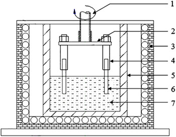
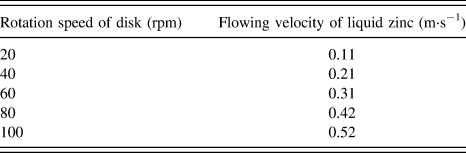
A schematic map of the erosion–corrosion tester is shown in Fig. 1. Before the erosion–corrosion test, all the specimens were ground using 2000 mesh carborundum paper and cleaned ultrasonically in acetone. The initial thickness between two side faces of the tested specimen was obtained from an average value measured ten times at multiple locations using a micrometer. To ensure that iron in the liquid zinc was unsaturated, 30 kg pure zinc (99.99 wt%) was melted (i.e., the volume of liquid zinc is about 4.6 × 10⁻³ m3) in an alumina crucible in each erosion–corrosion test, and a K-type thermocouple was immersed into the liquid zinc to monitor the temperature. The erosion–corrosion tests in a 460 °C liquid zinc bath with and without 0.3 wt% Al were carried out under dynamic conditions, and the erosion angle and test time were 0° and 5 h, respectively. The erosion speed ranged from 20 to 100 rpm at an interval of 20 rpm. The relationship between erosion speed (i.e., disk rotation speed) and flow velocity of liquid zinc is shown in Table II. The total erosion–corrosion rate was obtained from an erosion–corrosion test in a flowing zinc bath. Based on the estimation equation of inhibition efficiency, Reference Wang, Li, Ying, Wang, Xiao and Chen24 the inhibition efficiency of 0.3 wt% Al addition in a flowing zinc bath is 89.37% at 460 °C flowing liquid zinc. Therefore, the pure erosion rate was measured by a corrosion-inhibition test in flowing zinc with 0.3 wt% Al as an inhibitor. The pure corrosion test in a 460 °C liquid zinc bath under static conditions was used to determine the pure corrosion rate. After each specimen was tested for 5 h, it was removed from the liquid zinc and embedded in resin. The thickness of each erosion–corrosion specimen was measured microscopically at 1-mm-interval across the cross-section. The following equation was used to calculate the erosion–corrosion rate of the tested alloy Reference Liu, Barbero, Xu, Burris, Chang and Sikka4,Reference Ma, Xing, Yi, Fu, Liu and Ma21 :
 $$R = {{a - b} \over {2t}}\quad ,$$
where R is the erosion–corrosion rate (μm·h−1), a is the original thickness (μm), b is the final thickness (μm), and t is the test time (h). The factor of 1/2 in Eq. (2) shows that the average change in specimen thickness is caused by erosion–corrosion of both faces of the specimen.
Schematic diagram of the erosion–corrosion testing device: 1 – erosion shaft; 2 – disk for controlling erosion angle; 3 – furnace; 4 – specimen holder; 5 – crucible; 6 – test specimen; 7 – liquid zinc.

The relationship of rotation speed of disk and flowing velocity of liquid zinc.

C. Microstructure characteristics
The interfacial microstructure of the erosion–corrosion specimen was carried out by using a scanning electron microscopy (Tescan VEGA II XMU, Brno, Czech Republic), a backscattered electron image, an energy dispersive spectrometer (EDS). The metallographic analysis of the as-cast specimen was performed on LEICA DMI5000M (Wetzlar, Germany). Phase analysis of the as-cast specimen was undertaken by XRD in a MXP21VAHF diffractometer using copper Kα radiation coupling continuous scanning in 2θ ranging from 20° to 80° with current flow of 200 mA and electric voltage of 40 kV and scanning speed of 2°/min and step space of 0.02°.
III. RESULTS
A. As-cast microstructure of the Fe–3.5 wt% B alloy
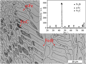
Figure 2 shows the as-cast structure and x-ray diffractometry pattern of the investigated Fe–3.5 wt% B alloy. The microstructure of the Fe–3.5 wt% B alloy is composed mainly of ferrite, some amount of netlike eutectic Fe2B, and some Fe3C (as shown in Fig. 2). The eutectic Fe2B phase is distributed continuously over the metallic matrix.
As-cast microstructures and XRD pattern of the Fe–3.5 wt% B alloy.

B. Erosion–corrosion components at various erosion speeds
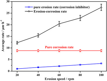
Figure 3 shows the total erosion–corrosion rate, pure erosion rate, and pure corrosion rate of the Fe–3.5 wt% B alloy in flowing liquid zinc as a function of erosion speed. The effect of erosion speed on the total erosion–corrosion rate is most pronounced, followed by the pure erosion rate. The total erosion–corrosion rate increases rapidly with erosion speed from 20 to 100 rpm, whereas the pure erosion rate (i.e., under corrosion-inhibition conditions) tends to increase linearly and gently from 1.11 to 3.33 μm·h−1 at a low damage level. The increase in erosion speed causes an obvious increase in total erosion–corrosion rate, but has little influence on the pure erosion rate. The rapid increase in total erosion–corrosion rate may be ascribed to the interaction between erosion and corrosion. Moreover, the pure corrosion rate retains constant at different erosion speeds (as shown in Fig. 3). With an increase in erosion speed, the difference between total erosion–corrosion and pure erosion and corrosion rates increases significantly. This may imply that the increase in erosion speed strengthens the interaction between erosion and corrosion.
The interaction components as a function of erosion speed.

C. Erosion–corrosion interaction rate at various erosion speeds
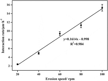
Based on Fig. 3 and Eq. (1), the interaction rate of liquid zinc erosion and corrosion of the Fe–3.5 wt% B alloy in flowing zinc can be estimated at various erosion speeds (as shown in Fig. 4). The erosion–corrosion interaction rate depends strongly on erosion speed. It increases linearly and increases from 2.41 to 15.34 μm·h−1 with the increase in erosion speed from 20 to 100 rpm.
The relationship between interaction rate and erosion speed.

IV. DISCUSSION
A. Effect of erosion speed on erosion–corrosion behavior of the Fe–3.5 wt% B alloy in flowing zinc
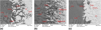
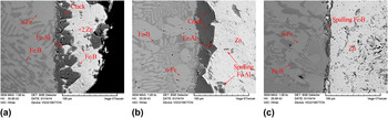
Figure 5 shows the interfacial morphologies of Fe–3.5 wt% B in a 460 °C flowing liquid zinc bath without Al at various erosion speeds. From Fig. 5(a), it can be seen that much of the residual anticaustic Fe2B skeleton with a few cracks of 60 μm depth is retained at the erosion–corrosion interface owing to the micromechanical scouring and corrosion effect by flowing liquid zinc at an erosion speed of 20 rpm. Little FeZn13 is observed in the erosion–corrosion interface. The mass of initial loose FeZn13 compound that was formed may be scoured away rapidly by flowing liquid zinc, Reference Ma, Xing, Fu, Yi, Zhi and Li20 which leads to a remnant FeZn10 layer with good adhesion adjacent to the substrate [as shown in Fig. 5(a)]. The anticaustic Fe2B skeleton zone without the support of an iron matrix corroded by liquid zinc becomes wide, and the corrosion products are reduced in front of the erosion–corrosion interface as the erosion speed increases to 60 rpm [as shown in Fig. 5(b)]. A mass of microcracks is observed in the residual anticaustic Fe2B skeleton near the substrate. Spallation of the Fe2B skeleton close to the liquid zinc also occurs because of enhanced micromechanical scouring effect. Accordingly, accelerated material degradation of the Fe–3.5 wt% B alloy occurs at 60 rpm (as shown in Fig. 3). Figure 5(c) shows that minimal protruded residual Fe2B skeleton exists in front of the erosion–corrosion interface as the erosion speed increases to 100 rpm. Instead, a wide corrosion product layer that consists of spalling Fe2B skeleton, FeZn10 mass, and loose and blocky FeZn13 with tetragonal morphology is visible. This may be ascribed to the combined action of more severe chemical corrosion and violent micromechanical effects of flowing zinc caused by an increase in erosion speed, which leads to the formation of a mass of corrosion products and subduction of a protruded anticaustic Fe2B skeleton zone. Finally, it causes an increased erosion–corrosion rate of the Fe–3.5 wt% B alloy at 100 rpm (as shown in Fig. 3).
Interfacial morphologies of the Fe–3.5 wt% B alloy in a 460 °C flowing zinc bath at various erosion speeds: (a) 20 rpm; (b) 60 rpm; (c) 100 rpm.

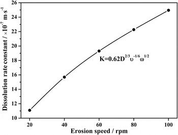
Figures 5(a) and 5(b) show that the increase in erosion speed accelerates the transfer process, which reduces corrosion products in the erosion–corrosion interface and causes accelerated material loss, consistent with the literature. Reference Kondo, Muroga, Sagara, Valentyn, Suzuki, Terai, Takahashi, Fujii, Yokoyama and Miyamoto8,Reference Fujiwara, Domae, Yoneda and Inada25 However, a thick corrosion product layer is visible in front of the erosion–corrosion interface at 100 rpm, which is very different from the interfaces at 20 and 60 rpm. This implies that a more severe iron–zinc corrosion reaction occurs at 100 rpm. The formation rate of corrosion products is more rapid than its removal rate. Based on previous investigations, Reference Giorgi, Durighello, Nicolle and Guillot26–Reference Kassner28 an increase in erosion speed accelerates the dissolution process, and the relationship between the erosion speed and dissolution rate constant is shown in Fig. 6. The more reactive corrosion of the α-Fe matrix and liquid zinc occurs with an increase in erosion speed, which yields a mass of Fe–Zn compounds. As indicated by Silverman, Reference Silverman29 the shear stress of flowing liquid acting on the steel surface is:
 $$\tau = 0.0791\,{R_{\rm{e}}}\rho r{\omega ^{2.3}}\quad ,$$
where τ is the shear stress (Pa), R e is the Reynolds number, ρ is the solution density (kg·m−3), r is the radius of the sample rotation (m), and ω is the erosion speed (rad·s−1). The shear stress is sensitive to the erosion speed. The high erosion speed of flowing zinc can therefore cause an extremely intense micromechanical effect, which impacts the residual anticaustic Fe2B skeleton and leads to rapid spallation of protruded and residual Fe2B skeleton. Simultaneously, a strong transfer process makes spalling Fe2B skeletons disappear completely in front of an erosion–corrosion interface at 100 rpm. The spallation and disappearance of an anticaustic Fe2B skeleton would facilitate new contact and a further corrosion reaction of Fe/Zn in flowing liquid zinc. Therefore, the accelerated dissolution and spallation of the Fe2B skeleton contribute to the severe corrosion reaction and facilitate erosion–corrosion at high erosion speeds, thereby causing large erosion–corrosion rates.
The relationship between dissolution rate constant and erosion speed. Reference Giorgi, Durighello, Nicolle and Guillot26–Reference Kassner28

Figure 5 indicates that the increasing erosion speed can facilitate erosion–corrosion. From Eq. (3), the shear stress produced by flowing zinc acting on the specimen surface is enhanced as the erosion speed increases. An extremely intense micromechanical effect that acts on the erosion–corrosion interface can occur with increase in erosion speed, impact on corrosion products and a residual anticaustic Fe2B skeleton, and deterioration of erosion–corrosion interfacial structures (as shown in Fig. 5). Corrosion processes can be facilitated and the accelerated corrosion reaction causes high mass transfer, heavy thickness loss, and further formation of products, which in turn promotes further removal of corrosion products and interfacial damage owing to the intensified micromechanical scouring effect. Therefore, the stronger erosion–corrosion process may occur naturally as the erosion speed increases, thereby leading to rapid material degradation of the Fe–3.5 wt% B alloy.
B. Role of corrosion in the erosion–corrosion process
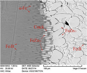
Previous investigations show that the static corrosion rate can be considered to be the pure corrosion component when investigating the interaction effect between erosion and corrosion. Reference Chakraborty, Basak and Chatterjee30–Reference Zheng, Yao, Wei and Ke32 Therefore, the pure corrosion rate of Fe–3.5 wt% B is maintained constant at various erosion speeds (as shown in Fig. 3). Figure 7 shows the interfacial morphology of the Fe–3.5 wt% B alloy in 460 °C static liquid zinc. An obvious feature is a loose corrosion layer containing little FeZn10, and a mass of block and loose FeZn13 with tetragonal morphology is observed in front of the corrosion interface. Based on the research by Song et al., Reference Song and Sloof33,Reference Song, Vystavel, van der Pers, De Hosson and Sloof34 the adhesive work of the FeZn13/Zn interface is lowest among all interfaces. This indicates that outer corrosion compounds (i.e., FeZn13) can be removed easily owing to the micromechanical scouring effect produced by flowing zinc under erosion conditions. The severe corrosive reaction of the matrix of the Fe–3.5 wt% B alloy roughens the surface by generating loose Fe–Zn corrosion compounds. The preferential corroded matrix would act as the weakest site for accelerated material loss under erosion conditions, which promotes an erosion–corrosion process. Some cracks also form in the netlike Fe2B skeleton owing to different thermal expansion coefficients among various phases in the corrosion interface. Reference Ma, Xing, Fu, Yi, Zhi and Li20,Reference Seong, Hwang, Kim and Kim35 In this case, the netlike Fe2B skeleton can be more vulnerable to micromechanical scouring from flowing liquid zinc under erosion conditions, and the barrier effect of the anticaustic Fe2B skeleton is reduced visibly. Violent corrosion of liquid zinc and the matrix occurs, which results in strong erosion–corrosion followed by accelerated material loss. According to the above analyses, corrosion can accelerate the erosion–corrosion of the Fe–3.5 wt% B alloy in a flowing liquid zinc bath by generating loose corrosion products and cracks in the anticaustic Fe2B skeleton.
Interfacial morphology of the Fe–3.5 wt% B alloy in 460 °C static liquid zinc.

C. Effect of erosion speed on pure erosion rate
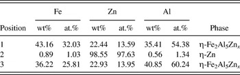
Generally, an enhancement in erosion speed is sensitive to the micromechanical effect of flowing zinc, which leads to a slight increase in pure erosion rate during erosion–corrosion (as shown in Fig. 3). Figure 8 shows the interfacial morphologies of the Fe–3.5 wt% B alloy in flowing liquid zinc with 0.3 Al wt% addition (i.e., under corrosion-inhibition conditions) at various erosion speeds. The phase compositions measured by energy dispersive spectroscopy in Fig. 8 are given in Table III. A continuous and uniform inhibition layer adjacent to the substrate of the Fe–3.5 wt% B alloy is observed at an erosion speed of 20 rpm [as shown in Fig. 8(a)]. Based on the compositional results in Table III and research by Marder, Reference Marder5 it is known that the inhibition layer is composed mainly of Fe2Al5Zn x . In this case, the α-Fe matrix of the Fe–3.5 wt% B alloy is hardly corroded by liquid zinc. It indicates that the corrosion of α-Fe matrix and zinc can be inhibited by adding 0.3 wt% Al into a flowing zinc bath. A mass of spalling anticaustic Fe2B and a broken inhibition layer are visible in the erosion layer owing to the micromechanical scouring effect of flowing zinc. As the erosion speed increases to 60 rpm, the inhibition layer breaks and some fragmented inhibition layers and spalling of the Fe2B skeleton results. This can be attributed to the enhanced micromechanical scouring effect of flowing zinc, which leads to an accelerated transfer process [as shown in Fig. 8(b)]. From Fig. 8(c), it can be seen clearly that the inhibition layer fractures and disappears completely and some spalling Fe2B skeleton exists in front of the erosion interface at 100 rpm, which indicates that an extremely intense micromechanical effect produced by flowing zinc is generated at 100 rpm, and leads to complete spallation of the inhibition layer and a strong transfer process.
Interfacial morphologies of the Fe–3.5 wt% B alloy in a 460 °C flowing zinc bath with 0.3 wt% Al addition at various erosion speeds: (a) 20 rpm; (b) 60 rpm; (c) 100 rpm.

The composition results of the phases measured by EDS analysis in Fig. 8.

According to Fig. 8, the inhibition layer suppresses the corrosion reaction of the α-Fe matrix and zinc and restricts fragmentation and spallation of the Fe2B skeleton, which creates some material degradation of the Fe–3.5 wt% B alloy in the flowing zinc bath with 0.3 wt% Al addition (as shown in Fig. 3). The improved erosion intensity caused by the erosion speed can therefore not cause rapid material degradation under individual erosion conditions. During erosion–corrosion of the Fe–3.5 wt% B alloy in flowing zinc, the large and accelerated material loss rate can be attributed to the interaction of an intensified mechanical effect and severe chemical corrosion because of an increase in erosion speed.
D. Effect of erosion speed on the interaction effect between liquid zinc erosion and corrosion
According to the above analyses, liquid zinc erosion accelerates the removal of corrosion products. Zinc corrosion also facilitates erosion by forming a loose corrosion layer, which leads to a strong interaction between liquid zinc erosion and corrosion and a corresponding rapid material loss of the Fe–3.5 wt% B alloy compared with that under individual erosion or corrosion conditions. The erosion speed has a marked effect on the erosion–corrosion interaction of liquid zinc of the Fe–3.5 wt% B alloy in a flowing zinc bath (as shown in Fig. 4). According to Figs. 5 and 8, the increase in erosion speed can intensify the micromechanical scouring effect acting on the erosion–corrosion interface of the Fe–3.5 wt% B alloy. This impacts the corrosion products and residual anticaustic Fe2B skeleton, deteriorates interfacial structures, and accelerates the removal of corrosion compounds and spallation of the anticaustic Fe2B skeleton. New contact between liquid zinc and the iron matrix of the Fe–3.5 wt% B alloy occurs and the interfacial corrosion reaction can be aggravated. Accelerated corrosion causes large mass transfer, heavy thickness losses, and additional formation of corrosion products, which improves further removal of corrosion products and interfacial damage because of the micromechanical effect of flowing liquid zinc. The increase in erosion speed can intensify the micromechanical effect of flowing zinc, lead to the accelerative destruction of interfacial layers and anticaustic Fe2B skeleton, and aggravate the zinc corrosion reaction. This results in many of the Fe–Zn compounds and residual anticaustic Fe2B skeleton losing the supporting effect of the iron matrix corroded by liquid zinc. Therefore, a stronger erosion–corrosion interaction occurs naturally as the erosion speed increases.
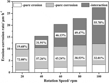
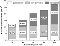
Figure 9 shows the contributions of individual factors (i.e., pure corrosion, pure erosion, and interaction) to the total erosion–corrosion rate of the Fe–3.5 wt% B alloy in a flowing zinc bath at various erosion speeds. The percentage interaction rate to total erosion–corrosion rate increases significantly from 19.68 to 55.78% as the erosion speed increases from 20 to 100 rpm, whereas the percentage of pure corrosion rate declines rapidly from 72.08 to 32.01%. The percentage of pure erosion changes from 8.22 to 12.11% with an increase in erosion speed. This implies that single erosion cannot result in the rapid material loss of the Fe–3.5 wt% B alloy, and pure corrosion is the main factor that causes material degradation under low erosion speed conditions. The enhancement of erosion because of the increase in erosion speed facilitates the interaction between liquid zinc erosion and corrosion. As a result, the interaction effect between liquid zinc erosion and corrosion has gradually become a dominant factor that causes material loss of the Fe–3.5 wt% B alloy as the erosion speed increases.
The percentage of pure erosion, pure corrosion, and interaction to the total erosion–corrosion rate as a function of erosion speed.

V. CONCLUSIONS
This study was carried out to investigate the effect of erosion speed on the interaction between erosion and corrosion of the Fe–3.5 wt% B alloy in a liquid zinc bath. The following conclusions were made.
-
(1) The total erosion–corrosion rate of the Fe–3.5 wt% B alloy increases linearly, but the pure erosion rate fluctuates slightly with an increase in erosion speed, which is strongly dependent on erosion–corrosion interaction.
-
(2) Severe chemical corrosion reactions facilitate erosion by forming a loose corrosion layer comprised of FeZn10 and FeZn13 and cracks in the anticaustic Fe2B skeleton.
-
(3) The increase in erosion speed intensifies the micromechanical effect of flowing zinc, accelerates the removal of corrosion products and the spallation of anticaustic Fe2B skeleton, deteriorates the erosion–corrosion interface, and aggravates corrosion of the α-Fe matrix of the Fe–3.5 wt% B alloy and liquid zinc.
-
(4) The erosion speed has a significant effect on the erosion–corrosion interaction, and the percentage interaction rate to total erosion–corrosion rate is approximately 55.78% at an erosion speed of 100 rpm. The enhancement in erosion facilitates the interaction between erosion and corrosion.
ACKNOWLEDGMENTS
The authors thank the financial support for this work from the Natural Science Foundation of China under Grant Nos. 51301128 and 51271142, the Specialized Research Fund for the Doctoral Program of Higher Education of China under Grant Nos. 20120201120005 and 20110201130008, the National Science Foundation for Post-doctoral Scientists of China under Grant Nos. 2012M521767 and 2013T60875, the Natural Science Foundation of Shaanxi Province under Grant No. 2014JQ7281, the Shaanxi provincial post-doctoral research project, the Fundamental Research Funds of Xi'an Jiaotong University under Grant Nos. xjj2013038 and xjj2014167, and the State Key Laboratory for Mechanical Behavior of Materials (No. 20141602).