I. INTRODUCTION
The field of biomaterial technology is gaining interest for the past few decades due to its advancement in the field of biomedical research by developing metallic, bioceramic, and polymeric implants.Reference Holzapfel, Reichert, Schantz, Gbureck, Rackwitz, Noth, Jakob, Rudert, Groll and Hutmacher1 Bioceramics are one of the most predominant biomaterial, which can be used for various orthopedic-related diseases to repair or replace damaged part of the tissue.Reference Thamaraiselvi and Rajeswari2,Reference Vallet-Regi3 Today, they play an important role in orthopedic marketReference Rieger, Leyen, Kobel and Weber4 because of the biocompatibility and osseointegration property, and mostly due to their similarity to mineral component of bones [hydroxyapatite (HAp)].Reference Vallet-Regi3 In addition, some bioceramic materials are chemically nonreactive and bioinert, as a result, they are nontoxic to body. However, not all bioceramics are chemically inert and may trigger host-bone response.Reference Hench and Wilson5
Crystalline HAp is a naturally occurring mineral component of bone and can be applied as coating to provide osteoconductivity, that promotes attachment and proliferation of osteoblast cells.Reference Lin, De Groot, Wang, Hu, Wismeijer and Liu6 Despite its long clinical use and even with evidence of good osteoconductivity,Reference LeGeros7 mixed results had been observed regarding osseointegration with HAp-coated implantsReference Zhang, Myers, Wallace, Brandt and Choong8 including coating failures. Due to poor mechanical properties (compressive strength in case of dense or porous scaffolds or elastic properties in case of coatings), HAp alone cannot be used for load-bearing bone implants. Commercial or available metallic implants [316L stainless steel (SS), titanium, Ti–6Al–4V, etc.] are having better elasto–plastic properties but the ability to form bond with tissue is low. So, to obtain both bioactivity and strength, the coating of HAp on metallic implants is considered a good approach.Reference Babu, Manwatkar, Rao and Kumar9 Moreover, alternative ceramic coatings or biphasic calcium phosphates or HAp with active biologic or pharmacologic agents have been explored to enhance the performance.Reference He, Huang, Gan, Zhou, Jiang, Wu, Wu and Gu10,Reference Saran, Zhang and Turcotte11
Chitosan is a biocompatible and biodegradable natural polysaccharide biopolymer synthesized from marine crustacean shells.Reference Kargupta, Bok, Darr, Crist, Gangopadhyay, Gangopadhyay and Sengupta12 It is an important biocompatible biopolymer having various reported applications including drug delivery and bacteriostatic properties and can also be used as coating.Reference Bumgardner, Wiser, Gerard, Bergin, Chestnutt, Marini, Ramsey, Elder and Gilbert13,Reference Correlo, Boesel, Bhattacharya, Mano, Neves and Reis14 It has been demonstrated that chitosan/polyvinyl alcohol composites improved coating stability and adhesion and also reported that elastic modulus could be adjusted by changing the concentration of chitosan in films to closely matched modulus of bone.Reference Mishra and Kannan15 Polyelectrolyte multilayer coatings of chitosan/hyaluronic acid (Chi/HA) and chitosan/gelatin (Chi/Gel) also improved the shear strength of titanium alloys.Reference Zankovych, Diefenbeck, Bossert, Muckley, Schrader, Schmidt, Schubert, Bischoff, Faucon and Finger16
Prolonged leakage of toxic element implants into biological fluids may cause persistent inflammation, which can obliterate overall performance of the implant.Reference Anderson17 To avoid such complications, it is crucial to evaluate potential toxicity of the implant before clinical use in vitro and in vivo.Reference Wieslander, Nordin, Hansson, Baldetorp and Kjellstrand18 Development of a composite coating on metallic implants using both HAp and chitosan could be a great alternative, which has not yet been reportedly investigated. Synthesis and characterization of the bioceramic material and its coating on the metal (304L SS) surface by the electrophoretic deposition (EPD) technique has been reported in our previous work and briefed in the present study.Reference Majee and Mitra19 Thus, in the present investigation, effort has been made to detail the efficacy of such coating on 316L SS rods up to preclinical trial finally.
II. MATERIALS AND METHODS
A. Sample preparation
Cylindrical stainless steel samples of 10 mm length and 2 mm diameter were used for animal trials. Uncoated and bioceramic-coated samples, eight numbers each, were prepared. The samples of 316L SS were first smoothly polished and then washed by sonicating in acetone for 20 min. Polished steel samples were then taken for creating passivated oxide layers on the surface using 1N H2SO4 solution by potentiostatic polarization technique with the help of a Gamry potentiostat (PC/750, Gamry Instruments, Warminster, Pennsylvania) with standard three-electrode electrochemical cells, comprising of the working electrode (test sample), reference electrode (saturated calomel electrode), and auxiliary electrode (graphite electrode). Passivation was carried out at 500 mV passive potential for a period of 30 min. Furthermore, passivated samples were dried in room temperature. Bioceramic coating on the metal surface was carried out by current-assisted EPD. In this study, 90 mA/cm2 current for 60 min was applied. The coated samples were then dried at 100 °C for 75 min in a hot air oven. After drying, the coated samples were manually dip-coated with chitosan solution (1 g of chitosan in 100 mL double distilled water with 1 mL of acetic acid) and dried further in two stages, viz., first by a Philips, 1000 W dryer and then in a hot air oven (100 °C for 30 min).
B. Phase analysis
Phase analysis of powder particles obtained by scratching from the top surface of the coated sample was carried out by X-ray diffraction (XRD) (Miniflex, Rigaku Co., Tokyo, Japan) with Cu Kα1 radiation (λ = 0.154 nm) with scan rate 5°/min and step size 0.05° and FTIR (Fourier transform infrared spectroscopy) in mid-IR range by the conventional KBr pallet method to complement the XRD observation. For comparison, FTIR spectra of the individual layer were also taken using a PerkinElmer Model 1615 (PerkinElmer, Waltham, Massachusetts) and presented in the present manuscript.
C. Corrosion study in contact with SBF
Corrosion behavior of the uncoated and coated samples was also compared in contact with SBF (simulated body fluid). SBF was prepared following the method given by Kokubo et al.,Reference Kokubo and Takadama20 with ionic concentrations identical to human blood plasma (with typical ions being Na+, Cl−, HCO3−, K+, Mg2+, Ca2+, HPO42−, and SO42− with corresponding concentrations as 145, 125, 27, 5, 1.5, 2.5, 1, and 0.5 mM, respectively). Potentiodynamic polarization was carried out using a Gamry potentiostat (Gamry Instruments, Warminster, Pennsylvania). A three-electrode system was used in which the sample worked as the working electrode (coated/uncoated) was dipped in SBF (freshly prepared with pH 7.4 at 37 ± 1 °C), along with the counter electrode graphite rod and saturated calomel electrode (SCE) as the reference electrode. The potential is scanned at a fixed scan rate [1 mV/s, as per ASTM G59-97 (Reapproved 2014)] from cathodic polarization to anodic polarization of the sample. The semi-log plot of potential (E) (in Y-axis) versus log (current density) (in X-axis) is utilized to determine the corrosion rate via the Tafel extrapolation method. The two straight lines from Tafel’s extrapolation plot, tangent to the curves, are extrapolated backwards to meet at a point, which is called i corr in x-axis and E corr in y-axis.
D. In vivo study
To understand the in vivo behavior of the designed implant, the test was carried out in the animal model. Both coated and uncoated samples were placed in the femoral metaphysis bone of total sixteen healthy adult white New-Zealand rabbits of either gender and average body weight of 1–1.5 kg. The rabbits were divided into two groups [Group-I (uncoated), Group-II (coated)] randomly for full tenure of experiment up to 90 days. The animals were kept in individual cages in a hygienic way to combat secondary infections. The animals were provided with comfortable environment and a balanced standard diet with ample water, as per standard protocol. Animal studies were carried out at West Bengal University of Animal and Fishery Science (WBUAFS), Kolkata, India, as per the guidelines of the Institutional Animal Ethics Committee of WBUAFS (Approval No. Pharma/1AEC/164 dated 01 December 2015).
1. Surgical procedure
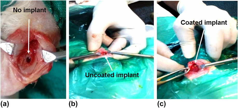
Surgery was carried out under sedation by the injection of xylazine hydrochloride (Injection Xylaxin®, Indian Immunologicals, Ahmedabad, India) at a dose of 1 mg/kg body weight and ketamine hydrochloride (Ketalar®, Parke-Davis, Hyderabad, India) at a dose of 25 mg/kg body weight intramuscularly. A bone defect (2.1 mm dia. × 10.05 mm length) in all the animals was created bilaterally in the distal femur bone with the help of a motorized dental drill [Figs. 1(a)–1(c)]. In all animals, the specimen was implanted along the transverse direction of rabbit femur and implants were held in position by suturing muscle, subcutaneous tissue, and skin in layers. All the animals were administered using injection Cefotaxime sodium (Mapra India, Kolkata, India) at a dose rate of 25 mg/kg body weight intramuscularly, at 12 h interval daily for 5 days and Meloxicam (Melonex®, Intas Pharmaceuticals, Ahmedabad, India) at 0.2 mL once daily for 5 days. Surgical wounds were dressed daily with povidone-iodine and antibiotic ointment for 10 days postoperatively.
Placement of the implants at the defect site in vivo; (a) defect created without implant, (b) implant without coating and (c) implant having tri-layer coating.

2. Postoperative evaluation
Bone regeneration was assessed using sequential radiographs taken immediately after operation and in every month interval up to 3 months. Radiographs were used to assess implant status, bone regeneration, and host-bone reaction. Two investigators independently scored the radiographs in accordance with the blind review process. Histological evaluation was carried out from the bone specimens at 45 and 90 days, first fixed in 10% formalin for 7 days and subsequently were decalcified using Goodling and Stewart’s fluid containing 15 mL formic acid, 5 mL formalin, and 80 mL distilled water, followed by fixation with 4% paraformaldehyde. These samples were embedded in paraffin wax to make sections of 4 μm thickness. Haematoxylin and eosin staining was used to assess host bone’s response to the implant. The histological scoring method was adopted to scrutinize the bone formation. Cellular events were assessed and compared using a scale of 0–4 with ‘0’ indicative of absence, while 1–4 was for mild, moderate, marked, and severe, respectively. From each slide, three sites were examined by an assessor and cross-examination was carried out by a blind observer. The average was calculated from 3 data for each group.
Intramuscular injection of fluorochrome (oxytetracycline dehydrate, Pfizer, Mumbai, India, dosage 25 mg/kg body weight) was given 25 days before the sacrifices at 45 and 90 days to assess new bone formation. A 2-6-2 pattern was followed for the injections. Implant-bone segments, without decalcification, were ground to 20 μm size specimen using graded series of sand papers. The specimens were observed under UV light with Leica DM 2000 Bright light phase contrast and a fluorescence microscope (Leica Microsystems, Weztlar, Germany) including Leica qwain software to determine the amount of newly formed bone. Under this lighting, oxytetracycline labeling made the new bone fluoresce with a golden-yellow color, while old bone had a dark sea green hue. The amount of new bone formation was calculated using ImageJ software (National Institute of Health, Bethesda, Maryland). Using this software, we measured the area that was covered by yellow color. The analysis was performed by taking data from three images of each group.
After sacrificing the rabbits at days 45 and 90, the bone samples were used for interfacial study between bone and implant using scanning electron microscopy (SEM). Samples preparation included fixing in 5% glutaraldehyde in PBS buffer for 48 h followed by gradual ethanol series drying. The dried samples were subjected to gold coating before imaging using a field emission scanning electron microscope (FESEM; SUPRA 40, Carl Zeiss, Jena, Germany).
Implanted bone samples from the euthanized animals were subjected to a mechanical push-out test to study bonding strength at the bone-implant interface at two time points of 45 and 90 days. Soft tissues from bone were first detached and then the bone samples, soaked in physiological saline by gauze, were refrigerated. Before push-out test, the samples were dried in an air oven at 50 °C first and used further. First, the samples were kept on a hardened SS metallic supporting jig having a hole with diameter just larger than implants’ diameter. A suitable plunger having a diameter equal to the sample diameter was pushed against that supporting jig hole after ensuring the axis alignment of plunger using a universal testing machine (Instron 5500R, High Wycombe, United Kingdom) with a constant crosshead speed of 0.5 mm/min till bone-implant interface failure. Considering the cylindrical profile of the implant, the contact area of bone attached was calculated (height × circumference). Finally, the shear stress at failure was calculated by dividing failure load by contact area.
Toxicological effects of coated implants on other tissues were studied by assessing histology of the two vital excretory organs, viz., liver and kidney including another vital organ, heart. The procedures include collection of heart, liver, and kidney from animals after sacrificing at 90 days and preservation in 10% buffered formalin solution. After staining with hematoxylene and eosin solution, sections were examined by using a microscope.
3. Statistical analysis
Unless specified, data have been presented as mean ± standard deviation (SD) with a sample size (n) of 4. An analysis for differences between uncoated and coated samples was performed using one-way ANOVA. Differences were considered significant for P = 0.05(*), 0.01(**), and 0.001(***) for bone formation. The sign “*”indicates the different level of significance. All statistical analyses were conducted in the R statistical environment.
III. RESULTS
A. Phase analysis by XRD and FTIR
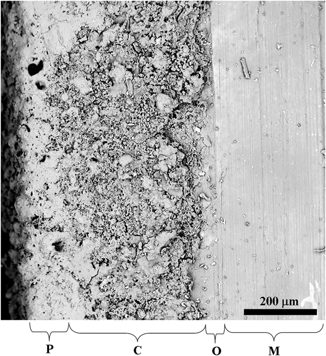
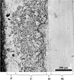
Figure 2 shows a typical interfacial SEM microstructure of the trilayered coated metal sample, where M is the metal surface, O is the oxide layer (with average coating thickness 50–80 µm), C is the ceramic layer (∼350 µm average coating thickness), and P is the chitosan polymer layer (with average coating thickness 50–90 µm).
SEM of the multilayered coated sample’s interface [where M is the metal surface, O is the oxide layer (with average coating thickness 50–80 µm), C is the ceramic layer (∼350 µm average coating thickness), and P is the chitosan polymer layer (with average coating thickness 50–90 µm)].

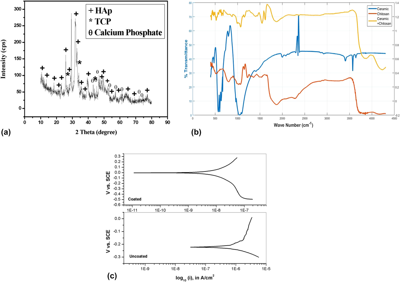
XRD of the top surface, as shown in Fig. 3(a), showed mainly the phase HAp matched with JCPDS PDF no. 74-0566 [maximum peak intensity at 31.85° 2θ with 2.818 Å d-spacing at (211)] together with the phase of TCP (matched with JCPDS PDF no. 01-086-1585) [peak of (222) plane at 28.64° 2θ and d-spacing 2.751 Å] and calcium phosphate hydroxide (matched with JCPDS PDF no. 01-083-1887-1889). Amorphicity in the XRD pattern was also noted due to the layer of polymer chitosan at the outermost layer.
XRD pattern coated implant material (a); FTIR pattern of chitosan, ceramic, and ceramic + chitosan (b); and potentiodynamic curve of the coated and uncoated 316L SS implant material (c).

FTIR spectra of the powders are given in Fig. 3(b), where spectra of pure HAp and chitosan were also shown for comparison purpose only. Functional groups observed at 1046 cm−1 [for C–O acetamide (νC–O)], 1120 and 1178 cm−1 (for –C–O–C), 1261 cm−1 (for C–O), and 1560 cm−1 [for –NH2 bending vibration in amino group (δNH)] confirmed the presence of chitosan. Moreover, the mode of –C=O in the acetamide group (amide I bond) (at 1876 cm−1) and –CH2 stretching vibration of pyranose ring (νC–H) were observed at 2889 cm−1. Functional groups were observed at 498, 565, 597, 1005, and 1046 cm−1 (for PO43−). 639 cm−1 (for O–H bending mode), and 1212 and 1261 cm−1 (for P–O–H plane of HPO42−, respectively) indicates the phase HAp which is also compared with the reference peak as given in Fig. 3(b). Hydrated O–H peaks were also present at 3486 cm−1 and 3543 cm−1, respectively.
B. Corrosion study
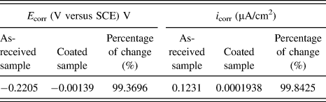
The corrosion rate (i corr) of coated and uncoated samples was determined by the electrochemical polarization technique. Figure 3(c) shows the polarization curve of the coated and uncoated samples. Table I indicates that the E corr value of the coated sample was 99.4% more positive than the uncoated one, and the i corr value of the coated sample was 99.8% lower than that of the uncoated one. Zero or almost no corrosion propagation is only possible when the value of E corr is in near zero or in positive side and i corr is also in near zero or very small. In the present study thus, the corrosion prevention capability of the coated implant is much better (>99%) than that of the bare implant.
E corr and i corr of as-uncoated and coated samples of SS 316L.

C. Radiological observation
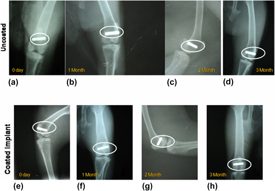
Figures 4(a)–4(h) exhibit the sequential radiographs of the rabbit distal femur implanted with both uncoated [Figs. 4(a)–4(d)] and coated [Figs. 4(e)–4(h)] SS implants. At ‘0’ day, the bone defect treated with the uncoated implant in the distal epiphysis of rabbit femur showed contact of the implant in cis and trans cortex of the defect. The same bone at 1 month showed the presence of the intact implant without any alteration of shape, size, position, and radiodensity. At 2 months, the postoperative repairing radiograph showed the presence of the hyperdense implant without any appreciable alteration of the implant as well as the defect. The radiograph also evidenced no perceptible radiographic changes in the adjacent hard tissue. The final radiograph at 3 months showed unaltered implant radiographically in its density, shape, and size. The defect evidenced shrinkage in its size and bridging the cortex in the epiphyseal area.
X-ray radiography images of the uncoated sample after (a) 0 month, (b) 1 month, (c) 2 months, and (d) 3 months; X-ray images of the coated sample after (e) 0 month, (f) 1 month, (g) 2 months, and (h) 3 months.

The coated implants at ‘0’ day immediately after implantation showed the presence of the cylindrical hyperdense implant occupying in the distal epiphyses of femur bone. Subsequently at 1 month, the radiograph showed the presence of the unaltered hyperdense implant but there was a periosteal reaction adjacent to the implant. At 2 months, the skiagram showed intact implant without alteration of shape, size, and density, but adjacent bony tissue evidenced remodeling in the form of resorption of callus in the medullary cavity as a cortical line. At 3 months, the bone was completely remodeled with the presence of the reformed cortical line in the cortical defect area and presence of bony tissue which was similar density of adjacent healthy bone indicating complete remodeling.
D. Histology
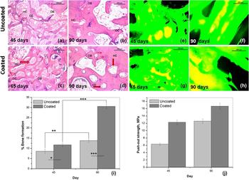
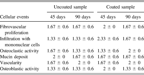
Figures 5(a)–5(d) and Table II show histological images of uncoated [Figs. 5(a) and 5(b)] and coated [Figs. 5(c) and 5(d)] implanted bones at two time points of 45 and 90 days and their semiquantitative cellular events statistically represented in tabular form, respectively.
Histological images of bone tissues surrounding the uncoated sample after (a) 45 days and (b) 90 days; coated sample after (c) 45 days and (d) 90 days (HC: Haversian canal, OB: Osteoblasts, OC: Osteoclasts); fluorochrome labeling images of uncoated samples after (e) 45 days and (f) 90 days, coated samples after (g) 45 days and (h) 90 days (golden-yellow fluorescence is for new bone and sea green is for old bone); (i) percentage of bone formation of both samples at two time points {(where significance * = 0.05, ** = 0.01, *** = 0.001), * indicating different levels of significance} and (j) push-out test values at two time points (45 and 90 days).

Mean with SD of the score sheet for different cellular events at days 45 and 90 after observing the histological images of coated and uncoated samples.

The score sheet value is considered as (0) absent, (1) mild, (2) moderate, (3) marked, and (4) severe.
The section of the uncoated sample at day 45 depicted bony architecture characterized by the formation of bony spicules and plates. The intervening osteons were rich in collagen, mucin, and connective tissue. Mononuclear cell infiltration was more in the peripheral region of osteon. The vascularity of the parenchyma was moderate, and medullary portion showed clusters of fat cells, mononuclear cells, R.B.C., and mucinious deposits. The osteoblast in bony spicules was marked and the formation of cancellous bone was prominent in the trabecular bony structure. The section at 90 days from the same group depicted a well-formed bony structure with haversian system, bony spicules, and osteons in the medullary portion of osteoid. The osteoblasts were numerous in the cortical portion of bone and osteoclast remained in the margin of medullary cavity. Mucinious structure, collagen, and cancellous bony lamellae were seen around the margin of periosteum. Well vascularity of the total structure was observed particularly in the cortical portion along with angiogenesis in periphery of bony plates.
The microsection at day 45 of the coated sample depicted well-organised bony parenchyma characterised by the formation of numerous haversian canals and bony trabeculae. The haversian canal was filled with large number of mononuclear cells and osteocytes. Angiogenesis was quite marked around the periphery of the bony trabeculae. Fibrous tissue proliferation was seen in periosteum and inner aspect of the trabecular bony lamellae. After 90 days, the histological section of the same group depicted a well-organised bony plate consisting of osteons, haversian system, and trabecular portion of bony parenchyma. Osteoblast and osteoclast proliferation were found in the periphery of the cortex and inner aspect of medullary lining. Angiogenesis was marked around the haversian canal, and peripheral portion of the bony plates.
E. Fluorochrome labeling study results
Figures 5(e)–5(i) show fluorochrome labeling images including graphical representation to find the new bone formation in both uncoated [Figs. 5(e) and 5(f)] and coated [Figs. 5(g) and 5(h)] samples after 45 days and 90 days and the percentage of bone formation, respectively. The images with oxytetracycline labeling imparted golden-yellow fluorescence depicting new bone formation and sea green appearances indicate old bone. Similarly, microphotographs of the uncoated sample section at 45 days showed double tone golden-yellow fluorescence in a constricted region (8.4 ± 1.1%) and the majority of host bones demonstrated dark sea green homogenous color; in the coated sample at 45 days, bone formation was slightly better than the uncoated sample (11.7 ± 0.8%) as bone formation was restricted centrally. Scattered regions of golden-yellow fluorescence (nearly 30.6 ± 1.0%) were seen in the coated implant at 90 days while this was slightly better new bone formation (13.8 ± 0.8%) for uncoated sample after same time.
F. Push-out test
Push-out strength of the implanted samples were measured at days 45 and 90 after harvesting bone samples to assess the bonding strength of the implant and this has been graphically represented in Fig. 5(j). Push-out strength of uncoated and coated samples after 45 days were 6.31 MPa and 12.26 MPa, respectively, while after 90 days, these were 12.58 MPa and 16.67 MPa, respectively.
G. Toxicological study of vital organs
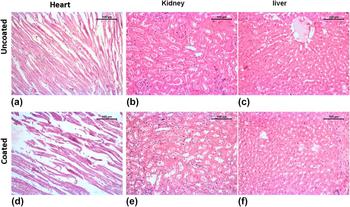
Figure 6 represents histology of liver, heart, and kidney at 90 days postoperatively. For uncoated implants, histology of heart showed almost normal architectural pattern consisting of branching muscle, slight congestion, and mild infiltration with mononuclear cells. No heart failure cells were found. The histological section of kidney showed tubular and glomerular structure almost within normal range. In between few tubules, there was an accumulation of eosinophilic exudates with mild mononuclear cell proliferation. The interstitial tissue retained normal structure and some renal casts were formed inside the few tubules. The liver microstructure showed a normal architectural pattern with mild necrosis of hepatic cells around the margin of central vein. The central vein was filled with edematous exudates and other hepatic structures retained their normalcy. In the coated sample, the histological section of heart depicted almost normal architecture. Some places showed mild mucinious deposits and accumulation of R.B.C. in between muscle fiber. Focal necrosis of cardiac muscles was very rare rather retaining normal structure. The medullary portion of the tubule of kidney exhibited normal tubular arrangement with moderate dilatation of renal spaces. The vascularity of this portion was normal. The architecture of liver depicted almost healthy liver parenchyma characterized by well-organized hepatic tissues and cord, mononuclear cell, and von Kupffer cell. The vascularity of the total structure was in normal range.
Histological images of the uncoated sample (a) heart, (b) kidney, and (c) liver and coated sample (d) heart, (e) kidney, and (f) liver at 90 days.

H. Microstructural analysis on in vivo samples
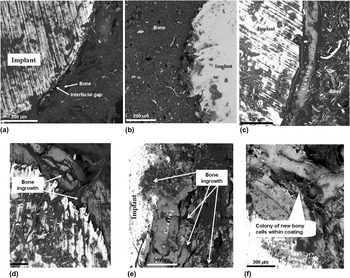
SEM was carried out to study the osseous in-growth process across the interfacial regions and Fig. 7(a)–7(f) show the SEM photomicrographs of the bone-implant interface at ‘45’ and ‘90’ days. The metal and bone interface is quite clear in all uncoated samples [Figs. 7(a) and 7(b)]. Initiation of bony tissue proliferation took place at 45 days in the uncoated sample and interfacial gap between bone and implant was decreased, whereas the amount of new bone growth is higher in 90-day samples and good bonding with the implant material. Figures 7(c) and 7(d) show initiation of bone regeneration toward the coated implant and presence of osseous tissue at pores of coating at the initial stage and reduced interfacial gap between bone and implant at 90 days. After 90 days, proliferation of new bone tissue around in the coated implant was much higher than 45 days [Figs. 7(e) and 7(f)].
SEM images of bone-implant interface (in vivo) of the uncoated sample taken after (a) 45 days (X 390) and (b) 90 days (X 360); coated sample taken after 45 days in different magnifications revealing (c) trilayered coating and tissues (X 390) and (d) initiation of bone regeneration between pores (X 460); coated sample taken after 90 days at (e) X 260 and (f) revealing tissue colony formation between pores of coating (X 260).

IV. DISCUSSION
Bone implants are routinely used for fracture fixation, correction and stabilization of spinal fractures, arthrodesis, and maxillofacial applications. The principal goal behind this is to offer better mechanical stabilization to get best possible outcome during physiologic loading of bones. Several probable factors including systemic factors, local factors, and surgical factors may compromise to attain the desired goal.Reference Bishop, Palanca, Bellino and Lowenberg21 These drawbacks led the researchers to find out an optimal strategy to achieve more robust bone healing. In the present investigation, efforts have been made for the first time to detail the efficacy of trilayered coating consisting of passivated metal implants with bilayered HAp and chitosan coating (Fig. 2). EPD of the ceramic phase gave microporous layer without having interfacial gap on the passivated layer. This is favourable for cell/tissue in-growth in the ceramic layer with better bone bonding ability subsequently. XRD of the top surface confirmed primarily the HAp phase with other calcium phosphate phases and amorphous content mainly due to the presence of chitosan at the outermost layer. FTIR confirmed the phases thus observed, presence of chitosan, and composite nature when combined with ceramic. Respective bands for functional groups (hydroxyl, phosphates, acetamide, C–O, and –NH2) confirmed that both ceramic and polymer combined very effectively and they were apposed as observed in Fig. 2. The outermost layer, directly interacts with the living tissue first, helped in biocompatibility between implant and surrounding tissue and eventually reduced the possibility of implant rejection. The inner ceramic layer triggers initiation of osteoblast proliferation, continuity of cell formation and serves as a protective barrier between metal implant and corrosive body fluid, reducing the corrosion rate of the implant.
The potentiodynamic anodic polarization scan is dynamic and continuous. It represents the behavior profile of the sample when scanned in cathodic to anodic direction. Lower current density indicates slower propagation of the corrosion process, which is inversely proportional to the implant life. The corrosion rate is inversely proportional to the E corr value and the current density is proportional to the corrosion rate. Generally, the increase in E corr value and decrease in i corr value indicate higher corrosion resistance of the corresponding sample, which can be seen for the coated sample. Furthermore, the innermost layer was oxide (passivated) layer; in the long run, when bioceramic coating dissolves in body fluid, this layer may protect the implant from corrosion and control carcinogenic ion discharge of the metallic implant.Reference Chew, Zein and Ahmad22,Reference Kamachimudali, Sridhar and Raj23 It was shown by Kim and Young that the passivated layer restricted the corrosion rate in high chloride environment.Reference Kim and Young24 Since body fluid contains corrosive Na+ and Cl−,Reference Kamachimudali, Sridhar and Raj23 the presence of passive layer is crucial in restricting the corrosion rate. The bioceramic coating was better in corrosion prevention as well as stimulating activity of osteoblast cells as observed through estimation of E corr and i corr. Values of i corr and E corr were drastically changed so the corrosion rate was also reduced. The value of i corr of the coated implant was so small that almost no corrosion took place. Due to the double layer protection of the passivated oxide layer and bioceramic coating on 316L SS, the rate of corrosion is improved up to 99% indicating reduced corrosion rate of the implant.Reference Bosco, Van Den Beucken, Leeuwenburgh and Jansen25,Reference Thamaraiselvi and Rajeswari26 Similar reduction in the corrosion rate was also reported for passivation in borate solution at 0.909 V for 60 min followed by HAp coating (20 mA for 30 min).Reference Dhar and Mitra27,Reference Dhar, Mitra and Duari28 The XRD pattern mainly indicated HAp with negligible other calcium phosphate hydroxide. FTIR results complimented the XRD and proved the retention of both ceramic and polymer (chitosan) phases in the final coated implants.
For investigating host bone and implant interactions, in vivo trials were conducted by using the rabbit distal femur model. Implants were press-fitted at the defect site and without marked inflammatory reaction, which indicates the well-acceptance of the implant in the bony defect. Radiology is an ideal noninvasive method for studying host bone-implant interface, at different time points postimplantation.Reference Arinzeh, Peter, Archambault, Van Den Bos, Gordon, Kraus, Smith and Kadiyala29 A sequential reduction of the radiodensity with time is an indication of synthesis of mineralized callus leading to the bone healing. Also, the diameter of the coated implant reduced gradually, indicating the initiation of in-growths of newly formed bony tissue toward the implant and more attachment with the host bone. Fluorochrome labeling study is a significant tool to quantify bone mineralization.Reference van Gaalen, Kruyt, Geuze, de Bruijn, Alblas and Dhert30 After injection at a specific time, fluorochrome (oxytetracycline) will directly bind to the newly calcified areas at the defect site, as tetracycline can effectively demarcate new bone formation during bone mineralization and remodeling processes.Reference Kovar, Xu, Draney, Cupp, Simpson and Olive31 Tetracycline generally pursues ionized calcium and gets deposited in undergoing mineralization tissue.Reference Dahners and Bos32,Reference Gibson, Thornton and Brown33 Under fluorescence microscopy in UV light, new bone emits golden-yellow fluorescence and sea green by the host bone. In this study, the increased area of new bone formation from peri-implant tissue in the trilayered coated implant was observed at 90 days, indicating the proliferation of host osteoblasts toward chitosan and HAp coating compared to moderate new bone formation in the uncoated implant. Higher new bone formation in the coated sample may be due to the presence of chitosan in the HAp matrix.
To understand the cellular events during bone regeneration, histology from the peri-implant bone tissue has been carried out. Histology of the coated sample showed higher osteoblast cell generation than the uncoated sample. New cells were due to regrowth surrounding coated and uncoated samples. However, cells increased with time in both cases. As per the semiquantitative report of histology scoring (Table II), the coated samples showed better result in fibrovascular proliferation, infiltration with mononuclear cells, osteoclastic activity, and vascularity after 90 days. The osteoblastic activity was initially high in the coated sample but with time, the activity was saturated. In a similar finding of chitosan film-coated titanium substrate, enhanced osteoblast proliferation, alkaline phosphatase activity,Reference Shi, Neoh, Kang, Poh and Wang34 and osteogenic properties were observed.Reference Di Martino, Sittinger and Risbud35,Reference Ohara, Hayashi, Yamada, Kim, Matsunaga, Yanagiguchi and Ikeda36 Though it is not an accurate quantitative representation, the results strongly signify that the bone biological response to chitosan/HAp coatings is more than uncoated SS materials and the score sheets provide us an indication of bone regeneration based on different cellular events.
Push-out test is considered to be a parameter to assess healing capabilities within the bone-implant interfaceReference Brunski, Puleo and Nanci37,Reference Kempen, Lu, Heijink, Hefferan, Creemers, Maran, Yaszemski and Dhert38 and to assess the active changes of osseointegration than any single structural parameter.Reference Johansson, Han, Wennerberg and Albrektsson39 In this study, higher interfacial strength of the coated sample than uncoated implanted samples endorsed excellent tissue in-growth at the host-bone implant interface after 90 days postoperatively as evidenced from push-out test data, which is also an indirect indication of healing capabilities within the bone-implant interfaceReference Brunski, Puleo and Nanci37,Reference Kempen, Lu, Heijink, Hefferan, Creemers, Maran, Yaszemski and Dhert38 and active changes of osseointegration.Reference Johansson, Han, Wennerberg and Albrektsson39 Although both chitosan and HAp are biocompatible when implanted in body, any toxicity involving the implant was ruled out histologically with two major excretory organs—liver and kidney—and other one vital organ, i.e., heart if there is any biodistribution of the degraded coated material products. The histology images did not apparently reveal any abnormality of organs thus guardedly concluding no adverse toxicity to the body. The microstructural study (by SEM) also demonstrated higher osseointegration capability of the trilayered coated 316L SS implant as compared to control as the interfacial gap between host bone and implant was almost negligible at 90 days postoperatively, indicating the proliferation of more amount of osseous tissue toward the implant. A similar finding of tightening of the pure chitosan rod was observed when coating the implant layer-by-layer.Reference Wang and Hu40
This study demonstrates the application of the trilayered coated 316L SS implant as in vivo proof of concept for bone defect repair. The coated 316L SS implant is superior in terms of their structure, composition, and biomechanical property, which supports a cost-effective one-step operative process reducing time consumption and cell-based multiple surgical technique.
V. CONCLUSION
Trilayered coated 316L SS implants with ceramic layer (composed of mainly HAp phase and other calcium phosphates) sandwiched between passivated oxide layer on the metal substrate and chitosan layer at the periphery have been developed and characterized up to preclinical trial. Formed phases and microstructures have been analyzed by XRD, FTIR, and SEM. The trilayered coating showed excellent corrosion resistance as evidenced from the electrochemical corrosion study (corrosion prevention capability of the coated implant is >99% better than that of the bare implant). Through the detailed in vivo characterization, it has been established that the coating composition helped bone-cell formation and growth of newly formed osseous tissue around the coated implant with time, as depicted by SEM images as well as the results of histology and fluorochrome labeling studies. Push-out strength data of the coated sample were 50% higher than uncoated samples at 45 days and 27% higher in 90 days due to stronger attachment of new bone cells with the implant. Our findings, thus, vouch for the potential of this implant in orthopedic fracture fixation and enhanced osseointegration and mechanical stability.
ACKNOWLEDGMENTS
The authors would like to thank Technical Education Quality Improvement Program Phase II (TEQIP-II) for financial support. The authors would also like to thank the Director, CSIR-Central Glass and Ceramic Research Institute, Kolkata, India, and Vice Chancellor, West Bengal University of Animal and Fishery Sciences, Kolkata, India, for their generous and kind support to this work. Dr. Howa Begam (School of Bioscience and Engineering, Jadavpur University, Kolkata, India) and all the personnel involved for characterization of materials are sincerely acknowledged.