I. INTRODUCTION
Increasing concerns in public opinion about the environment and progressively strict legislation are the driving forces for a gradual, yet consistent pressure for substituting currently used polymers with other materials, perceived as more environmentally benign. Polylactide (PLA) is a linear aliphatic thermoplastic polyester, generally produced by the ring-opening polymerization of the lactide monomer.Reference Sinha Ray and Okamoto1 Lactide is a cyclic dimer prepared by the controlled depolymerization of lactic acid, which in turn is obtained by the fermentation of corn, sugar cane, sugar beet, etc.Reference Sinha Ray and Okamoto1
The annual production of PLA worldwide is increasing not only for the environmental concerns, but also because it can be prepared from renewable resources, helping to preserve the petroleum reserves. It is readily fabricated, thus is a promising material suitable to replace commodity polymers in many end-use applications.Reference Sinha Ray, Ramontjia and Yu2 However, PLA is a slowly crystallizing material, so it has a poor processability under normal conditions. Also in its amorphous form, the range of application of PLA is severely limited by its low glass transition temperature (T g). Hence, there is a need to improve its mechanical properties, especially of the crystallized material to appropriately substitute traditional thermoplastic polymers. To improve the mechanical properties of PLA, a wealth of investigations have been carried out over the last few years, reinforcing it with different types of fillers and nanofillers.Reference Sinha Ray, Ramontjia and Yu2
Fiber-filled composites are common in the academia and in the industry. However, the diameter of the normally used fibrous fillers usually exceeds tens of micrometers, therefore producing microcomposites, when dispersed in a polymeric matrix.
A number of reports appeared in the literature in which PLA was reinforced with natural fibers, such as flax,Reference Oksman, Skrifvars and Selin3 kenaf fibers,Reference Graupner, Herrmann and Müssig4 cotton,Reference Graupner, Herrmann and Müssig4 hemp,Reference Graupner, Herrmann and Müssig4 wood fibers,Reference Huda, Drzal, Misra and Mohanty5, Reference Meng, Hetzer and De Kee6 and mixtures thereof.Reference Graupner, Herrmann and Müssig4 Artificial fibers, such as Lyocell, were also used as fillers.Reference Graupner, Herrmann and Müssig4
The rationale at the basis of the nanocomposite concept is that a decrease in the size of the filler brings about a large increase in interfacial area. This in turn largely changes the macroscopic properties of the material. Some applications of this approach to fiber-reinforced nanocomposites were recently reported.Reference Wang, Chen, Xiong, Pang and Xiong7–Reference Swart, Olsson, Hedenqvist and Mallon15
Xiong and coworkers obtained the in situ formation of submicrometric poly(glycolic acid) fibrils within a PLA-co-poly(caprolactone) matrix, improving the shape-memory properties of the composite obtained therefrom.Reference Wang, Chen, Xiong, Pang and Xiong7
Yano and colleagues filled PLA with quantities up to 10% of fibrillated cellulose with submicrometric diameter, observing increases in tensile modulus and strength.Reference Suryanegara, Nakagaito and Yano8
Carbon nanotubes (CNTs) are another example of suitable fibrous material for the preparation of nanocomposites, which, however, pose several problems in filler dispersion due to their tendency to bundle and aggregate.Reference Rizvi, Khan and Naguib9, Reference Wu, Wu, Zhou, Zhang and Yang10
By electrospinning, fibers with a nanometric diameter can be produced; thus, this is an ideal method for the production of nanosized fibrous fillers to be included in a polymer matrix, allowing to produce nanocomposites. However, electrospun nanofibers are mostly proposed for applications in fields such as nanocatalysis, tissue scaffolds, protective clothing, filtration, and optical electronics. After the pioneering work of Kim and RenekerReference Kim and Reneker16 and Bergshoef and Vancso,Reference Bergshoef and Vancso17 very few works were published on the use of electrospun fibers as fillers in polymer-based composites.Reference Zucchelli, Focarete, Gualandi and Ramakrishna12–Reference Swart, Olsson, Hedenqvist and Mallon15, Reference Bayley, Hedenqvist and Mallon18, Reference Matabola, de Vries, Luyt and Kumar19
Nylon fibers have been extensively used as reinforcement of several polymer matrices, and recent literature reports showed the potential in property improvement of electrospun nylon fibers especially in poly (methyl methacrylate),Reference Chen, Huang, Dong, He, Liu, Hu and Li20 polycaprolactone (PCL),Reference Neppalli, Marega, Marigo, Bajgai, Kim and Causin13, Reference Neppalli, Marega, Marigo, Bajgai, Kim and Causin14 and dental resins.Reference Fong21, Reference Tian, Gao, Liu, Liao, Xu, Hedin and Fong22 In our previous work, PCL composites filled with electrospun nylon 6 (N6) fibers were prepared by a melt processing technique.Reference Neppalli, Marega, Marigo, Bajgai, Kim and Causin13, Reference Neppalli, Marega, Marigo, Bajgai, Kim and Causin14 With a very low filler content (3%), a simultaneous increase in strength, stiffness, and ductility was observed, which is unusual in nanocomposites containing other types of fillers, where the increase in modulus normally happens at the expense of elongation at break.Reference Neppalli, Marega, Marigo, Bajgai, Kim and Causin13 Such potential was corroborated also by other authors. Recently, Mallon and coworkers reported that electrospun fibers of polyacrylonitrile-graft-poly(dimethyl siloxane) were able to confer to a cross-linked poly(dimethyl siloxane) matrix not only strength and stiffness, but also a remarkable extensibility.Reference Bayley, Hedenqvist and Mallon18 Moreover, it was reported that electrospun fibers could modify the degradation rate of PCL.Reference Neppalli, Marega, Marigo, Bajgai, Kim and Causin14
According to the authors’ knowledge, PLA was never reinforced with any kind of electrospun fibers. In this work, we filled PLA with electrospun N6 fibers to study the effect of fibers on the structure, morphology, mechanical properties, and degradation behavior.
II. EXPERIMENTAL
PLA with D content of 1.1–1.7% was obtained from Unitika Co. Ltd. (Osaka, Japan). According to the supplier, it had a weight average molecular weight M w = 200 kg/mol, density = 1.25 g/cm3 (ASTM 1238).
Electrospun N6 fibers were used as fillers. Electrospinning was carried out on a 22 wt% (viscosity, 1320 cps) N6 solution in formic acid/acetic acid (80/20, wt/wt) with an applied voltage of 22 kV and tip-to-collector distance of 12 cm. All fibers were dried prior to use in vacuum oven at 100 °C to remove adsorbed moisture and residual solvent. The characterization of the electrospun mat was done after this drying stage.
Two types of composites with different amounts of filler content were prepared as in our previous work.Reference Neppalli, Marega, Marigo, Bajgai, Kim and Causin13, Reference Neppalli, Marega, Marigo, Bajgai, Kim and Causin14 The first composite, i.e., PLANY1.5, was prepared by keeping the N6 fiber mat between two compression-molded PLA sheets and applying pressure and heat in a press (Alfredo Carrea, Genova, Italy) at 180 °C. PLA was melted and percolated between the voids in the mat, constituting a continuous phase in which the fibers were dispersed. The second composite, PLANY2.5, was prepared by keeping two N6 fiber mats alternated by PLA films. Table I shows the sample codes and the wt% of filler content in the composites. All the prepared samples were annealed in an oven at 100 °C for 4 h because they were amorphous [confirmed by wide-angle x-ray diffraction (WAXD) and differential scanning calorimetry (DSC)] right after treatment in the press.
Formulation and codes of the samples.

PLA, poly(lactide).
A. Wide-angle x-ray diffraction
WAXD transmission patterns were recorded in the diffraction angular range 5–40° 2θ by a diffractometer GD 2000 (Ital Structures, Riva del Garda, Italy). The instrument works in a Seeman–Bohlin geometry, with a quartz crystal monochromator on the primary beam (CuKα1 radiation). The application of the least-squares fit procedure elaborated by Hindeleh and JohnsonReference Hindeleh and Johnson23 gave the degree of crystallinity by weight which was then transformed in degree of crystallinity by volumeReference Vonk, Glatter and Kratky24 (φ WAXD).
B. Small-angle x-ray scattering
The small-angle x-ray scattering (SAXS) patterns of the samples were recorded by a MBraun system (Graz, Austria), using a CuKα radiation from a Philips PW 1830 x-ray generator (Almelo, Netherlands). The data were collected by a position sensitive detector and were successively corrected for blank scattering, desmeared, and Lorentz-corrected. A fitting method of SAXS patterns was developed on the basis of a theoretical modelReference Blundell25–Reference Marega, Causin and Marigo28 referring to the Hosemann modelReference Hosemann and Bagchi29 that assumes the presence of lamellar stacks having an infinite side dimension. This assumption takes into account a monodimensional electron density change along the normal direction to the lamellae.
The intensity profile was evaluated as:

where
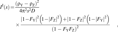
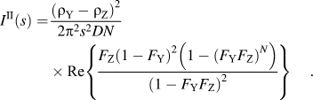
In these equations, F Y and F Z represent the Fourier transforms of the distribution functions of the lamellae (Y) and of the amorphous regions interposed between the lamellae (Z), ρ Y and ρ Z are the electron densities of the crystalline and amorphous regions, respectively. N is the number of lamellae in the lamellar stacks and X the average long period.
C. Differential scanning calorimetry
All the measurements were carried out with a TA Instruments model 2920 calorimeter (New Castle, DE) operating under N2 atmosphere. Samples weighing ∼5 mg closed in aluminum pans were used throughout the experiments. Indium and tin of high purity were used for calibrating the DSC temperature and enthalpy scales. The kinetics of crystallization was studied by subjecting each sample to the following thermal cycle: after erasure of previous thermal history by keeping the polymer at 200 °C for 5 min, it was cooled at the maximum rate to the crystallization temperature (T c). The heat evolved during the transition was monitored as a function of time during an isothermal at T c of suitable length. The fraction X of material crystallized after the time t was estimated from the relation:
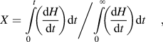
where the numerator is the heat generated at time t and the denominator is the total heat of crystallization. The Avrami equationReference Avrami30 was used to correlate X with time:

K is the kinetic constant of crystallization, n is a coefficient linked to the time dependence and the dimensions of growth of crystallites.
This equation is linearized in the following way:

Plotting ln[−ln(1 − X)] versus ln(t − t 0) and fitting with a straight line, n and K can be obtained by the slope and the intercept of the obtained line.
D. Polarized light optical microscopy
The crystallization behavior of the samples was studied with a Leica DM400M polarized light microscope (Weitzlar, Germany). The samples were placed between a glass slide and a cover slip and were kept at 180 °C for 10 min to ensure uniform melting and to delete their thermal history. The slide was then transferred to a Mettler FP82HT hot stage set (Greifensee, Switzerland) at 100 °C. The photomicrographs were taken between cross-polarizers with a Leica DFC280 digital camera. To suitably compare the behavior of different samples, photomicrographs were taken for all samples after 20 min of isothermal crystallization.
E. Scanning electron microscopy
Scanning electron microscopy (SEM) pictures were obtained by a XL30 scanning electron microscope (Philips). All considered specimens were gold coated. Samples were freezed in liquid nitrogen for 5 min, rapidly retrieved, and broken.
F. Infrared spectroscopy
Infrared (IR) absorption spectra were acquired on a FTIR Nicolet 5700 spectrometer (Madison, WI) equipped with a germanium-attenuated total reflectance accessory Thermo Smart Performer. The spectral region spanned from 4000 to 600 cm−1, with a resolution of 4 cm−1. Two hundred and fifty-six acquisitions were gathered. A cross section of the materials was sampled to detect the signals of both electrospun fibers and matrix.
G. Degradation studies
Degradation studies of the samples were performed in two different media. First, the materials were exposed to phosphate buffer solution (PBS) at pH 7.4 for 4 months. Since in this medium no significant degradation was observed, the samples were moved into a NaOH (0.1 M) solution. All degradation tests were carried out at 65 °C. Samples were taken out from the media at regular time intervals, washed thoroughly with distilled water and dried at room temperature for 24 h, weighed, and returned to the media. Two specimens for each sample were tested in parallel to check the reproducibility of the procedure.
H. Tensile properties
Tensile mechanical properties of rectangular-shaped samples (30 × 10 × 0.5 mm3) were measured using an Instron model 3345 mechanical tester (Norwood, MA) at room temperature and 50% humidity. The strain rate was 5 mm min−1. At least five measurements were performed for each sample.
III. RESULTS AND DISCUSSION
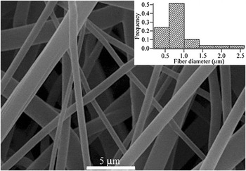
Figure 1 shows a SEM micrograph of the electrospun N6 fibers used in this work. The average diameter of these electrospun fibers was evaluated by performing image analysis on several micrographs, for a total of about 100 fibers, and was found to be 800 nm. Figure 1 also shows in an inset the size distribution for the diameters of the fibers. These diameters are about one order of magnitude smaller (i.e., their specific surface areas are more than 10 times larger) than ordinarily spun fibers. A notable feature is the quite broad distribution of fiber size, with thin fibers coexisting with very large fibers, up to 3 μm in diameter. The quality of the fibers was good, with a smooth surface and no trace of beads.
Scanning electron microscopy (SEM) image of the nylon fiber mat. The inset shows the distribution of fiber diameters.

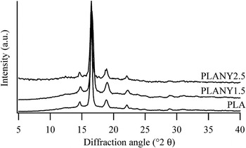
As better detailed in the experimental section and in previous articles,Reference Neppalli, Marega, Marigo, Bajgai, Kim and Causin13, Reference Neppalli, Marega, Marigo, Bajgai, Kim and Causin14 inclusion of the fibers in a continuous PLA matrix was done by percolating, in a compression molding press, molten PLA within the interstices of the fibrous mat. The electrospun fiber mat included in the matrix was nonwoven. The preparation of the composites was done at 180 °C, which is a temperature high enough to melt PLA (T m = 150 °C) but much lower than the melting point of the N6 fibers (T m > 210 °C). It was therefore possible to preserve the network of the electrospun fibers while creating a homogeneous PLA polymeric matrix. The effect of fibers on the structure and morphology of the composites was studied by WAXD. Figure 2 shows the WAXD diffractograms of PLA and its composites PLANY1.5 and PLANY2.5. In all compositions, a major crystalline peak at 2θ ∼ 16.6°, related to the α-phase (110) plane, was observed without the appearance of any crystalline peaks related to N6. Table II shows the degree of crystallinity evaluated by WAXD (φ WAXD) of concerned samples. A small increase in the φ WAXD was observed in the composites, but fibers are not showing much effect on ϕ WAXD.
Wide-angle x-ray diffraction patterns of poly(lactide) (PLA) and its composites with different amounts of filler content.

Degree of crystallinity obtained by wide-angle x-ray diffraction (φ WAXD) and morphological parameters of the lamellar stacks obtained by small-angle x-ray scattering (SAXS) analysis of considered samples.

C is the thickness of the crystalline; A is the thickness of the amorphous layer; D is the long period; and φ SAXS, the crystallinity. σ C/C, σA/A, σ D/D, and σφ/φ SAXS are the distributions of the aforementioned parameters, respectively, and can be interpreted as the relative deviation from the average of the values of such features.
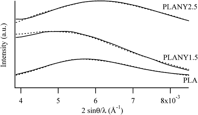
The lamellar morphology of all prepared samples was studied using SAXS. Figure 3 shows the experimental traces due to the matrix and the samples with electrospun fibers. The experimental traces due to the matrix and the samples with electrospun fibers were fitted according to a methodReference Blundell25, Reference Marega, Marigo, Cingano, Zannetti and Paganetto26, Reference Hosemann and Bagchi29 that was shownReference Marega, Causin and Marigo28 to reliably determine the thicknesses and distributions of the crystalline and amorphous layers, the long period and the crystallinity, along with their distribution, associated to lamellar stacks. The fitted traces are shown in Fig. 3, and the morphological features obtained by this procedure are summarized in Table II.
Small-angle x-ray scattering patterns (solid line) of the considered samples; traces calculated during the fitting procedure (dotted line) are also shown.
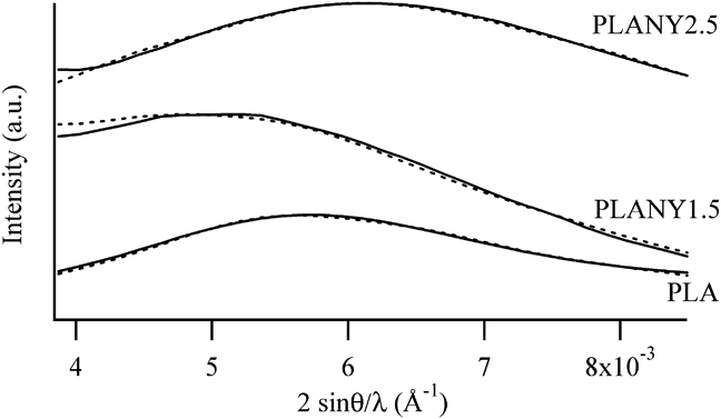
The long period of the SAXS peak of the composite with the lowest filler content, i.e., PLANY1.5, was larger than that of the matrix, whereas when the amount of fibers increased, the SAXS peak shifted toward wider angles. In all composites, the thickness of the lamellae was increased with respect to the neat matrix, although the maximum thickness was achieved in sample PLANY1.5. The thickness of lamellae slightly decreased in PLANY2.5, with respect to sample PLANY1.5. Interestingly, also the thickness of the amorphous layer decreased from PLANY1.5 to PLANY2.5, so the overall effect was that the crystallinity associated to the lamellar stacks of the composites was constant irrespective of the fiber content. It is noteworthy that φ SAXS was significantly higher in the composites than in the neat matrix. The increase in crystallinity noted by WAXD is confirmed by SAXS, but the effect is magnified when the focus is posed on the characterization of the lamellar morphology. It has already been highlighted that the nanofiller often negligibly influences the structure at a crystalline cell level, but it has its most significant effects on polymer lamellae.Reference Lincoln, Vaia, Wang, Hsiao and Krishnamoorti31–Reference Causin, Yang, Marega, Goh and Marigo35
This apparently conflicting behavior, i.e., that the presence of fibers increases the lamellar thickness, which on the other hand starts to decrease beyond a certain filler content, can be explained in analogy to other systems, such as composites filled by montmorilloniteReference Causin, Marega, Saini, Marigo and Ferrara36–Reference Maiti, Nam, Okamoto, Hasegawa and Usuki39 or graphiteReference Causin, Marega, Marigo, Ferrara and Ferraro40 or CNTs.Reference Wu, Wu, Zhou, Zhang and Yang10 Fibers have a double role in influencing the semicrystalline framework of the polymeric matrix. The presence of fibers has on one hand a nucleation effect, bringing about an increase of crystallization degree.Reference Wu, Wu, Zhou, Zhang and Yang10, Reference Neppalli, Marega, Marigo, Bajgai, Kim and Causin13, Reference Neppalli, Marega, Marigo, Bajgai, Kim and Causin14 This was confirmed by DSC, as will be discussed in detail later in this section. On the other hand, as previously observed for other nanofillers, for example CNTs or electrospun fibers, increasing the filler content, and therefore its surface area, some hindering effects on the free motion of macromolecular chains appear, leading to difficulties in attaining thick lamellae, as observed also in this work.Reference Wu, Wu, Zhou, Zhang and Yang10, Reference Neppalli, Marega, Marigo, Bajgai, Kim and Causin13, Reference Causin, Yang, Marega, Goh and Marigo34, Reference Causin, Yang, Marega, Goh and Marigo35, Reference Su, Guo, Liu, Li and Wu41, Reference Huang, Hwang, Liu and Lin42
In Table II, it can be seen that the crystallinities assessed by SAXS had larger values relative to those estimated by WAXD. This divergence can be explained considering the difference between the two techniques. SAXS is only sensitive to the crystalline regions organized in lamellar stacks, whereas WAXD allows the detection of all the regions contributing to the semicrystalline framework, including the amorphous phase located between the lamellar stacks. Therefore, the crystallinity calculated from WAXD was lower because the contribution of crystalline domains was “diluted” by the presence of interstack amorphous material. It can be seen that the difference between φ WAXD and φ SAXS increased passing from the matrix to the composites. This means that in the composites the quantity of interstack amorphous material is increased and that much of the noncrystalline material is segregated outside the lamellar stacks.
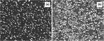
Fillers such as talc, montorillonite, carbon black, or hydroxyapatite were shown to accelerate the crystallization rate of PLA.Reference Huang, Hwang, Liu and Lin42, Reference Li, Hu, Wang and Shen43 Fibers have the same effect on the crystallization behavior of PLA, as noted for kenaf fibers and rice straw,Reference Dobreva, Perena, Pérez, Benavente and Garcìa44 and for CNTs.Reference Shieh, Twu, Su, Lin and Liu45 DSC was used to assess the nucleating ability of electrospun fibers. Isothermal crystallization was performed in the DSC instrument at T c = 110 °C, observing a crystallization exothermal curve. Such a pattern was linearized as better detailed in the experimental section,Reference Avrami30 and by fitting of the lines yielded by the experimental data, two parameters were obtained, which describe the crystallization kinetics: ln K, a kinetic constant, and n, a parameter related to the mechanism of nucleation and the dimensionality of growth in the crystallization.Reference Avrami30 The kinetic constant K was larger for the composites (lnK = −3.4 and −3.3 for PLANY1.5 and PLANY2.5, respectively) than for the matrix (lnK = −3.8). This implies that fibers have a nucleating effect, which was also confirmed by polarized light optical microscopy (PLOM). Figure 4 compares pictures taken after 20 min of isothermal crystallization at 100 °C for the neat matrix and for the sample PLANY1.5. As can be seen, a larger number of spherulites appeared in the fiber-containing material, and the crystallization process is much closer to completion in the composite, rather than in the matrix. In Fig. 4(b), it can be seen that the spherulites are preferentially concentrated around the fibers. This corroborates DSC data in evidencing a nucleating ability by electrospun fibers, which was previously observed also in the case of poly(caprolactone) matrices.Reference Neppalli, Marega, Marigo, Bajgai, Kim and Causin13 The Avrami parameter n remained constant at 1.6 in all samples, indicating that no significant changes in the mechanism of crystallization are observed by the addition of filler. This is somewhat different from what previously observed for other nanofillers, which often induced a modification of the crystallization mechanism.Reference Su, Guo, Liu, Li and Wu41, Reference Huang, Hwang, Liu and Lin42
Polarized light optical micrographs of the spherulitic texture obtained after 20 min of isothermal crystallization at 100 °C for (a) the neat matrix and for (b) sample PLANY1.5.

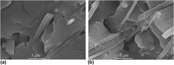
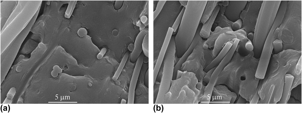
The adhesion between the matrix and the electrospun fibers was studied by observing the fractured surface of the samples using SEM. Figures 5 and 6 show that PLA and N6 fibers had a good compatibility with each other, resulting in well-embedded composite systems. Compared to composites of natural fibers and PLA,Reference Oksman, Skrifvars and Selin3, Reference Huda, Drzal, Misra and Mohanty5, Reference Meng, Hetzer and De Kee6, Reference Mat Taib, Ramarad, Mohd Ishak and Todo46 in this case a much better adhesion was attained. Especially when fibers were disposed perpendicularly to the fracture surface, the sections of fractured fibers were perfectly embedded within the PLA matrix. The entity of adhesion decreased in the regions of the composites where many fibers are oriented tangentially to the fracture surface [Figs. 5(b) and 6(b)]. Also in such zones of the sample, though, the fibers remained firmly rooted within the matrix, without the appearance of large craters or of debonded sites. The morphology of the composites studied in this work, especially of PLANY1.5, was somewhat different from the one previously observed in the case of PCL/N6 composites, where larger-diameter fibers showed a poor interfacial adhesion, and bundles protruded from craters in the matrix.Reference Neppalli, Causin, Marega, Saini, Mba and Marigo47 Interestingly, in the composites studied in this work, all the fibers displayed the same optimal adhesion, irrespective of their diameter. On the contrary, in the case of PCL/N6 composites the finest filaments were firmly embedded in the matrix, their exposed end protruding directly from within the matrix, without the presence of craters at their base due to debonding, which was the case in the largest-diameter fibers. Increasing the filler content, such as in the case of PLANY2.5, the morphology became more similar to the one previously observed in PCL/N6 composites, although also in PLANY2.5 adhesion is globally considered very good.
SEM images of PLANY1.5 in a region where fibers are preferentially positioned (a) perpendicular and (b) parallel to the fracture surface.

SEM images of PLANY2.5 in a region where fibers are preferentially positioned (a) perpendicular and (b) parallel to the fracture surface.

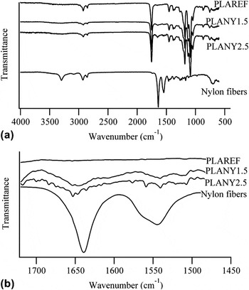
The quality of adhesion was also investigated by IR spectroscopy. Figure 7 shows a comparison of the IR spectra of samples PLAREF, PLANY1.5, PLANY2.5, and the electrospun N6 mat. Particular attention was posed to the signals at 3300 cm−1 (N–H stretching of nylon), at 1640 cm−1 (C=O stretching of nylon), and at 1540 cm−1 (N–H bending of nylon). The position and shape of such peaks are a function of the type and extent of hydrogen bonding which nylon molecules form. As may be seen, in the composites the signals due to the N–H bond of nylon, i.e., the stretching band at 3300 cm−1 and the bending peak at 1540 cm−1 are broadened and weakened so much that they disappear. On the other hand, the C=O stretching band moves from 1640 cm−1 in the neat fibers to 1647 cm−1 in the composites, indicating that the chemical environment of the amide groups of nylon is significantly modified by the interaction with the PLA matrix.
Infrared spectra of the reference matrix, composites, and neat nylon fibers. Part (a) shows the entire spectrum, part (b) shows an enlargement of the spectral region where the C=O stretching (∼1640 cm−1) and the N–H bending (∼1540 cm−1) bands of nylon appear.

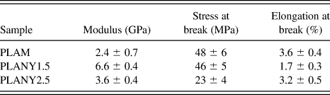
Differences in the semicrystalline framework and in interfacial adhesion between matrix and filler were reflected by the mechanical properties displayed by the samples. Table III summarizes the mechanical properties of the matrix and the composites. The materials were quite brittle, breaking before yielding, as expected from crystalline PLA. PLANY1.5, which was characterized by an optimal adhesion between matrix and fibers, with no bundles and with the thickest lamellae, increased its modulus almost 3-fold with respect to the matrix. This sample retained the stress at break of the matrix, whereas its elongation at break decreased. As often observed in nanocomposites, the increase in stiffness of the sample was obtained at the expense of its ductility.
Tensile mechanical properties of PLA and of its composites.
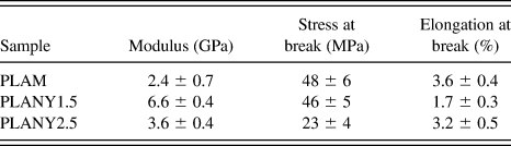
When the quantity of fiber bundles increased and the thickness of lamellae decreased, as in PLANY2.5, the effect of the fibers was weakened. However, this sample displayed an increase of modulus by 50% with respect to the matrix, without detrimental effects on elongation at break.
Similar results were obtained for natural fibers, although with a much larger filler content.Reference Graupner, Herrmann and Müssig4 Oksman and coworkers,Reference Oksman, Skrifvars and Selin3 for example, reported very similar mechanical properties as ours, but a content of 30% of flax fibers was necessary to achieve the same performance obtained with just 1.5% electrospun fibers. In another report by Misra and coworkers, 40% wood fibers were required to obtain a tensile performance similar to that of our composites.Reference Huda, Drzal, Misra and Mohanty5 Improvements in modulus slightly larger than those of our composites were obtained with ternary micro/nanocomposites containing, in addition to 40% wood fibers, also 5% nanoclay.Reference Meng, Hetzer and De Kee6
The approach chosen by Yano and coworkers, who used submicrometric fibrillated cellulose,Reference Suryanegara, Nakagaito and Yano8 brought about increases in tensile modulus and strength, although to a lesser extent than in the composites of the present work. When 3% microfibrillated cellulose was added, no significant increases in tensile modulus and strength were observed, and just elongation at break decreased. However, tensile modulus was increased by 60% and tensile strength by 10% with the addition of 10% microfibrillated cellulose.Reference Suryanegara, Nakagaito and Yano8
Simultaneous increases in tensile modulus and in elongation at break could be attained with small quantities of CNTs, which are, however, much more expensive than the electrospun fiber used in the composites described in the present work.Reference Chiu, Chang, Kuo, Lin and Wen11
The existence of an optimum level of filler, beyond which the properties decrease instead of increasing, is common in compositesReference Oksman, Skrifvars and Selin3 and nanocompositesReference Sinha Ray, Yamada, Okamoto and Ueda48–Reference Di, Iannace, Di Maio and Nicolais50 and is often associated to the effect of the presence of the filler on the crystallinity of the matrix.Reference Di, Iannace, Di Maio and Nicolais50
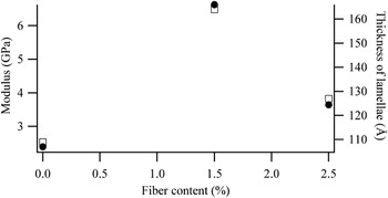
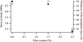
A number of authors stressed the importance of lamellar morphology in understanding the reasons of reinforcement.Reference Lincoln, Vaia, Wang, Hsiao and Krishnamoorti31, Reference Maiti, Nam, Okamoto, Hasegawa and Usuki39, Reference Truss and Yeow51 In particular, a correlation between tensile properties and lamellar features was previously noted for polyethylene and polypropylene composites filled with polyethylene-grafted multiwall CNTs and polypropylene-grafted CNTs, respectively.Reference Causin, Yang, Marega, Goh and Marigo34, Reference Causin, Yang, Marega, Goh and Marigo35 A clear relationship between lamellar features and mechanical properties was observed also in this case, as can be seen in Figs. 8 and 9.
Comparison of the trend of tensile modulus (closed circles) and of the thickness of lamellae (open squares) as a function of fiber content.

Comparison of the trend of stress at break (closed circles) and of the thickness of the amorphous layer between the lamellae (open squares) as a function of fiber content.

The trend of Young’s modulus as a function of filler content was the same as the trend of the lamellar thickness evaluated by SAXS (Fig. 8). Modulus is known to depend on the lamellar thickness and crystallinity.Reference Pukanszky, Mudra and Staniek52 In this case, lamellar thickness was the preponderant factor influencing modulus because although samples PLANY1.5 and PLANY2.5 have the same φ SAXS they displayed very different moduli.
Another example of correlation between lamellar morphology and tensile properties is shown in Fig. 9, which displays the stress at break and the thickness of the amorphous layer in lamellar stacks as a function of fiber content. Also in this case, the trends are very similar.
Multiple factors are critical for the tensile behavior of polymer-based composites, among which are dispersion, matrix–filler interactions, spherulitic texture, micromechanical deformation processes, skin-core structures, and morphological features. Although the data gathered in this work may not be sufficient to single out all of above factors, however, a role of the lamellar morphology is strongly evident.
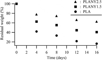
A particularly interesting effect of fibers was that of influencing the degradation behavior of the composites. Samples were exposed to degradation studies first in PBS for 4 months. Even after 4 months, samples showed negligible weight loss, i.e., 0.4%, in PBS. Subsequently, samples were moved to NaOH solution; in this medium, samples were degraded very rapidly compared to PBS. Figure 10 shows the trend of mass residue as a function of residence time in NaOH.
Residual weight of the samples as a function of residence time in NaOH solution.

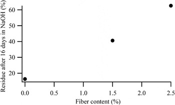
PLA was the sample which degraded more quickly, whereas addition of fibers made the composites more resilient to degradation. This effect is linear, as shown in Fig. 11, which displays the entity of the residue as a function of fiber content.
Residual weight of the samples at the end of the degradation experiments, as a function of fiber content.

It has already been reported that degradation happens through a hydrolysis mechanism and preferentially in the less ordered portions of the sample, so the semicrystalline framework can be key for the control of the degradation rate.Reference Neppalli, Causin, Marega, Saini, Mba and Marigo47, Reference Armentano, Dottori, Fortunati, Mattioli and Kenny53, Reference Zhou and Xanthos54 However, the semicrystalline morphology of the samples, i.e., the quantity of amorphous material at disposal for degradation was not so different to explain such divergence because PLANY1.5 and PLANY2.5 had different degradation rates, but a similar degree of crystallinity. The morphology of the fiber/matrix assembly could help in shedding light on this issue. Armentano and coworkersReference Armentano, Dottori, Fortunati, Mattioli and Kenny53 recently reviewed the effect of nanofillers on the degradation of biodegradable-polymer-based nanocomposites and highlighted the role of nanofillers in favoring the exchange of water within the composites, thereby increasing the rate of hydrolysis-based degradation mechanisms. A number of reports observed that clay-containing nanocomposites had a higher degradation rateReference Zhou and Xanthos54–Reference Paul, Delcourt, Alexandre, Degee, Monteverde and Dubois56 because such samples exhibited a high volume of polymer matrix in contact with the nanoclay edges and surface, resulting in easier water attack of the polymer chains compared to the unfilled polymer.Reference Zhou and Xanthos54
As previously noted, the composites displayed a very good interfacial adhesion between the matrix polymer and nylon fibers. Nylon fibers are not degraded by NaOH, so they acted as an obstacle to the diffusion of degrading solution inside the bulk of the sample. Obviously, the more the fibers, the more difficult it was for the NaOH solution to reach the inner regions of the composite. CNTs had the same effect; they acted as a physical barrier hindering the degradation process.Reference Wu, Wu, Zhou, Zhang and Yang10, Reference Mei, Zhong, Yang, Ouyang, Zhang, Hu, Ma, Lu, Ryu and Deng57 Moreover, the firm adherence between the fibers and the matrix inhibited the formation of channels at the interface, which could vehicle water inside the composite, favoring a more thorough and rapid degradation of the PLA matrix. Previous investigations on PCL containing both N6 and polyvinylpirrolidone (PVP) fibers indicated that such channels are very important for favoring degradation.Reference Neppalli, Marega, Marigo, Bajgai, Kim and Causin14 Despite being a water soluble and, therefore, readily biodegradable polymer, PVP fibers did not increase the degradation rate because they were very firmly embedded in the PCL matrix, so water could reach the fibers only after the surrounding PCL matrix was degraded, significantly slowing the whole process.Reference Neppalli, Marega, Marigo, Bajgai, Kim and Causin14 The increase in degradation rate was achieved using simultaneously PVP and nylon fibers, in which thinner PVP fibers tended to wrap around larger nylon fibers. In this case, the dissolution of PVP fibers formed channels at the interface between matrix and nylon fibers, which could vehicle water inside the composite, favoring a more thorough and rapid degradation of the PCL matrix.Reference Neppalli, Marega, Marigo, Bajgai, Kim and Causin14
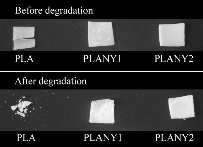
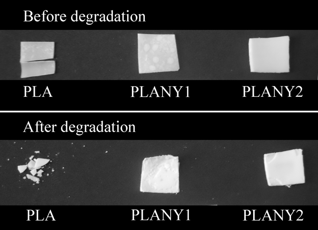
Another interesting feature was observed during degradation studies. Figure 12 shows the pictures of the samples before and after degradation in NaOH. The PLA matrix totally lost its shape, whereas, when nylon fibers were used, the composites displayed an excellent dimensional stability, even after a weight loss of 40–60% the shape was perfectly retained. This is important under an applicative point of view because it may allow the functionality of the biodegradable product also when the degradation process is quite advanced.
Images of the samples before and after degradation in NaOH solution.
IV. CONCLUSIONS
In this work, electrospun nylon fibers were used to prepare PLA-based composites by a very simple compression molding method. The aim of this work was to show the viability of electrospun fibers as fillers for fiber-reinforced composites, a still rather underdeveloped field.
Electrospun fibers showed an interesting potential for the property improvement of biodegradable polymeric matrices because they are able on one hand to shape the semicrystalline framework at a lamellar level, therefore influencing the mechanical properties of the material, and on the other hand to tune the degradation behavior. In other words, the interplay between good interfacial adhesion between matrix and filler and thickening of the lamellae induced by the presence of fibers allowed to increase the modulus of the composites 3-fold with respect to neat PLA, although at the expense of elongation at break. A larger quantity of fibers allowed to increase the modulus by 50% while retaining the same elongation at break of the pristine matrix. The electrospun fiber mat used in this work was nonwoven and unoriented, so the possibility to obtain oriented fibers promises to be even more effective for the control of the improvement of mechanical properties.
The morphology of matrix–filler interaction moreover slowed down the degradation rate of the material while improving the dimensional stability during the degradation process. This is a particularly interesting feature of the studied samples because it shows that the addition of electrospun fibers can be a way to tune the durability of PLA-based products, widening the range of application of this promising material.
A remarkable advantage of this approach is its flexibility. In fact, the possibility to engineer by electrospinning the chemical nature and the morphological features of the filler allows an accurate design of the composites. This contrasts with most commonly used nanofillers, which derive from naturally occurring materials (clays) or are less tunable in chemical nature (CNTs), limiting the potential for a detailed design of the material.
ACKNOWLEDGMENTS
Ramesh Neppalli is grateful to Fondazione Cassa di Risparmio di Padova e Rovigo for the support of his Ph.D. grant. This work was financed by the PRAT project of the University of Padova CPDA099194/09.