I. INTRODUCTION
Convection is well known to play a key role in affecting the solidification structure in solidification processing. Hence, the effective control of convection is required to achieve high-quality castings. A great deal of research has showed that convection due to thermal and compositional variation can cause the formation of channel-like and freckle segregation defects Reference Bergman, Fearn, Bloxham and Shannon1,Reference Yuan and Lee2 and variation in the dendrite spacing. Reference Dupouy, Camel and Favier3,Reference Lehmann, Moreau, Camel and Bolcato4 The impact of the convection forced by external conditions during solidification has also been investigated. Reference Medina, Du Terrail, Durand and Fautrelle5–Reference Steinbach and Ratke7 Particularly, the effect of magnetic fields on convection during directional solidification has been shown quite dramatically. Reference Youdelis and Dorward8–Reference Tewari, Shah and Song10 Indeed, Youdelis and Dorward Reference Youdelis and Dorward8 found that the value of the effective distribution coefficient (the ratio of the actual solute concentration in the solid to that in the liquid near liquid/solid interface) in directionally solidified Al–Cu alloys decreased with a 3.4 T transverse magnetic field, suggesting the magnetic field enhanced mass transport in the liquid. Moreau Reference Moreau, Laskar and Tanaka9 et al. showed that the application of a magnetic field during the dendritic solidification of metallic alloys produces strong flows around dendrites, and large freckles were observed. Tewari Reference Tewari, Shah and Song10 et al. observed that the application of a 0.45 T transverse magnetic field caused distortion in a cellular array, and the freckles formed during the directional solidification of Pb–Sn alloys. Subsequently, the quantitative experiments of the thermoelectric magnetic convection (TEMC) effect were studied. It was found that a local current due to the Seebeck effect appeared in the dendritic network, and its intensity depended on the electrical conductivity, the difference of thermoelectric (TE) power between the solid and the liquid, as well as the temperature gradient. Reference Lehmann, Moreau, Camel and Bolcato11 The influence of a static axial magnetic field on liquid/solid interface shape and cellular morphology was observed, and the experimental results showed that ring like structures were formed in the presence of a weak magnetic field. Reference Li, Fautrelle and Ren12
The present work aims to investigate the influence of a transverse magnetic field on the segregation and the growth of primary Al2Cu dendrites in directionally solidified Al–40 wt% Cu alloys. This may deepen the understanding of the effect of the transverse magnetic field on the solidification structures and expand the researches of Al–Cu binary alloy.
II. EXPERIMENTAL PROCEDURE
The Al–40 wt% Cu alloy used in this work was prepared by high-purity Al (99.99%) and Cu (99.99%) in a graphite crucible induction furnace. The molten alloy was heated to 950 °C, magnetically stirred for half an hour and then poured into a graphite mold of 3 mm in diameter and a length of 15 mm. The cast samples were removed from the graphite mold and encased in a high-purity corundum tube of 3 mm inside diameter and 200 mm long for the directional solidification experiment.
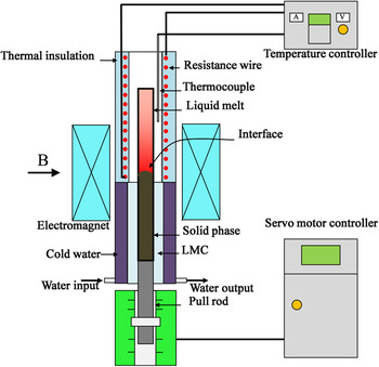
The experimental apparatus consisted of an electromagnet, a Bridgman–Stockbarger type furnace, a pulling velocity control unit and temperature controller. A schematic illustration of the experimental apparatus in a transverse magnetic field is shown in Fig. 1. The samples were directionally solidified in the furnace at a specified pulling velocity at various magnetic field intensities. The transverse static magnetic field was produced by an electromagnet with an adjustable intensity up to 1.0 T. To control the furnace temperature, a k-type thermocouple with a precision of ±1 K was placed in the furnace. A water-cooled cylinder containing liquid Ga–In–Sn metal (LMC) was used to cool the specimen. The temperature gradient in the sample was controlled by adjusting the furnace temperature, which was isolated from the LMC by a refractory baffle. The device was designed such that the specimen moves downwards while the furnace remains stationary. The pulling velocity was controlled by a servo motor and could be continuously adjusted between 0.5 μm/s and 1.5 cm/s. The temperature gradient in present study was 78 K/cm. During the directional solidification process, the samples in the corundum crucibles were pulled into the LMC cylinder after growing stability to cool the specimen immediately at room temperature to freeze the liquid/solid interface. Microstructures of the samples obtained from the experiments were investigated in etched condition post mortem by a Leica optical microscope (Wetzlar, Hesse, Germany).
Schematic illustration of the Bridgman solidification apparatus positioned inside an electromagnet.

The primary dendrite spacing, λ, was measured by the area counting method on transverse sections using the equation of λ = (A/N)0.5, where A is the actual area of the selected region, and N is the average number of primary dendrites in the area A. The area fraction of Al2Cu phase was measured by computer image software ImageJ. Reference Schneider, Rasband and Eliceiri13
III. EXPERIMENTAL RESULTS
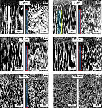
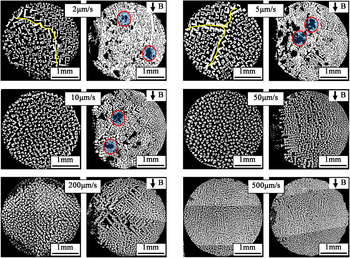
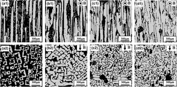
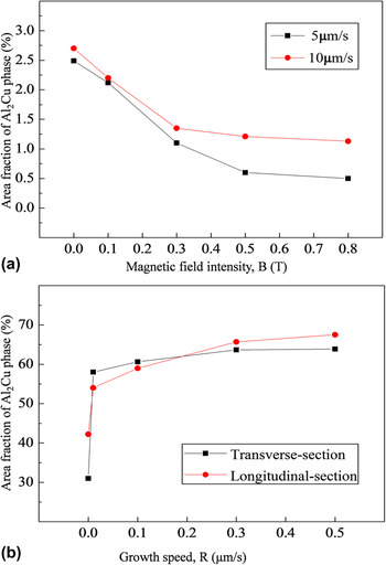
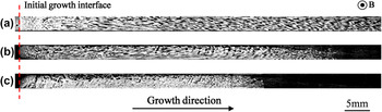
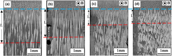
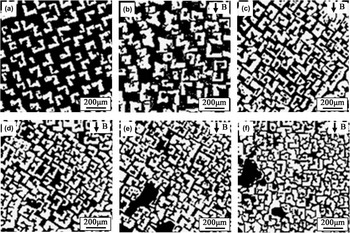
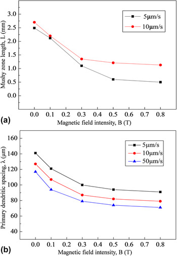
Figure 2 shows the longitudinal structures near the liquid/solid interface in directionally solidified Al–40 wt% Cu alloy at various pulling velocities without and with the application of a 0.5 T magnetic field. The corresponding transverse structures at the position of 10 mm behind the liquid/solid interface are shown in Fig. 3. The images were digitally enhanced by adjusting their contrast. The light and dark regions, respectively, denoted primary Al2Cu phases and Al–Al2Cu eutectic phases. The application of the magnetic field caused distortion in primary Al2Cu dendrites array and radial segregation formed. Indeed, along with the formation of freckle segregations, one side of the liquid/solid interface collapsed and a channel-like segregation appeared on this side of the sample. Moreover, the influence of the magnetic field on the structures became weak as the pulling velocity increased. Microstructures behind the eutectic isotherm in directionally solidified Al–40 wt% Cu alloy at a pulling velocity of 2 μm/s under various magnetic fields are shown in Fig. 4. As seen in the figures, remarkable coarsening of primary Al2Cu dendrites was observed under the magnetic field. Furthermore, the mergence of primary Al2Cu dendrites happened in the magnetic field of 0.5 T. The area fractions of Al2Cu phase in Figs. 3 and 4 were measured and the results are displayed in Fig. 5. The area fraction of Al2Cu phase increased with the magnetic field and the effect became weak with the increase of the pulling velocity. Figure 6 shows the evolution of the primary Al2Cu phase distribution along the growth direction in a directionally solidified Al–40 wt% Cu alloy at a pulling velocity of 5 μm/s under various magnetic fields. The application of a magnetic field resulted in a significant modification of the primary Al2Cu phase distribution and ultimately caused the disappearance of Al2Cu phase. Figure 7 shows the longitudinal structures near the liquid/solid interface in the directionally solidified Al–40 wt% Cu alloy at a pulling velocity of 10 μm/s, under various magnetic fields. The corresponding transverse microstructures at the position of 10 mm behind the liquid/solid interface are shown in Fig. 8. One can notice that the decrease of mushy zone length (length between the blue and red line in Fig. 7) and primary dendrite spacing occurred with the increase of the magnetic field intensity. The relevant parameters are measured in Fig. 9. The mushy zone length and the primary dendrite spacing decreased with the increase of magnetic field intensity until the magnetic field was up to 0.5 T. The difference of phenomena between 0.5 and 0.8 T magnetic field was not obvious.
Longitudinal structures near the liquid/solid interface in directionally solidified Al–40 wt% Cu alloy at various pulling velocities without and with a 0.5 T magnetic field (red boxes denote channel-like segregations, yellow box denotes diverging grains, B denotes direction of magnetic field).

Transverse structures at the position of 10 mm behind the liquid/solid interface in directionally solidified Al–40 wt% Cu alloy at various pulling velocities without and with a 0.5 T magnetic field (red circles denote freckles, yellow curves denote grain boundaries).

Microstructures behind the eutectic isotherm in directionally solidified Al–40 wt% Cu alloy at a pulling velocity of 2 μm/s under various magnetic fields: (a1 and a2) 0 T; (b1 and b2) 0.01 T; (c1 and c2) 0.1 T; (d1 and d2) 0.5 T.

Effect of a transverse magnetic field on the area fraction of Al2Cu phase in directionally solidified Al–40 wt% Cu alloy: (a) area fraction of Al2Cu phase as a function of the magnetic field intensity at a pulling velocity of 2 μm/s; (b) area fraction of Al2Cu phase as a function of the pulling velocities without and with a 0.5 T magnetic field.

The evolution of the primary Al2Cu phase distribution along the growth direction in a directionally solidified Al–40 wt% Cu alloy at a pulling velocity of 5 μm/s under various magnetic fields: (a) 0 T; (b) 0.1 T; (c) 0.5 T (the red line denotes the initial liquid/solid interface).

Longitudinal structures near the liquid/solid interface in directionally solidified Al–40 wt% Cu alloy at a pulling velocity of 10 μm/s under various magnetic fields: (a) 0 T; (b) 0.1 T; (c) 0.5 T; (d) 0.8T.

Transverse microstructures at the position of 10 mm behind the liquid/solid interface in directionally solidified Al–40 wt% Cu alloy at a pulling velocity of 10 μm/s under various magnetic fields: (a) 0 T; (b) 0.01 T; (c) 0.1 T; (d) 0.3 T; (e) 0.5 T; (f) 0.8 T.

Effect of the magnetic field intensity (B) on the mushy zone length and the primary dendritic spacing in a directionally solidified Al–40 wt% Cu alloy: (a) Mushy zone length as a function of the magnetic field intensity at a certain pulling velocity; (b) primary dendritic spacing as a function of the magnetic field intensity at a certain pulling velocity.

IV. DISCUSSION
A. Effect of a transverse magnetic field on the radial segregation during directional solidification
The results presented should be attributed to the TEMC induced by a transverse magnetic field during directional solidification. It is well known that in any material a temperature gradient ∇T produces a Seebeck electromotive force (S∇T), where S is the TE power of material. As the temperature at the tip of the primary phase may be higher than that at its base, a nonisothermal interface will form, and then a TE current may be generated in the system. The currents in the liquid phase can be expressed as Reference Lehmann, Moreau, Camel and Bolcato11 :
 $${j_{\rm{L}}} = {{{\sigma _{\rm{L}}}{\sigma _{\rm{S}}}{f_{\rm{L}}}} \over {{\sigma _{\rm{L}}}{f_{\rm{L}}} + {\sigma _{\rm{S}}}{f_{\rm{S}}}}}\left( {{S_{\rm{S}}} - {S_{\rm{L}}}} \right)\nabla T\quad ,$$
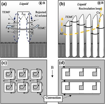
where σL and σS are electrical conductivity of the liquid and solid phases, f L and f S are the liquid and solid fractions, and S L and S S are the TE power of the liquid and solid phases. When the magnetic field is applied during directional solidification, the interaction between the magnetic field and the TE currents generates a Lorentz force (j L × B). This force will drive the liquid to move, also called TEMC. During directional solidification under a transverse magnetic field, the lateral convection TEMC will wash away the rich Al melt surrounding the interface of primary Al2Cu dendrites at microscopic scale, and induce recirculation loops in the bulk melt ahead and in the mushy zone to transfer Al from one side to another side of the sample along the direction of the TEMC at macroscopic scale, as shown Figs. 10(a) and 10(b). Consequently, a channel-like and freckle segregations form during directional solidification under a transverse magnetic field. Additionally, the TEMC in solidification has been modeled and the simulation results showed that TEMC could cause segregations. Reference Kao, Lee and Pericleous14,Reference Kao, Shevchenko, Roshchupinka, Eckert and Pericleous15 The above experimental phenomena validate these numeric results successfully.
Schematic illustration of the TEMC and its influence during directional solidification of the Al–Cu hypereutectic alloys under a transverse magnetic field: (a) TE current near the primary Al2Cu dendritic interface and induced TEMC in the liquid; (b) TEMC and induced recirculation loops near the sloping liquid–solid interface; (c) interdendritic convection induced by the TEMC; (d) coarsening and amalgamation of neighboring Al2Cu dendrites and the variation of convection.

A physical understanding of the process can be described by a famous local solute redistribution equation Reference Beckermann16 that describes the segregation formation in solidification due to the interdendritic convection.
 $${{{\rm{d}}{f_{\rm{s}}}} \over {{\rm{d}}{C_{\rm{L}}}}} = {{1 - {f_{\rm{s}}}} \over {{C_{\rm{L}}}\left( {1 - k} \right)}}\left( {1 - {{{u_{\rm{n}}}} \over {{v_{\rm{T}}}}}} \right)\quad ,$$
where f s is the solid volume fraction, C L is the solute concentration of the melt, k is the partition coefficient, u n is the melt flow velocity in the mushy zone, and v T is the liquidus isotherm velocity. Here, any solidification shrinkage is ignored. Since the Al2Cu is the primary phase, the C L would be decreasing (dC L < 0) during the generation of primary Al2Cu phase. The v T approximately equals the pulling rate whose absolute value is rather low when compared to that of u n. When k > 1 was considered, two different solute distribution processes for Al–Cu hypereutectic alloy happened. For the cases where the melt flow is same with the growth direction and u n > v T > 0, then df s < 0 and this means that the area fraction of Al2Cu phase is decreased. On the other hand, when u n < 0 < v T induced under the melt flow is opposite to the growth direction and df s > 0, which means that the area fraction of Al2Cu phase is increased. Therefore, a strip-like region without Al2Cu phase appeared on one side of the sample and the deformation of the solid/liquid interface is formed.
B. Effect of a transverse magnetic field on the growth of primary Al2Cu dendrites and the axial segregation
The growth of primary Al2Cu dendrites was also affected by the magnetic field. As seen in the Fig. 2, the primary Al2Cu dendrites along grain boundaries are much bigger than the ones within the grains at a lower pulling velocity, without the magnetic field. This particular morphology is due to the fact that the growth directions of the dendrites of the two neighboring grains are diverging, resulting in the formation of channel-like segregation. The enrichment of Al solute in the channel-like segregation leads to a concentration difference between the interdendritic liquid and the bulk liquid, whose horizontal component acts as a driving force for convection. Thus, the lateral growth of primary Al2Cu dendrites is enhanced by the convection. Reference Dupouy, Camel and Favier17 It is not difficult to understand that the TEMC achieves the same function as convection induced by concentration gradient to promote the lateral growth of primary Al2Cu dendrites, as shown Figs. 10(c) and 10(d). Study shows that the area fraction of the phase can approximately represent its growth during solidification. Reference Makkonen18 Therefore, the accelerated lateral growth of primary Al2Cu dendrites can be observed in the directional solidification process under the magnetic field.
In hypereutectic Al–Cu binary alloy, the content of solute Cu, x, can be calculated roughly by
 $$x = 0.0021f + 0.332\quad ,$$
where f is the area fraction of the primary Al2Cu phase. During the directional solidification, the axial segregation is caused by thermosolutal convection. Reference Ojha, Ding, Lu, Reye and Tewari19 Similarly, the recirculation loops induced by TEMC convey the Cu element from bulk melt to mushy zone and maintain the lateral growth of primary Al2Cu phase continuously. As a consequence, the transverse magnetic field will enhance the drop of solute Cu and the axial segregation during directional solidification.
C. Effect of a transverse magnetic field on primary dendrite spacing and mushy zone length
The decrease of the dendrite primary spacing due to natural Reference Dupouy, Camel and Favier3 or forced convection Reference Steinbach and Ratke7 was already observed experimentally. Lehmann Reference Lehmann, Moreau, Camel and Bolcato4 et al. developed a model explaining the effect of the convection on the primary dendrite spacing with an order of magnitude analysis. The relationship between convection and primary dendrite spacing was shown as follows:
 $$\lambda = {{{\lambda _0}} \over {\sqrt {1 + {U \mathord{\left/ {\vphantom {U R}} \right. \kern-\nulldelimiterspace} R}} }}\quad ,$$
where λ0 is the primary dendrite spacing without convection, U is velocity, and R is growth speed. This expression shows that the convection reduces the primary dendrite spacing. Similarly, as the application of the magnetic field during directional solidification induces the TEMC, the magnetic field will decrease the primary dendrite spacing. The mushy zone length, d, is defined as the distance between the eutectic front and the position of the highest dendrite tip. Using the constitutional supercooling criterion for binary alloy systems in the absence of convection, d is given by Reference Gündüz and Çadırlı20
 $$d \approx {{m\left| {{C_{\rm{E}}} - {C_{{\rm{Tip}}}}} \right|} \over {\nabla T}}\quad ,$$
where C E is eutectic composition, C Tip is the composition of dendrite tip, and m is the liquidus slope. It is not difficult to understand that the recirculation loops induced by TEMC drives the warmer liquid in the bulk melt into the mushy zone and thus enhances the rate of heat transfer to increase the temperature gradient (∇T). In another aspect, the rejected Al solute will go into the bulk melt ahead the mushy zone by these convections. The Al enriched melt can suppress the growth of primary Al2Cu dendrites. Therefore, the decrease of the mushy zone length under a magnetic field may be attributed to the enhancement of the heat transfer and solute transport caused by the TEMC.
The amplitude of the TEMC at various scales (i.e., sample and primary cell/dendrite scales) with the magnetic field during directional solidification of the Al–Cu alloys has been studied. Reference Li, Ren, Gagnoud, Budebkova and Fautrelle21 The results showed that the fluid velocity originally increases as B 1/2 and then decreases as B −1. There are u 1 and u 2, which correspond to the condition that the driving forces are balanced with inertia forces and the electromagnetic braking forces. The u 1 and u 2 are calculated by the following equations:
 $${u_1}{\rm{ = }}{\left( {\left. {{{\sigma S\nabla T\lambda B} \over \rho }} \right)} \right.^{1/2}}\quad ,$$
 $${u_2}{\rm{ = }}{{S\nabla T} \over B}\quad ,$$
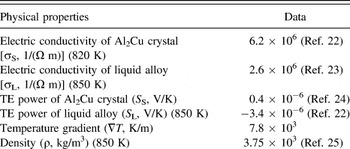
where σ, S, λ, and ρ, respectively, denote the electrical conductivity, the absolute TE power of the conducting medium, the typical length scale, and the density. The physical properties used in the evaluations are presented in Table I. The typical length scale λ approximately equals the primary dendritic spacing. It can be found that the maximum velocity of TEMC u max is achieved when the u 1 is equal to u 2. In this case, B max and the corresponding u max can be computed by
 $${B_{\max }} = {\left( {{{\rho S\nabla T} \over {\lambda \sigma }}} \right)^{{1 \mathord{\left/ {\vphantom {1 3}} \right. \kern-\nulldelimiterspace} 3}}}\quad ,$$
 $${u_{\max }} = {\left( {\left. {{{\lambda \sigma } \over \rho }{{\left( {S\nabla T} \right)}^2}} \right)} \right.^{{1 \mathord{\left/ {\vphantom {1 3}} \right. \kern-\nulldelimiterspace} 3}}}\quad .$$
Physical properties of the Al–Cu alloy used in the evaluation.

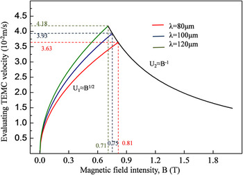
Evaluation results (see in Fig. 11) reveal that the change of typical length scale λ have an important influence on the velocity of TEMC. Indeed, the dendrite spacing and the mushy zone length decreased markedly as the magnetic field increased when the applied magnetic field is less than 0.5 T. However, the decrease of typical length scale in turn results in the weaker variation trends of these parameters. Therefore, the dendrite spacing and the mushy zone length decreased markedly as the magnetic field increased and the effect became weak with the decrease of typical length scale.
Curves of evaluating TEMC velocity varying with magnetic fields for different typical scales.

V. CONCLUSIONS
The influence of a transverse magnetic field on the solidification structure in directionally solidified Al–40 wt% Cu alloys was studied. The results obtained that a transverse magnetic field caused radial segregation during directional solidification, and thus a channel-like and freckle segregations formed during directional solidification under the magnetic field. At the same time, the application of a transverse magnetic field benefited the growth of the primary Al2Cu dendrites and caused the change of axial redistribution during the solidification process. Furthermore, the magnetic field decreased the mushy zone length and the primary dendrite spacing, and these effects weaken with the increase of the magnetic field intensity. The above results may be attributed to the TEMC-driven heat transfer and solute transport in the mushy zone.
ACKNOWLEDGMENTS
This work is supported partly by the European Space Agency through the Bl-inter 09_473220, National Natural Science Foundation of China (Nos. 51271109 and 51171106), and the Program for Professor of Special Appointment (Eastern Scholar) at Shanghai Institutions of Higher Learning.