





1. Introduction
The phenomenon of liquid spreading along a solid surface by displacing gas is termed dynamic wetting. This process occurs ubiquitously in nature, everyday experiences and various technological applications such as coating and printing. The extensive relevance of the wetting process highlights its practical significance. At the wetting front, three interfaces between each pair of the three materials intersect, forming a contact line region. When the influence of surface tension is significant, as indicated by a small capillary number (Ca), the dynamics of the contact line become important for the entire flow. This is because the contact angle, acting as a boundary condition, shapes the fluid interface (Dussan Reference Dussan1979, Reference Dussan1983; Ngan & Dussan Reference Ngan and Dussan1989). In this context, the contact line dynamics emerges as the fundamental problem of wetting.
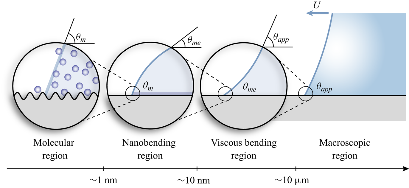
Understanding the physics of a moving contact line is challenging owing to its multiscale features (De Gennes, Hua & Levinson Reference De Gennes, Hua and Levinson1990; Snoeijer & Andreotti Reference Snoeijer and Andreotti2013; Wang Reference Wang2019). Usual optical measurements can capture the interface profile only at a resolution poorer than several microns, leaving the crucial details at finer scales unresolved. The angle between the interface and the substrate, accessible through optical measurements, is known as the macroscopic or apparent angle  $\theta _{app}$. During wetting or dewetting,
 $\theta _{app}$ deviates from its equilibrium value
 $\theta _e$, a deviation attributed to contributions from various scales. In a bottom-up manner, at the molecular level, the microscopic contact angle demonstrates velocity dependence owing to molecule jumping activities as explained by molecular kinetic theory (MKT) (Blake & Haynes Reference Blake and Haynes1969). Beyond the molecular region is the nanobending region, a convex nanoscopic structure (Chen, Yu & Wang Reference Chen, Yu and Wang2014; Wang Reference Wang2019) that links the microscopic angle
 $\theta _m$ with the macroscale region. Chen et al. (Reference Chen, Yu and Wang2014) recently revealed this mesoscopic link of advancing contact lines using tapping mode atomic force microscopy (AFM). The curvature of the nanobending structure and
 $\theta _m$, the root of the nanobending region, are both velocity dependent. The mesoscopic angle,
 $\theta _{me}$, is defined at the end of the nanobending region, which is measured to be 20 nm in height. Beyond this level, the Ca-dependent concave viscous bending becomes prominent, forming the main focus of hydrodynamic models (Voinov Reference Voinov1977; Cox Reference Cox1986). The multiscale structure of the complex contact line is depicted in figure 1.
Sketch of the multiscale structure of the contact angle during advancing.
In practical situations, the interest usually lies in the dependence of the apparent contact angle  $\theta _{app}$ on the contact line velocity
 $U_{CL}$, rather than its complex origins involving different dissipation channels at various scales, such as molecular friction and viscous dissipation. From another perspective, the relation between the dynamic contact angle and contact line speed is also important for modelling macroscale flows with moving contact lines. Imposing a prescribed (velocity-dependent) interfacial angle as a boundary condition can address the microscopic effects on the macroscopic flow (Sui & Spelt Reference Sui and Spelt2013; Malgarinos et al. Reference Malgarinos, Nikolopoulos, Marengo, Antonini and Gavaises2014; Sui, Ding & Spelt Reference Sui, Ding and Spelt2014). This approach relaxes the requirement to resolve nanoscale/microscale details near the contact line, making it an alternative to computationally expensive highly resolved directional numerical simulations (Liu et al. Reference Liu, Vandre, Carvalho and Kumar2016; Fullana, Zaleski & Popinet Reference Fullana, Zaleski and Popinet2020). These considerations drive our interest in exploring the constitutive relation between the dynamic contact angle and contact line velocity in this study. Empirical observations commonly suggest a nonlinear connection between the macroscopic contact angle and velocity (Hoffman Reference Hoffman1975; Dussan Reference Dussan1979). While in many cases Hocking's linear law (Hocking Reference Hocking1987), which relates the deviation of the contact angle from equilibrium and the contact line velocity through a real number
 $\lambda$, is an adequate approximation to capture the dynamic contact line behaviour, i.e.
 \begin{equation} U_{CL} = \lambda(\theta_d - \theta_e), \end{equation}
where the slope  $\lambda$ is termed different names in various studies, like capillary coefficient (Cocciaro, Faetti & Festa Reference Cocciaro, Faetti and Festa1993; Ting & Perlin Reference Ting and Perlin1995; Perlin, Schultz & Liu Reference Perlin, Schultz and Liu2004) and mobility (Xia & Steen Reference Xia and Steen2018; Ludwicki et al. Reference Ludwicki, Kern, McCraney, Bostwick, Daniel and Steen2022). By transforming the conventional
 $\Delta \theta -U_{CL}$ diagram of an oscillating wetting line into a
 $\Delta \theta \eta -U_{CL}\eta$ diagram, where
 $\Delta \theta = \theta _d - \theta _e$ represents the deviation of the contact angle from its equilibrium value and
 $\eta$ represents the contact line displacement, Xia & Steen (Reference Xia and Steen2018) noted that the slope
 $\lambda$ remains a real constant in the regions away from the stick slip and can function as a phenomenological parameter for evaluating contact line mobility.
However, the behaviour of the contact line is influenced not only by the localized material properties of three-phase systems but also by the dynamics of the flow. It has been noted that the boundary condition for unsteady flow should differ from that of steady situations (Miles Reference Miles1990; Ting & Perlin Reference Ting and Perlin1995; Jiang, Perlin & Schultz Reference Jiang, Perlin and Schultz2004; Perlin et al. Reference Perlin, Schultz and Liu2004). Hocking, in the study of the contact line problem for a surface wave, implicitly considers the contact angle and contact line velocity to be in phase by assigning the capillary coefficient  $\lambda$ as a real constant (Hocking Reference Hocking1987; Miles Reference Miles1990; Cocciaro et al. Reference Cocciaro, Faetti and Festa1993). Miles (Reference Miles1990) suggests that for unsteady contact line motion, the slope
 $\lambda$ in Hocking's linear law becomes a complex function of frequency, thereby introducing a phase offset between the contact angle and contact line velocity. This results in the formation of a hysteresis loop in the
 $\theta -U_{CL}$ diagram, as illustrated in figure 2 and also figure 4 of Perlin et al. (Reference Perlin, Schultz and Liu2004).
Illustration of the hysteresis loop in the  $\theta -U_{CL}$ diagram predicted by Miles’ model.

In the investigations of oscillating contact lines on vertical walls composed of different materials (glass and stainless steel), Perlin and the collaborators (Ting & Perlin Reference Ting and Perlin1995; Perlin et al. Reference Perlin, Schultz and Liu2004) observed a complex angle–velocity correlation resembling an inverted ‘T’ with a loop formed at the base. They experimentally evaluated the parameter  $\lambda$, revealing its time-dependent nature. The openness of the angle–velocity curve is also observed in the contact line behaviour of an oscillating drop on a fluorinated surface in the work by Xia & Steen (Reference Xia and Steen2018). However, Xia and Steen's analysis omits the hysteresis loop and attributes it simply to dissipation, which is contradicted by the results of the current study. Another example of the open hysteresis loop is documented in the molecular dynamics (MD) simulation conducted for an oscillating Wilhelmy plate experiment by Jin, Koplik & Banavar (Reference Jin, Koplik and Banavar1997). They correlated the contact angle with the force exerted by the liquid on the solid wall and observed a hysteresis loop in the force–velocity diagram on a microscopically rough surface. In their study, this phenomenon is attributed to the broadening of the interface on the rough surface.
Upon the brief discussion, it is evident that the dynamic contact angle may not be in phase with the contact line velocity in the case of an unsteady motion. Consequently, the contact line behaviour deviates from that observed in steady motion, defying a description by a single-valued function connecting angle and velocity. To comprehend the dynamics of the contact line under unsteady conditions, this study explores the mobile contact line of a sessile droplet supported by a vertically vibrating substrate through experiment. Our observations reveal a distinct hysteresis loop in the oscillatory contact line behaviour, which we term ‘dynamic hysteresis’, distinguishing it from the static hysteresis defined as the interval between the critical advancing and receding angles. This dynamic hysteresis is related to the time retardation between the contact angle and contact line velocity. Through various surface molecule modifications, it becomes apparent that the dynamic hysteresis is sensitive to static hysteresis. Notably, we establish that the dynamic hysteresis remains unrelated to the magnitude of the contact line friction coefficient, indicating that it is not attributable to dissipative effects. Furthermore, we made attempts from various perspectives to determine suitable models for predicting the behaviour of an oscillatory contact line. First, we generalize Hocking's linear law by making the coefficient  $\lambda$ a function of the time derivative of the logarithm of contact line velocity. Next, we assessed the dynamic hysteresis predicted by a modified generalized Navier boundary condition (GNBC), which intrinsically encompasses the time derivative of the contact angle due to the velocity gradient term.
This study explores the intriguing phenomena associated with oscillating contact lines. The molecular-scale interaction between the liquid and solid materials in the proximity of an oscillating contact line not only impacts the dissipation rate but also contributes to the memory effect on the dynamic contact angle. In this context, the constitutive law for the dynamic contact angle should incorporate acceleration in addition to contact line velocity.
2. Experimental method
2.1. Oscillatory wetting experiment
The test rig of the oscillatory wetting experiments is depicted in figure 3(a). In this configuration a  $10\ \mathrm {\mu }{\rm L}$ pure water droplet is placed on the substrate sample, which is affixed horizontally to a vertically vibrating stage. The vibration frequency is set at 70 Hz, close to the resonance frequency of
 $[2, 0]$ axisymmetric mode (Bostwick & Steen Reference Bostwick and Steen2014), determined through a rough frequency sweep. To isolate and highlight the influence of substrate-related factors, we maintain a constant frequency. This aims to prevent the introduction of effects arising from the change of Stokes viscous layer, the thickness of which is denoted by
 $\delta = \sqrt {\mu /\rho \omega }$. Driven by the axisymmetric bulk motion, the contact line advances and recedes periodically, along with the dynamically changing contact angle (refer to figure 3b). The mechanical vibration system comprises a function generator (low-frequency power oscillator URP-20, SHIMADZU) and a mechanical vibrator (mechanical wave driver SF-9324, PASCO scientific).
(a) The test rig of the oscillatory wetting experiment. (b) Illustration of the local contact line movement on a monolayer modified substrate.

To capture the transient contact line movement, a high-speed camera (Phantom VEO710L, Vision Research Inc.) equipped with a Tamron SP AF 180mm F/3.5 Di macro lens (Tamron USA, Inc., Commack, NY) is employed, illuminated by a backlight lamp (HVC-SL, Photron). The frame rate is set at 7000 fps. The high-speed visualization system is enhanced with a  $5{\times }$ objective lens (OLYMPUS LMPLFLN), improving the spatial resolution to
 $3\ \mathrm {\mu }{\rm m}\ {\rm pixel}^{-1}$.
2.2. Image analysis
To automatically extract the dynamic contact angle and contact line position from the high-speed video frame by frame, we have developed a customized MATLAB program based on the polynomial fitting approach. Here we provide a brief overview of the three main steps of our program; for detailed information, refer to the supplementary material.
(i) Extracting the drop boundary using a Canny edge detector and obtaining a set of pixel coordinates representing the drop boundary.
(ii) Identifying the vertical and horizontal contact line coordinates by employing the profile method (Kalantarian et al. Reference Kalantarian, David, Chen and Neumann2011).
(iii) Approximating the drop profile using a fourth-order polynomial curve fitted with 200 pixels along the drop boundary above the contact point within the polar coordinate system (Atefi, Mann & Tavana Reference Atefi, Mann and Tavana2013). Then the contact angle is estimated as the derivative of the fitted polynomial at the contact point.
Additionally, the contact line velocity is computed as the time derivative of the contact line's horizontal position using central differencing. An illustrative example of an oscillatory moving contact line, accompanied by dynamic plots depicting the motion of the contact line in three distinct phase planes, is provided in supplementary movie 1.
2.3. Substrate preparation
Silicon wafers were first cut into  $2\ {\rm cm}\times 2\ {\rm cm}$ chips to serve as substrates. Prior to surface modifications, silicon chips were sequentially cleaned in ultrasonic baths of acetone, ethanol, distilled water for 5 min each and then dried with nitrogen gas. Following the cleaning process, a 15-min ozone plasma treatment was applied to the samples to remove organic contaminants and to enhance the adhesive property of the surfaces.
In our experiments, four kinds of molecules were used for modification of the substrates: trichloro(3,3,4,4,5,5,6,6,7,7,8,8,8-tridecafluorooctyl)silane (FUJIFILM Wako Pure Chemical Corporation, JP), referred to as fluoroalkyl silane (FAS), trimethylsiloxy terminated polydimethylsiloxane (PDMS, M.W. 2000) (Thermo Fisher Scientific, USA) and two alkyl silanes with distinct lengths – trimethoxy-n-octylsilane (AS-C8) (FUJIFILM Wako Pure Chemical Corporation, JP) and octadecyltrimethoxysilane (AS-C18) (FUJIFILM Wako Pure Chemical Corporation, JP). These molecules are grafted to silicon chips through different procedures according to different chemisorption mechanisms.
Fluoroalkyl silane was grafted onto silicon using the vapour phase deposition approach. The silicon chip and vapourized fluoroalkyl silane reacted in a vacuumized desiccator at room temperature for 2 h, ensuring that the substrate reached a state of saturated hydrophobicity. The alkyl silanes were coated on silicon through an immersion technique. The silicon chip was immersed in a toluene solution containing  $0.5\ {\rm mM}\ {\rm L}^{-1}$ alkyl silane at room temperature for 18 h, catalyzed by HCl. After the reaction, the surfaces were rinsed by toluene, ethanol and distilled water in order.
The PDMS is covalently attached to the silicon substrate by heat treatment. The silicon chip was wetted by the undiluted PDMS melt in a capped vial and subsequently baked in an oven at  $100\,^{\circ }{\rm C}$ for 24 h. Following the reaction, the surfaces were rinsed in a sequential order using toluene, ethanol and distilled water.
Lastly, bare silicon substrates without a monolayer were included for comparative analysis. In this case, the silicon chip was immersed in a 50 % HF solution for 10 min to remove the native oxide layer. This treatment increases the static contact angle of the bare substrate, which is preferred in our zoomed visualization system.
All the substrate samples used in the drop oscillation experiments were freshly made within 2 days to avoid aging effects of the grafted molecule layer.
2.4. Substrate characterization
The static contact angle and contact angle hysteresis (CAH) were assessed using a high-precision automatic contact angle metre (DropMaster, model DMo-602, Kyowa). The equilibrium contact angle  $\theta _e$ is measured by circular fitting of the drop's contour (axisymmetric), captured from a side view after gently depositing a
 $10\ \mathrm {\mu }{\rm L}$ water droplet on the targeted sample. The CAH is measured through the tilt plate method (Butt et al. Reference Butt2022) with the same water droplet. The thickness of the monolayer grafted onto the silicon chip was determined using a spectroscopic ellipsometer (M-2000U, J.A. Woollam). The static wetting properties and monolayer thickness of various surfaces are summarized in table 1.
Wetting properties and monolayer thickness of various surfaces.

3. Results
Conventionally, the behaviour of the contact line is described by a single-valued dependence of the dynamic contact angle  $\theta _d$ on the contact line velocity
 $U_{CL}$. However, by performing oscillatory wetting experiments on substrates modified by various molecules, a distinct hysteresis loop has been identified in the angle–velocity correlation, indicating the impact of memory effect on the oscillatory contact line movement.
3.1. Hysteresis loop
To study the contact line behaviour in a holistic way, we graph the trajectory of the cyclic contact line movement in a three-dimensional phase space. The three dimensions correspond to contact line displacement, contact line velocity and dynamic contact angle, respectively, as shown in figure 4(a). The circulation occurs in a clockwise direction when viewed from top to bottom. The primary distinction in the phase trajectories of the contact line motion on silicon and PDMS-coated surfaces is evident in their projection on the angle–velocity plane. On the PDMS-modified surface, the correlation between  $\theta _d$ and
 $U_{CL}$ is nearly single valued, resembling the conventional contact line relation observed in unidirectional motion (Dussan Reference Dussan1979). In contrast, the angle–velocity relation is more complex on a bare silicon substrate, presenting as a hysteresis loop. Similarly, the dynamic hysteresis is observed on fluoroalkyl silane and alkyl silane modified surfaces, although the loop exhibits distinct features across different surfaces; see figure 4(b).
(a) Three-dimensional plotting of phase planes consisting of contact angle, contact line velocity and contact line position. (b) Angle–velocity relation of different surfaces. The arrows in the figures indicate the system's evolution over time.

To quantitatively compare the dynamic hysteresis across different substrates, we characterize the hysteresis loop by calculating the ratio between the area enclosed by the angle–velocity curve and the rectangular area enclosed by the four extrema. This is illustrated in the inset of figure 5(b). In this manner, we have determined that the dynamic hysteresis depends on the surface material and is not influenced by the bulk flow. This is clearly illustrated in figure 5(b), where the x axis represents the peak acceleration of substrate vertical vibration  $a_Y$, which is calculated as
 \begin{equation} a_Y = (2{\rm \pi} f)^2Y_{amp}. \end{equation}
By tuning the amplitude of the plate vibration  $Y_{amp}$, the flow condition is adjusted in response to different plate accelerations. There is no obvious correlation between the dynamic hysteresis and the plate acceleration, indicating that the dynamic hysteresis is not flow dependent. Meanwhile, dynamic hysteresis systematically varies across different substrates. The PDMS-coated surface exhibits the lowest dynamic hysteresis, approaching almost a single-valued curve. In contrast, the bare silicon chip displays the largest dynamic hysteresis in the angle–velocity diagram, while fluorinated alkyl silane and alkyl silane result in a moderate level of dynamic hysteresis, falling between PDMS and silicon.
(a) Static wetting properties of different substrates. (b) Quantified dynamic hysteresis of different substrates. Inset: illustration of dynamic hysteresis quantification using the normalized area.

Figure 5(a) depicts the static wetting properties of various substrates. A comparison between figures 5(a) and 5(b) reveals that the dynamic hysteresis of tested surfaces mirrors a similar trend to the static hysteresis. The ranking is as follows: silicon > fluoroalkyl silane > alkyl silane > PDMS. The ranking of static hysteresis to some extent reflects the flexibility of the surfaces. The brush-like PDMS is highly flexible, rendering a liquid-like property to the surface and resulting in the lowest static CAH (Wooh & Vollmer Reference Wooh and Vollmer2016; Chen et al. Reference Chen, Huang, Ras and Tian2023). In contrast, the chain lengths of alkyl silane and fluoroalkyl silane in our experiments are significantly shorter than the PDMS brush, leading to reduced chain mobility in the grafted layer (Chen et al. Reference Chen, Huang, Ras and Tian2023). Additionally, the fluorocarbon chain is inherently ‘stiffer’ than its hydrocarbon counterpart (Eaton & Smart Reference Eaton and Smart1990). Finally, the bare silicon chip can be considered inflexible, given the presence of only nanoscale solid asperities on the surface, consequently leading to the highest CAH. However, the relationship asserted here between the hysteresis and the flexibility of the surface layer is qualitative. The rigorous validation of this trend through complex characterization is beyond the scope of this study.
3.2. Phase difference
Figure 6 presents the time histories of contact line velocity and dynamic contact angle for two representative cases, namely bare silicon and PDMS-coated surfaces. The comparison emphasizes a phase delay of the velocity signal to the contact angle on the silicon surface. This phase difference can be expressed as
 \begin{equation} \theta_d(t) = f[U(t - \tau)]. \end{equation}
Time evolutions of the contact angle and contact line velocity on a silicon substrate (a) and a PDMS coated substrate (b).

It is crucial to exercise caution when comparing the direct time history of different variables, given that the shapes of these signals are non-standard and do not conform to typical sinusoidal or square wave patterns. An approximate analysis may result in the loss of phase information. In a study by Cocciaro et al. (Reference Cocciaro, Faetti and Festa1993), the contact angle signal was approximated as a square wave when investigating the contact line effect on standing surface waves. Their findings indicate a  ${\rm \pi} /2$ phase difference between the contact angle and contact line displacement signals, leading to the conclusion that the contact angle is in phase with the contact line velocity. Based on this observation, they suggest that the capillary parameter
 $\lambda$ in Hocking's linear law should be treated as a real number.
For this consideration, we take an alternative approach to evaluate the phase difference between the velocity and angle signals. We found that the hysteresis loop can be closed by shifting the velocity signal forward for a duration  $\tau$, establishing that the contact angle
 $\theta _d$ is in phase with the variable
 $(U - \tau \dot {U})$, where
 $\dot {U}$ represents the contact line acceleration obtained through the time derivative of
 $U$ using central differencing. In this context, the dynamic contact line behaviour can now be described by a single-valued function
 \begin{equation} \theta_d = f[U(t - \tau)] = f(U - \tau\dot{U}). \end{equation}
The closure of the hysteresis loop is illustrated in figure 7(a).
(a) Examples showing the closure of the hysteresis loop by shifting the velocity signal forward for a duration  $\tau$. (a,b) Silicon substrate, (c,d) fluoroalkyl silane coated substrate. (b) Retardation time
 $\tau$ of different substrates at different substrate accelerations. (c) Retardation measured for different drop volumes. (d) Correlation between retardation and static hysteresis. The circular markers represent the original values under different accelerations and the diamond markers represent averaged values.

Note that Ting & Perlin (Reference Ting and Perlin1995) also acknowledged the contribution of contact line acceleration to the dynamic contact angle, which, however, is considered in the sense that the acceleration is the derivative of velocity. In addition, in concerns of calculation error, they opted not to conclusively establish the relationship between the dynamic contact angle and contact line acceleration. In (3.3) we illustrate that the acceleration  $\dot {U}$ contributes to
 $\theta _d$ owing to the retardation between angle and velocity. The relationship between
 $\theta _d$ and
 $\dot {U}$ extracted in our experiments is depicted in figure SM 3 of the supplemental material, exhibiting a ‘
 $Z$’ shaped loop among various surfaces.
The determination of  $\tau$ involves a search algorithm conducted iteratively as follows:
 $\tau$ values are systematically calculated within a roughly estimated range with intervals of 0.001 ms. Ultimately, the optimal retardation value,
 $\tau$, is selected based on the minimum absolute area enclosed by the curve of
 $(U - \tau \dot {U})$ vs
 $\theta$.
To identify the factors influencing retardation time, several variables were examined. Figure 7(b) presents a summary of the extracted  $\tau$ values across various surfaces and substrate accelerations, where the substrate vibration amplitude was varied while keeping the frequency unchanged. The data suggest that
 $\tau$ is largely insensitive to amplitude variations. To find out whether the oscillation frequency affects
 $\tau$, instead of directly tuning the substrate frequency, we varied the dimensionless frequency by adjusting the drop size, thereby changing the natural frequency,
 $\omega _c = \sqrt {{\gamma }/({\rho R_0^3})}$, where
 $R_0$ is the radius of the spherical cap-shaped drop. This approach was taken to maintain a consistent Stokes layer. The results in figure 7(c) suggest that the retardation's dependence on drop volume or dimensionless oscillation frequency is surface dependent. On the PDMS brush coated surface, the retardation time
 $\tau$ is consistently low and stable, with no apparent dependence on drop volume. While on both the fluorosilane-coated surface and bare silicon chip, the retardation time exhibits larger fluctuations compared with PDMS but does not show a clear trend with respect to drop size, and thus, non-dimensional frequency. In addition, a strong correlation between retardation
 $\tau$ and static hysteresis is observed, as shown in figure 7(d), where retardation time is positively related to static hysteresis.
3.3. Contact line friction
The experimentally extracted angle is the macroscopic angle  $\theta _{app}$, and its variation with contact line velocity is influenced by both viscous friction in the viscous bending region and local frictional dissipation at the molecular scale. Instead of distinguishing between different dissipation channels, calculating the total dissipation is of practical interest. The total dissipation rate can be determined by considering that dissipation during contact line movement is entirely attributed to effective contact line friction. In this context, we introduce a method for experimentally deriving the contact line friction coefficient through cyclic contact line movement.
During one cycle of the cyclic motion, the total work done by the unbalanced Young's force is
 \begin{equation} D_Y = 2{\rm \pi}\int\gamma(\cos{\theta_e} - \cos{\theta_d})r\,{\rm d}r. \end{equation}
The dissipation at the contact line is accounted for in the form of friction:
 \begin{equation} D_f = 2{\rm \pi}\int\mu_f U_{CL}r\,{\rm d}r. \end{equation}
Given the prominence of contact line dissipation as the primary contributor to total dissipation (Amberg Reference Amberg2022), the integrated form of  $\mu _{f}$ can be deduced by equating the total mechanical work to the frictional dissipation. Meanwhile, assuming a constant contact line friction coefficient and factoring it out from the integrand, the expression of
 $\mu _{f,int}$ is
 \begin{equation} \mu_{f,int} = \frac{D_Y}{2{\rm \pi}\displaystyle\int U_{CL}r\,{\rm d}r}. \end{equation}
This can be calculated as the ratio of the area enclosed by the square in figure 8(a) to the area enclosed by the circle in figure 8(b). Utilizing the same energy balance relation in a discrete manner, the calculation of the discrete contact line friction coefficient is expressed as
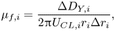 \begin{equation} \mu_{f,i} = \frac{\Delta D_{Y,i}}{2{\rm \pi} U_{CL,i}r_i\Delta r_i}, \end{equation}
where  $\Delta D_{Y,i}$ represents the mechanical work done by the unbalanced Young's force within a discrete step
 \begin{equation} \Delta D_{Y,i} = 2{\rm \pi}\gamma(\cos{\theta_e} - \cos{\theta_{d,i}})r_i\Delta r_i, \end{equation}
and the discrete frictional dissipation is
 \begin{equation} \Delta D_{f,i} = 2{\rm \pi}\mu_{f,i}U_{CL,i}r_i\Delta r_i. \end{equation}
Evaluation of contact line friction coefficient. (a) The total mechanical work done by the unbalanced Young's force. (b) Frictional dissipation divided by  $\mu _{f,int}$.

The integrated form and discrete form of the contact line friction coefficient  $\mu _f$ are not independent from each other, but they can be related through the total work done by the uncompensated Young's force over a complete period:
 \begin{equation} \mu_{f,int}\left(\sum_{i=1}^N U_{CL}r_i\Delta r_i\right) =\sum_{i=1}^N \mu_{f,i}U_{CL,i}r_i\Delta r_i. \end{equation}
Therefore,
 \begin{equation} \mu_{f,int} = \frac{\sum_{i=1}^N \mu_{f,i}U_{CL,i}r_i\Delta r_i} {\sum_{i=1}^N U_{CL}r_i\Delta r_i}=\sum_{i=1}^N \left(\frac{U_{CL,i}r_i\Delta r_i}{\sum_{i=1}^N U_{CL}r_i\Delta r_i}\right)\mu_{f,i} = \sum_{i=1}^N \frac{\Delta S_{f,i}}{S_f}\mu_{f,i}. \end{equation}
According to (3.11), the integrated  $\mu _{f,int}$ is a weighted average of discrete
 $\mu _{f,i}$, where the weight corresponds to the ratio of frictional dissipation in one step to that in a whole period. During a single discrete step, the discrete contact line friction coefficient can be treated as a constant. The cycle-averaged friction coefficient
 $\mu _{f,int}$ provides an overall estimation of the dissipation characteristics within a three-phase contact line system. In conjunction, the discrete coefficient
 $\mu _{f,i}$ offers instantaneous information about the resistance encountered during contact line motion. The experimental evidence presented in Appendix A (see figure 11) emphasizes the dynamic nature of
 $\mu _{f,i}$.
Figure 9 presents the integrated contact line friction coefficient across various surfaces. In figure 9(a) a noticeable flow-dependent trend is observed as the integrated  $\mu _{f,int}$ decreases with increasing substrate acceleration. From figure 9(b) we note a lack of correlation between the magnitude of contact line friction and dynamic hysteresis. This challenges the assumption that the openness of the hysteresis curve is attributable to dissipative effects (Xia & Steen Reference Xia and Steen2018). Noteworthy differences emerge among surfaces, with the bare silicon surface exhibiting the highest dynamic hysteresis and contact line friction, while the long-chain alkyl silane (C18) demonstrates the lowest friction coefficient. Fluoroalkyl silane and PDMS share a similar magnitude of contact line friction, yet PDMS showcases an almost single-valued angle–velocity relationship with minimal dynamic hysteresis, while fluorosilane's dynamic hysteresis ranks second only to the bare silicon substrate.
(a) Integrated  $\mu _{f,int}$ on different substrates at different accelerations. (b) Integrated
 $\mu _{f,int}$ shows no obvious correlation with dynamic hysteresis.

Given the multiscale nature of the contact line and the diverse kinetics involved, various models account for the localized contact line dissipation using parameters resembling friction coefficients, including the line friction coefficient in diffuse interface modelling (Yue & Feng Reference Yue and Feng2011; Carlson, Bellani & Amberg Reference Carlson, Bellani and Amberg2012), the molecular line friction introduced in MKT (Blake Reference Blake2006) and the phenomenological parameter in Hocking's linear law (Hocking Reference Hocking1987; Xia & Steen Reference Xia and Steen2018), which is inversely proportional to the contact line friction. To prevent potential confusion regarding the experimentally extracted contact line friction coefficient, we provide a concise discussion in Appendix B, outlining its relationship with other sources of contact line dissipation.
Moreover, while contact line friction is a primary focus of this study, one should keep in mind that it is not the sole method for describing dynamic wetting phenomena. Hydrodynamic models, which attribute the variation of dynamic contact angle with contact line speed purely to viscous bending while neglecting the molecular resistance near the contact line, have demonstrated success in predicting the wetting failure in curtain coating systems through highly resolved direct numerical simulations (DNS) (Liu et al. Reference Liu, Vandre, Carvalho and Kumar2016; Fullana et al. Reference Fullana, Zaleski and Popinet2020). This lends support to the validity of hydrodynamic models and their assumption that the microscopic angle can be treated as constant in certain configurations.
From a more rigorous perspective, contact line dissipation should not be viewed simply as a combination of viscous stress and molecular jumps. Perrin et al. (Reference Perrin, Lhermerout, Davitt, Rolley and Andreotti2016) have disentangled the contributions of these dissipation mechanisms: viscous dissipation dominates in the high velocity regime, whereas molecular jumps become the primary dissipative process in the low velocity regime. Furthermore, Perrin et al. (Reference Perrin, Lhermerout, Davitt, Rolley and Andreotti2016) have also pointed out that the dominant dissipation mechanism is influenced by the static hysteresis of the substrate, which is related to the crossover between viscous-dominated dynamics in the high Ca regime and molecular jump-dominated dynamics in the low Ca regime. As such, the primary dissipation mechanism could vary across different substrates in our experiments. For instance, on the bare silicon surface with high CAH, contact line dynamics is likely dominated by viscous dissipation, whereas on surfaces with low CAH, such as PDMS, molecular jump processes may play a more significant role
4. Discussion
Dynamic hysteresis signifies a temporal misalignment between the dynamic contact angle and the velocity of the contact line. From a dynamic perspective, in oscillatory wetting, the free surface profile cannot be derived from a balance between pressure gradient and viscous shear stress as it can be under steady-state conditions (Voinov Reference Voinov1977), because in this case, the unsteady inertia term in the momentum equation becomes critical and cannot be omitted. Therefore, an acceleration dependence is introduced in the bending structure, leading to an expected retardation between angle and velocity. We extracted the acceleration dependence of dynamic contact angle from our experimental results, presented in figure SM3 of the supplementary material. Despite similarities in this acceleration dependence, dynamic hysteresis varies significantly across different samples; for example, it is smallest on PDMS and largest on bare silicon. This substantial variation across surfaces underscores the importance of the liquid–solid interactions in this process and emphasizes the critical role of boundary conditions in modelling to tune the dynamic hysteresis.
Therefore, our primary focus remains on finding an appropriate constitutive relation that predicts the retardation by correlating the dynamic contact angle, contact line velocity and the time derivative of either one of them. This constitutive relation may serve as a convenient edge condition in moving contact line problems, providing an alternative to computationally expensive highly resolved DNS.
4.1. Generalization of Hocking's linear law
From the previous discussion on the oscillatory contact line motion, we found that the contact angle  $\theta _d$ is in phase with the shifted velocity
 $U - \tau \dot {U}$. Consequently, we incorporate the shifted velocity into the Hocking's linear law (1.1):
 \begin{equation} (U - \tau\dot{U}) = \lambda_0 (\theta_d - \theta_e). \end{equation}
Here  $\lambda _0$ is a real number, not necessarily a constant. We rewrite (4.1) as
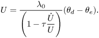 \begin{equation} U = \frac{\lambda_0}{\left(1 - \tau\dfrac{\dot{U}}{U}\right)} (\theta_d - \theta_e). \end{equation}
Comparing this relation with the original form of Hocking's linear relation, the generalized capillary coefficient is expressed as
 \begin{equation} \lambda = \frac{\lambda_0}{\left(1 - \tau\dfrac{\dot{U}}{U}\right)} = \frac{\lambda_0}{1 - \tau\dot{(\ln{U})}}. \end{equation}
For sinusoidal contact line movement, if  $U = U_0{\rm e}^{{\rm i}\omega t}$, we can derive
 \begin{equation} \lambda = \lambda_0(1 + {\rm i}\omega\tau). \end{equation}
This aligns with the prediction by Miles (Reference Miles1990), indicating that the coefficient  $\lambda$ in Hocking's linear law is a complex function of the frequency
 $\omega$.
4.2. Retardation predicted by modified GNBC
The boundary condition for a moving contact line typically involves the Navier boundary condition to remove stress singularity, along with a constitutive relation that defines the contact angle variation with velocity. Constitutive relations, predicted by various theories such as the Cox–Voinov law (Voinov Reference Voinov1977; Cox Reference Cox1986), MKT-based model (Blake Reference Blake2006) or empirical relation like Kistler model (Hoffman Reference Hoffman1975), consistently involve only two variables – angle and velocity. However, the absence of the time derivative of either variable in these relations results in a prediction that the contact angle variation is always in phase with the contact line velocity. Consequently, these relations are not suitable for capturing oscillatory contact line motion.
However, the GNBC, which serve as an alternative to the conventional contact line boundary condition, implicitly includes the time derivative of contact angle  $\dot {\theta }_d$ in the shear term. This feature should result in a phase difference between the contact angle and the contact line velocity, giving rise to dynamic hysteresis. The GNBC describes that in the immediate vicinity of the contact line, the relative velocity of the contact line is proportional to the summation of tangential stresses, encompassing the viscous shear stress and the unbalanced Young's stress (Qian, Wang & Sheng Reference Qian, Wang and Sheng2003). The expression is as follows:
 \begin{equation} \beta U = \tau^V + \tau^Y. \end{equation}
Here, the slip coefficient  $\beta = l_s/\mu$, with
 $l_s$ being the slip length and
 $\mu$ the liquid viscosity. The viscous stress
 $\tau ^V = \mu \partial U/\partial n$, where
 $\partial /\partial n$ denotes the spatial derivative perpendicular to the wall. The integral of the uncompensated Young's stress
 $\tau ^Y$ over the fluid–fluid interfacial region is the unbalanced Young's force (Qian et al. Reference Qian, Wang and Sheng2003):
 \begin{equation} \int_{{interface}} \tau^Y \, {{\rm d}\kern0.7pt x} = \gamma (\cos \theta_e - \cos \theta). \end{equation}
According to the MD simulation, the distribution of  $\tau ^Y$ along the flat substrate (parallel to the
 $x$ direction) is concentrated near the interfacial region, which extends about 10
 $\sigma$ (Qian et al. Reference Qian, Wang and Sheng2003). In MD simulations,
 $\sigma$ represents the range of interaction, typically around a few angstroms for many substances. Based on this, we approximate
 $\tau ^Y$ to be uniformly distributed over a thickness
 $\xi \approx 5\ {\rm nm}$ around the fluid–fluid interface. Thus, the GNBC is given by
 \begin{equation} U = \frac{l_s}{\mu} \left[ \mu \frac{\partial U}{\partial n} + \frac{\gamma}{\xi} (\cos \theta_e - \cos \theta) \right]. \end{equation}
Through a kinematic approach, Fricke, Köhne & Bothe (Reference Fricke, Köhne and Bothe2019) derived that the time derivative of the dynamic contact angle  $\dot {\theta }_d$ can be expressed in terms of the velocity gradient at the solid wall
 ${\partial U}/{\partial n}$. Thus, the relation can be rewritten as
 \begin{equation} U = l_s\dot{\theta}_d + \frac{l_s\gamma}{\xi\mu}\sin{\theta_e}(\theta_d - \theta_e). \end{equation}
To simplify the problem, we model both the contact angle and contact line velocity as sinusoidal signals, expressed as
 $$\begin{gather} \theta_d - \theta_e = \Delta\theta {\rm e}^{{\rm i}\omega t}, \end{gather}$$
 $$\begin{gather}U = U_0{\rm e}^{{\rm i}\omega t}. \end{gather}$$
In these relations only the real part has physical meaning. Substituting these expressions into GNBC:
 \begin{equation} U_0 - {\rm i}l_s\omega\Delta\theta = \frac{l_s\gamma\sin{\theta_e}}{\xi\mu}\Delta\theta. \end{equation}
Thus,
 \begin{equation} \Delta\theta = \frac{U_0}{\dfrac{l_s\gamma}{\xi\mu}\sin{\theta_e} + {\rm i}l_s\omega}. \end{equation}
Multiplying both sides of (4.12) by  $e^{i\omega t}$ and substituting it back into (4.9) gives
 \begin{equation} \theta_d = \theta_e + \frac{U}{\dfrac{l_s\gamma}{\xi\mu}\sin{\theta_e} + {\rm i}l_s\omega} = \theta_e + \frac{U_0\exp\left({{\rm i}\omega \left(t + \dfrac{\alpha}{\omega}\right)}\right) } {\sqrt{\left(\dfrac{l_s\gamma}{\xi\mu}\sin{\theta_e}\right)^2 + (l_s\omega)^2}}, \end{equation}
where  $\tan \alpha = - {\omega }/{({\gamma }/{\xi \mu })\sin {\theta _e}}$. Thus, the retardation time predicted by GNBC is
 \begin{equation} \tau ={-}\frac{\alpha}{\omega} ={-}\frac{1}{\omega}\arctan{\left(-\frac{\omega}{\dfrac{\gamma}{\xi\mu}\sin{\theta_e}}\right)}. \end{equation}
In the above calculation, by utilizing parameter values from our experiment (i.e.  $\omega = 2{\rm \pi} f$,
 $f = 70\ {\rm Hz}$,
 $\gamma = 0.072\ {\rm N}\ {\rm m}^{-1}$, and considering the liquid properties of water:
 $\mu = 0.001\ {\rm Pa}\ {\rm s}$,
 $\sin {\theta _e} = 0.97$) the retardation time
 $\tau$ is calculated to be 0.07 ns.
However, this prediction made by GNBC contradicts experimental observations in two aspects. First, the retardation time predicted by GNBC is much shorter than the experimental results, which is of the order of 0.1 ms, as evidenced in figure 7(b). The second is that surfaces with close wettability ( $\theta _e$), such as PDMS and fluoroalkyl silane, exhibit different retardation times in experiments (see figure 7b). However, this difference, which arises from surface properties other than wettability, cannot be captured by the GNBC prediction. This limitation is evident in (4.14), where only the wettability of the surface is involved.
From this discussion, it is evident that while GNBC can predict a dynamic hysteresis by introducing phase differences between  $\theta$ and
 $U$, the predictions deviate from experimental observations.
The failure identified in GNBC does not negate the potential for predicting dynamic hysteresis using this approach. However, to enhance its predictive capability, we need to incorporate additional surface properties into this relation. Consequently, we modify the GNBC by defining the slip velocity to be proportional to weighted summation of the two tangential stresses, where the weight of the unbalanced Young's stress is inversely proportional to the contact line friction coefficient  $\mu _f$. The modified GNBC is expressed as
 \begin{equation} U = l_s\frac{\partial U}{\partial n} + \frac{\gamma}{\mu_f}(\cos{\theta_e} - \cos{\theta_d}). \end{equation}
Again, rewrite the shear  ${\partial U}/{\partial n}$ as
 $\dot {\theta }_d$:
 \begin{equation} U = l_s\dot{\theta}_d + \frac{\gamma}{\mu_f}(\cos{\theta_e} - \cos{\theta_d}). \end{equation}
Using the same treatment as in the last section, we can derive
 \begin{equation} \theta_d = \theta_e + \frac{U}{\dfrac{\gamma}{\mu_f}\sin{\theta_e} + {\rm i}l_s\omega} = \theta_e + \frac{U_0\exp\left({{\rm i}\omega \left(t + \dfrac{\alpha}{\omega}\right) } \right) }{\sqrt{\left(\dfrac{\gamma}{\mu_f}\sin{\theta_e}\right)^2 + (l_s\omega)^2}}, \end{equation}
where  $\tan \alpha = - {l_s\omega }/{({\gamma }/{\mu _f})\sin {\theta _e}}$. So the retardation time is expressed as
 \begin{equation} \tau ={-}\frac{1}{\omega}\arctan{\left(-\frac{l_s\omega}{\dfrac{\gamma}{\mu_f} \sin{\theta_e}}\right)}. \end{equation}
In (4.18) there are three undetermined parameters:  $\tau$,
 $\mu _f$ and
 $l_s$. By employing the typical values of
 $\tau$ and
 $\mu _f$ obtained from experiment, we can utilize (4.18) to estimate the slip length
 $l_s$:
 \begin{equation} l_s ={-}\tan (-\tau\omega)\frac{\gamma}{\omega\mu_f}\sin{\theta_e}. \end{equation}
Figure 10(b) presents the slip lengths obtained through this approach for the various tested substrates and accelerations. These values are much larger than the slip length typically measured, which is no more than a few hundred nanometres (Leger & Joanny Reference Leger and Joanny1992; Eggers & Stone Reference Eggers and Stone2004; Bhushan, Wang & Maali Reference Bhushan, Wang and Maali2009), yet for now we temporarily treat it as a fitting parameter.
(a) Comparison between the angle–velocity relation obtained from experiment and predicted by modified GNBC. (b) Slip lengths extracted according to the modified GNBC for various substrates and accelerations.

The modified GNBC offers the possibility of defining contact line conditions for oscillatory wetting, enabling more realistic predictions of retardation time with the appropriate selection of slip length and contact line friction coefficient. In figure 10(a) the curve predicted by the modified GNBC is generated by inputting the shifted velocity signal (directly extracted from the experiment)  $U(t - \tau )$ into (4.17) to obtain
 $\theta (t)$, which is then plotted against
 $U(t)$. Despite the hysteresis loop's comparable area to that obtained from the experiment, it is evident from figure 10(a) that when
 $\mu _f$ is treated as a constant, the shape still differs between the prediction and experimental results.
To enhance the predictive accuracy of the modified GNBC, we can further refine the model by considering  $\mu _f$ as a function of the contact angle. This function may resemble that presented in figure 11(c) or given by Amberg (Reference Amberg2022).
However, a notable limitation of this modified GNBC becomes apparent when considering slip lengths across different substrates as derived from this model. Figure 10(b) shows that the most hydrophilic silicon substrates exhibit the largest slip lengths compared with other hydrophobic surfaces. This result contradicts the expected trend where slip length typically increases with hydrophobicity (Huang et al. Reference Huang, Sendner, Horinek, Netz and Bocquet2008; Bhushan et al. Reference Bhushan, Wang and Maali2009). Such discrepancies suggest potential shortcomings in the modified GNBC formulation.
5. Conclusion
The dynamic hysteresis of oscillatory contact line behaviour is experimentally investigated in this work, manifesting as a hysteresis loop in the angle–velocity diagram. Our results underscore the necessity for a constitutive relation tailored to unsteady contact line motion, distinct from that derived under steady conditions. Molecular modifications on the surface induce variations in surface properties beyond wettability. A comparative analysis of oscillatory contact line dynamics on surfaces grafted with PDMS, fluoroalkyl silane, alkyl silane and a bare silicon chip for reference reveals distinct dynamic hysteresis patterns, attributed to differing static hysteresis of the surface.
In addition, by attributing the total mechanical work done by the unbalanced Young's force to contact line frictional dissipation, we can evaluate the contact line friction coefficient through both integrated and discrete forms, capturing both overall magnitude and instantaneous variations. The results indicate an absence of noticeable correlation between dynamic hysteresis and the contact line friction coefficient, suggesting that the observed hysteresis loop is not a result of dissipative effects.
To establish suitable boundary conditions for modelling oscillatory contact line behaviour, we generalized Hocking's linear law by incorporating the capillary coefficient  $\lambda$ as a function of the time derivative of the logarithm of contact line velocity. For a sinusoidal motion, this expression simplifies into a complex function of frequency
 $\omega$, validating Miles's idea (Miles Reference Miles1990). Additionally, we assessed the applicability of GNBC and its modified counterpart during oscillatory wetting. While GNBC generated dynamic hysteresis due to the shear term, the predictions proved unrealistic. In contrast, with a proper choice of slip length and contact line friction coefficient, the modified GNBC can predict dynamic hysteresis in an acceptable way.
This study underscores the intricate interplay of dynamic forces and material properties governing oscillatory wetting behaviour, paving the way for further exploration and refinement of models describing dynamic wetting phenomena.
Supplementary material and movie
Supplementary material and movie are available at https://doi.org/10.1017/jfm.2024.1040.
Acknowledgements
We extend our appreciation to Professor S. Takagi and Dr T. Mouterde for their invaluable discussions and kind support in the development of this work. Additionally, we express our gratitude to M. Pellegrino for having an insightful discussion.
Funding
This work was partially supported by Japan Society for the Promotion of Science (JSPS) (J.S., grant number 22H04950). J.S. gratefully acknowledges support by SPRING GX project.
Declaration of interests
The authors report no conflict of interest.
Appendix A. Discrete form of contact line friction coefficient
Figure 11(a) depicts the temporal evolution of the discrete  $\mu _{f,i}$. Notably, figure 11(b) reveals a discernible elevation in the contact line friction coefficient as the contact line approaches the positions of maximum displacement, marking the stick-slip region. In figure 11(c) the correlation between
 $\mu _f$ and
 $\theta _d$ is illustrated. It is noteworthy that, during variations in the contact angle near its equilibrium value,
 $\mu _{f,i}$ exhibits higher values, thereby substantiating the applicability of the
 $\mu _f$ model proposed by Amberg (Reference Amberg2022) as a function of contact angle. In addition, the plot in panel (d) of figure 11 demonstrates the velocity dependency of the dynamic contact line friction coefficient,
 $\mu _{f,i}$: when the contact line transiently approaches zero speed,
 $\mu _{f,i}$ increases exponentially, indicating a slip-to-stick transition.
Discrete  $\mu _f$ distributed with (a) time, (b) contact line displacement, (c) contact angle, (d) contact line velocity.

Appendix B. The physical interpretation of the experimental contact line friction coefficient
The physical interpretation of the experimentally derived contact line friction coefficient merits attention. As noted in the introduction, the dynamic variation of the macroscopic angle arises from diverse contributions across various scales. The hydrodynamic model addresses viscous friction but overlooks the velocity dependence of the microscopic angle caused by molecular resistance. In contrast, the MKT-based model neglects viscous dissipation while focusing solely on local friction near the contact line at the molecular scale. The  $\mu _f$ extracted in our experiment is more likely a collection of both dissipative effects.
The hydrodynamic model expresses the velocity dependence of viscous bending as (Voinov Reference Voinov1977)
 \begin{equation} g(\theta) - g(\theta_m) = Ca\ln\left(\frac{L}{L_m}\right), \end{equation}
where  $\theta _m$ and
 $L_m$ represent the angle and length scale of the microscopic inner region. The model, however, is unable to determine whether
 $\theta _m$ and
 $L_m$ vary with velocity. On the other hand, the MKT-based model proposes that the microscopic angle
 $\theta _m$ directly depends on velocity due to contact line friction from molecular jumping activities. However, this MKT-based model neglects viscous bending, resulting in the macroscopic angle equating to the microscopic angle and becoming velocity dependent (Blake Reference Blake2006).
The experimentally observed variation in the macroscopic angle may encompass effects from both scales, as indicated by a model combining molecular dissipation and viscous resistance (Brochard-Wyart & De Gennes Reference Brochard-Wyart and De Gennes1992; Blake Reference Blake2006):
 \begin{equation} \gamma(\cos{\theta_e} - \cos{\theta_d})U = \frac{6\mu}{\theta_d}\ln{\frac{L}{L_m}}U^2 + \xi U^2. \end{equation}
Here,  $\xi$ represents the coefficient of wetting-line friction interpretated on the molecular scale. Consequently, the experimentally calculated friction coefficient
 $\mu _f$ can be expressed as the sum of the two components:
 \begin{equation} \mu_f = \frac{6\mu}{\theta_d}\ln{\frac{L}{L_m}} + \xi. \end{equation}
Recently, the tapping mode AFM technique has unveiled convex nanobending as a crucial link between molecular-scale and mesoscopic-scale angles (Chen et al. Reference Chen, Yu and Wang2014; Wang Reference Wang2019; Liu, Yu & Wang Reference Liu, Yu and Wang2020). Chen et al. (Reference Chen, Yu and Wang2014) observed that nanobending exhibits velocity dependence. This discovery implies that the experimentally assessed friction coefficient  $\mu _f$ should incorporate additional components beyond the right-hand side of (B3) to accommodate the contribution from nanobending.
Once again, we emphasize that using a constitutive relation between the dynamic contact angle and contact line speed is one way to describe dynamic contact line behaviour. In this approach, the effective contact line friction coefficient is introduced to linearize and simplify the relation. However, other approaches, such as highly resolved DNS based purely on a hydrodynamic perspective without considering the velocity dependence of the microscopic angle, can also successfully describe dynamic wetting phenomena in complex systems like curtain coating.


 Open access

