1 Introduction
Patterning of droplets in structured arrays is of paramount importance, considering its fundamental implications in understanding the science of melting and evaporation, as well as diverse applications ranging from photonics and near field imaging, lubrication, water-repellent coatings, inkjet printing, cellular and tissue level analysis, DNA sequencing, high throughput screening and digital polymerase chain reaction (PCR), to name a few (K.Tang Reference K.Tang1994; Calvert Reference Calvert2001; Brutin et al. Reference Brutin, Sobac, Loquet and Sampol2011; Cerf et al. Reference Cerf, Alava, Barton and Craighead2011; Pinheiro et al. Reference Pinheiro, Coleman, Hindson and Emslie2012; Style et al. Reference Style, Che, Park, Weon, Je, Hyland, German, Power, Wilen, Wettlaufer and Dufresne2013; Boreyko et al. Reference Boreyko, Hansen, Murphy, Nath, Retterer and Collier2016; Tian et al. Reference Tian, Martin, Bassindale and Mann2016).
In practical scenarios, the specific design of droplet arrays is governed by the demands of resolution, throughput of processing and detection sensitivity. However, the dynamics of evaporation works as a fundamental scientific guideline towards dictating the underlying functionalities. While evaporation dynamics of a single surface droplet has been extensively studied (Picknett & Bexon Reference Picknett and Bexon1977; Hu & Larson Reference Hu and Larson2002, Reference Hu and Larson2005; Chen et al.
Reference Chen, Ma, Li and Wang2012; Nguyen et al.
Reference Nguyen, Nguyen, Hampton, Xu, Huang and Rudolph2012), insights into the collective dynamics of a structured array of surface droplets remain elusive. This deficit stems from the complexities in elucidating the role of an altered concentration gradient by saturating the solvent in between neighbouring droplets, as a consequence of vapour-mediated intricate interactions. In practice, the extent of these vapour-mediated interactions depends on the relative spacing between the individual droplets. Previous studies involved approaches such as experiments, numerical simulations and statistical correlations to decode the evaporation dynamics of an interacting droplet system. In particular, Laghezza et al. (Reference Laghezza, Dietrich, Yeomans and Lohse2016) have explored the collective and convective effects of surrounding droplets on the evaporation dynamics of a droplet placed at the geometric centre of the array. Their observation of an approximate maximum 60 % increase in evaporation lifetime is well supported by the simulations considering three-dimensional diffusion effects. Jyoti, Shaikeea & Basu (Reference Jyoti, Shaikeea and Basu2016), based on the experimental evidence have correlated the increase in lifetime of an interacting two droplet system with the corresponding droplet–droplet separation distances. Bansal et al. (Reference Bansal, Hatte, Basu and Chakraborty2017) and Hatte et al. (Reference Hatte, Dhar, Bansal, Chakraborty and Basu2019) have characterised the alterations in the evaporation dynamics of a single sessile droplet trapped in an open rectangular channel. Their scaling argument based on vapour confinement due to channel walls predicts the consequent increase in evaporation lifetime for a range of channel dimensions. Carrier, Shahidzadeh-bonn & Zargar (Reference Carrier, Shahidzadeh-bonn and Zargar2016) developed a semi-analytical model to predict the evaporation rate of a collection of interacting sessile droplets. They assumed that the system of
 $n$
-droplets collectively behaves as a super-drop of radius
 $R_{S}$
. Subsequently, Carrier et al. (Reference Carrier, Shahidzadeh-bonn and Zargar2016) divided the problem into two domains, inner and outer. They finally solved for inner and outer region solutions semi-analytically with appropriate boundary conditions to obtain the evaporation lifetime scaling.
Despite the above advancements, there are certain limitations associated with the aforementioned studies. For example, Laghezza et al. (Reference Laghezza, Dietrich, Yeomans and Lohse2016) do not stress the functional dependence of droplet separation values on the evaporation lifetime scaling of centrally placed droplet. The study of Jyoti et al. (Reference Jyoti, Shaikeea and Basu2016) on an interacting two-droplet system does not mention the possible extension of their model to a generalised array of sessile droplets. Also, Bansal et al. (Reference Bansal, Hatte, Basu and Chakraborty2017) and Hatte et al. (Reference Hatte, Dhar, Bansal, Chakraborty and Basu2019) did not explore the extension of their model for different forms of geometric confinements (droplet surrounded by droplet(s)). The basic assumption of modelling the collection of droplets as a single flat super-drop, as adopted by Carrier et al. (Reference Carrier, Shahidzadeh-bonn and Zargar2016), fails for sufficiently large separations among the individual droplets. There exists no elegant theoretical model that can predict the evaporation lifetime scaling of an interacting droplet arrays. In addition, the aforementioned studies fail to reproduce theoretical evidence for two critical limiting scenarios; first, droplet separation distances beyond a threshold limit for which vapour-mediated interactions cease to exist and second, for extremely low separation values (droplets on the verge of coalescence) for which the centre droplet approaches a maximum limit in evaporation lifetime. Additionally, all the past studies never really delve into the rich flow physics that is created due to the spatio-temporal changes in evaporation patterns. Such flow patterns can be harnessed and utilised in countless applications across multiple domains like surface patterning, biomedical engineering, self-assembly to name a few. In summary, there is a deficit in the literature in comprehending the evaporation dynamics and universal evaporative lifetime of any one-dimensional generic array of interacting droplets.
Here, we first decode the evaporation dynamics of a system of three droplets resting in close vicinity of each other in a linear arrangement on a hydrophobic substrate. It is to be noted that the three-droplet system forms a fundamental unit that mimics the evaporation dynamics of any closely placed
 $n$
-droplet array
 $(n\geqslant 3)$
. We show that local evaporation characteristics, such as contact line motion and internal flow dynamics of an interacting three-droplet system, show significant deviation from its isolated single droplet counterpart for a range of droplet spacing values. We propose a novel scaling approach from simple theoretical arguments that can accurately predict the evaporation lifetime of any centrally placed droplet in a linear array irrespective of the separation distance. We also show that two extreme bounds of three-droplet system behaviour can be envisaged. First, beyond critical droplet spacing, the three-droplet system behaves as a set of three individual isolated droplets with insignificant interactions among them. Second, for a minimum spacing of zero (droplets on the verge of coalescence), there exists a maximum limit on the evaporation lifetime. Lastly, repeated experiments on a four-droplet system and asymmetric placement of the centre droplet showed excellent agreement with the scaling theory proposed for the drop lifetime. Hence, our hypothesis of an interacting three-droplet system mimicking an
 $n$
-droplet array
 $(n\geqslant 3)$
is now extended for any combinations of relative positions of individual droplets, bearing far-reaching consequences in diverse applications ranging from bio-molecular analysis to photonic manipulation on a substrate. Additionally, we also establish perfect analogy with other forms of droplet confinement, such as a droplet trapped in a rectangular channel. We also showcase the alteration in internal flow patterns attributed to droplet–droplet vapour-mediated interactions.
Schematic of droplet-based systems. (a) Schematic depicting several applications such as DNA chip preparations, inkjet printing etc. utilising two-dimensional arrays of sessile droplets. (b) A linear array of
 $n$
-sessile droplets
 $(n\geqslant 3)$
placed in close vicinity to each other, and (c) an interacting three-droplet system where CD is kept equidistant (at a separation of
 $L$
) from both SDs. CD and SD denote the centre droplet and side droplet respectively.

2 Materials and methods
A vertical syringe pump assembly is used to deploy three
 $2~\unicode[STIX]{x03BC}\text{l}$
volume droplets (figure 1) of deionised water on a substrate. Primarily, experiments are conducted on polydimethylsiloxane (PDMS) substrate. In addition, two other substrates namely, glass and silicon are also considered to verify the consistency of the present model for a variety of droplet–substrate combinations. PDMS substrates are prepared by spin-coating glass slides with PDMS Slygard 184 (Dow Corning, Wiesbaden, Germany) solution in 10 : 1 weight ratio and curing them at approximately
 $90\,^{\circ }\text{C}$
for 4–5 h. Glass and silicon substrates are procured from a local supplier and cleaned thoroughly in an ultrasonic bath of acetone, methanol and deionised water (in the given order). Subsequently, the substrates are dried in a vacuum oven and used for experimental runs. A horizontal gear enabled movable stage is used for maintaining a specific distance between the neighbouring droplets in a perfectly linear arrangement. Delay in deploying the first and third droplets is approximately 1 min which is insignificant compared to the lifetime (
 ${>}15$
min) of the interacting three-droplet system. Changes in the morphology of the droplets, mainly their contact radius and contact angle, are captured at 1 f.p.s. by shawdography technique using a Nikon digital SLR 7200 camera fitted with Navitar zoom lens assembly. For internal flow field visualisation, the working fluid is seeded with rhodamine coated polystyrene particles (Thermo Fisher Scientific) of diameter 860 nm in low concentrations of 0.008 %vol. To stabilise the flow field pattern glycerol is added in dilute concentration (
 ${\sim}6\,\%$
by vol.), such that the relevant physico-chemical properties of the working fluid that govern the evaporation dynamics (surface tension, effective exposed surface area and static contact angle) do not change (Mallinson, Mcbain & Horrocks Reference Mallinson, Mcbain and Horrocks2016). Internal flow patterns are observed by two different ways. For side view visualisation, a vertical laser sheet (cobalt-samba laser (wavelength, 532 nm)) of
 $160~\unicode[STIX]{x03BC}\text{m}$
thickness is passed through centres of the three droplets, and images are obtained at 5 f.p.s. using a Nikon digital SLR 7200 camera fitted with a Navitar zoom lens. For the bottom view, particle image velocimetry (PIV), images are obtained at 5 f.p.s. by an Imager Intense (Lavision) camera fitted on a Flowmaster Mitas microscope. Bottom view images are obtained in a plane at half of the droplet height. The entire experimental set-up is enclosed to limit the convective effects. It is ensured that the enclosure walls are sufficiently distant, such that they do not exhibit vapour-mediated interaction with the evaporating droplet system. Ambient conditions are maintained at a temperature of
 $25\pm 1\,^{\circ }\text{C}$
and RH (relative humidity) of
 $40\pm 5\,\%$
. All the evaporation lifetime measurements and PIV readings are repeated 5 times for each configuration (each set of droplet separation values) for statistical consistency.
3 Results
An array of sessile droplets placed in close proximity serves as a framework for many industrial applications (Calvert Reference Calvert2001; Gans & Schubert Reference Gans and Schubert2003; Song, Chen & Ismagilov Reference Song, Chen and Ismagilov2006; Cerf et al.
Reference Cerf, Alava, Barton and Craighead2011; Boreyko et al.
Reference Boreyko, Hansen, Murphy, Nath, Retterer and Collier2016). Such linear
 $n$
-droplet
 $(n\geqslant 3)$
arrays are categorised into two types; first, edge droplets, with only one neighbouring sessile droplet (figure 1
b), and second, the centre droplet always flanked by two neighbours as shown in figure 1(b). Figure 1(c) depicts that the CD (centre droplet) is accompanied by two SDs (side droplets) at separations of
 $L1$
and
 $L2$
. For most of this study, the droplet separation values are equal (
 $L1=L2=L$
) unless specified otherwise. The extent of proximity of the droplets in this configuration results in distinct evaporation dynamics (compared to its isolated droplet counterpart) because of the interactions mediated through the diffusion of vapour from the liquid–air interface. Hence, the droplet separation length (
 $L$
) plays an important role in characterising the distinct behaviour of
 $n$
-droplet arrays. First, there exists a minimum critical separation length (
 $L_{cr}$
; discussed later) above which
 $(L>L_{cr})$
the
 $n$
-droplet array behaves as ‘
 $n$
’ individual droplets without any interaction. Second, for a range of separation lengths
 $(L<L_{cr})$
, the extent of droplet–droplet interaction depends on the absolute values of
 $L$
and
 $D_{e}$
(droplet equatorial diameter). In the subsequent sections, the evaporation dynamics, namely, contact line dynamics, internal flow patterns and total vaporisation time scales are discussed for CD and SD in comparison to their isolated droplet counterparts.
Schematic depiction of evaporation flux distribution for a system of hydrophilic and hydrophobic droplet(s). Front view shows the variation of evaporation flux along the polar direction for (a) an isolated hydrophobic droplet, (b) interacting hydrophobic three-droplet system, (c) an isolated hydrophilic droplet and (d) an interacting hydrophilic three-droplet system. Top view shows the evaporation flux distribution along the azimuthal direction for (c) an isolated droplet, and (d) an interacting three-droplet system valid for both hydrophilic and hydrophobic droplet(s). Red dash-dot lines represent the axes of symmetry for evaporation flux distribution. Shaded green region in (b) depicts the region of suppressed evaporation flux due to wedge formation, while the shaded orange region depicts the vapour confinement due to droplet–droplet interaction.

4 Isolated single droplet: a control study
The distribution of evaporation flux
 $(J(\unicode[STIX]{x1D703},\unicode[STIX]{x1D711}))$
around a sessile droplet is a function of its shape alone (Deegan et al.
Reference Deegan, Bakajin, Dupont, Huber, Nagel and Witten1997). For a sessile droplet evaporating on a hydrophobic substrate, the evaporation flux distribution is symmetric along the azimuthal direction
 $(\unicode[STIX]{x2202}J/\unicode[STIX]{x2202}\unicode[STIX]{x1D711}\approx 0)$
; however, it varies along the polar direction
 $(\unicode[STIX]{x2202}J/\unicode[STIX]{x2202}\unicode[STIX]{x1D703}\neq 0)$
as depicted in figure 2. For a sessile droplet on a hydrophilic substrate, the evaporation flux is maximum at the three phase contact line
 $(\unicode[STIX]{x1D703}=0)$
, while it is minimum at the apex region
 $(\unicode[STIX]{x1D703}=\unicode[STIX]{x03C0}/2)$
(Deegan et al.
Reference Deegan, Bakajin, Dupont, Huber, Nagel and Witten1997). However, for a hydrophobic sessile droplet, a wedge-like region of enhanced vapour concentration reduces the evaporation flux near the three phase contact line. Therefore, for a hydrophobic sessile droplet, evaporation flux is maximum at the apex point
 $(\unicode[STIX]{x1D703}=\unicode[STIX]{x03C0}/2)$
and minimum at the three phase droplet contact line
 $(\unicode[STIX]{x1D703}=0)$
(Jyoti et al.
Reference Jyoti, Shaikeea and Basu2016). Evaporation rate and flux distribution govern the contact line dynamics and internal flow features (strength and pattern). Based on transient contact line dynamics, there exist two distinct modes of evaporation, namely, CCR (constant contact radius) and CCA (constant contact angle) (Nguyen & Nguyen Reference Nguyen and Nguyen2012; Yu, Wang & Zhao Reference Yu, Wang and Zhao2012; Jyoti et al.
Reference Jyoti, Shaikeea, Basu and Bansal2017). In addition, numerous studies have reported a mixed mode of evaporation where both contact radius and contact angle undergo simultaneous changes (Nguyen & Nguyen Reference Nguyen and Nguyen2012). In general, CCR and CCA modes of evaporation are tools to characterise the wettability of the surface. For example, sessile droplets evaporating on super-hydrophilic surfaces generally show pinned contact line behaviour resulting in the CCR mode of evaporation with high contact angle hysteresis. On the other hand, superhydrophobic surfaces generally support the CCA mode of droplet evaporation with negligible contact angle hysteresis. In the present case (control study), an isolated sessile droplet (ID) on a PDMS substrate shows an initial contact angle of
 $110^{\circ }\pm 2^{\circ }$
, with an overall standard deviation of 6 %. The ID evaporating on a PDMS substrate shows a buoyancy-driven double toroid flow pattern. Figure 4(a,d) shows the side and bottom view PIV flow field. The bottom view vector field indicates an average velocity
 ${\sim}6{-}8~\unicode[STIX]{x03BC}\text{m}~\text{sec}^{-1}$
(at around
 $t/t_{e,ID}\approx 0.1$
). Glass substrate and silicon wafer offer an initial contact angle of
 $45^{\circ }\pm 3^{\circ }$
and
 $72^{\circ }\pm 3^{\circ }$
respectively. Internal flow fields of sessile droplets resting on such hydrophilic substrates show the traditional radially outward capillary flow (as seen in the coffee ring effect) (Deegan et al.
Reference Deegan, Bakajin, Dupont, Huber, Nagel and Witten1997).
Apart from the local dynamics such as contact line movement and the internal flow field, global parameters such as total evaporation time scales form an important aspect of sessile droplet evaporation. For a diffusion-based evaporation model (negligible external convective effects), the rate of droplet volume change is given by Fick’s law (Jyoti et al. Reference Jyoti, Shaikeea and Basu2016; Bansal et al. Reference Bansal, Hatte, Basu and Chakraborty2017; Hatte et al. Reference Hatte, Dhar, Bansal, Chakraborty and Basu2019):
 $$\begin{eqnarray}\frac{\text{d}V}{\text{d}t}=\frac{-J_{avg}A_{d}}{\unicode[STIX]{x1D70C}}=\frac{-2\unicode[STIX]{x03C0}DMR_{c}\,f(\unicode[STIX]{x1D703}_{c})(c_{s}-c_{\infty })}{\unicode[STIX]{x1D70C}},\end{eqnarray}$$
where,
 $V$
is the instantaneous droplet volume,
 $J_{avg}$
is the global evaporation flux value averaged around the droplet surface,
 $A_{d}$
is the instantaneous droplet surface area,
 $\unicode[STIX]{x1D70C}$
is the density of working fluid,
 $D$
is the diffusion constant of vapour in air,
 $R_{c}$
and
 $\unicode[STIX]{x1D703}_{c}$
are the instantaneous droplet contact radius and contact angle respectively and
 $C_{s}$
and
 $C_{\infty }$
are the vapour concentrations near and far away from the interface respectively. For
 $\unicode[STIX]{x1D703}_{c}>10^{\circ }$
,
 $f(\unicode[STIX]{x1D703}_{c})=(0.00008957+0.633\unicode[STIX]{x1D703}_{c}+0.116\unicode[STIX]{x1D703}_{c}^{2}-0.08878\unicode[STIX]{x1D703}_{c}^{3}+0.01033\unicode[STIX]{x1D703}_{c}^{4})/\text{sin}(\unicode[STIX]{x1D703}_{c})$
(Picknett & Bexon Reference Picknett and Bexon1977);
 $f(\unicode[STIX]{x1D703}_{c})$
is a geometric factor that takes into account the incomplete spherical shape of a sessile droplet. Instantaneous contact line parameters (
 $R_{c}$
and
 $\unicode[STIX]{x1D703}_{c}$
) strongly affect the vaporisation time scales. In the present case, the average evaporation rate is represented in terms of its initial contact line parameters (discussed later). The basic assumption underlying (4.1) is the presence of uniform infinite medium for the diffusion of vapour. However, this assumption is not valid in practical cases where vapour diffusing out from the liquid–air interface experiences reduced mobility.
5 An interacting linear three-droplet system
An evaporating sessile droplet interacts with its surrounding entities. In diffusion-based systems, these interactions are mediated through the vapour field. For an interacting hydrophobic three-droplet system, a wedge-like confinement forms naturally between the CD and SD (figure 2). Due to the close proximity of the droplets, an additional region of vapour confinement is formed (figure 2). For the case of an interacting three-droplet system over a hydrophilic substrate, due to the absence of a wedge-like confinement region, it is only the proximity of neighbouring droplets that gives rise to the formation of the vapour confinement zone, as depicted in figure 2. We will show in subsequent sections that the present model is valid for both hydrophilic and hydrophobic droplet systems. The dimensions of this vapour confinement space depend strongly on the separation distance between CD and SD. The wedge leads to reduced mobility (diminished tendency to diffuse out to the ambient) forcing the vapour to accumulate in the confinement resulting in relatively enhanced local vapour concentration
 $c_{\infty }^{\prime }(c_{\infty }<c_{\infty }^{\prime }<c_{s})$
. Hence, the extent of vapour-mediated interactions depends on the geometric parameters that create the region of confinement in the first place. The spatial variation of vapour concentration for CD and SD results in the redistribution of evaporation flux pattern as shown in figure 2 (compared to the isolated droplet counterpart). Figure 2(b,d) shows that for SD, the liquid–air interface close to the wedge shows relative suppression of the evaporation flux. CD however suffers an overall degradation in evaporation rate as well as strong spatial variations in both azimuthal and polar directions. In the subsequent sections, vapour-mediated interaction induced effects on the evaporation dynamics of a three-droplet system is studied for a range of droplet separation values
 $(L/D_{e}\in [1.1,2.6])$
. We will focus on the details pertaining to a PDMS substrate unless stated otherwise. However, we will show that the evaporation lifetime scaling is equally applicable to other substrates as well.
CD contact line dynamics. Transient variation of (a) contact radius (b) contact angle and (c) droplet volume for different cases of droplet separation values. Inadequacy of the normalising time scale is evident in all the plots.

6 Contact line dynamics
In the current set of experiments, the sessile droplets can be approximated as a spherical cap since the contact radius of 0.75 mm (for
 $2~\unicode[STIX]{x03BC}\text{l}$
volume) is much lower than the corresponding capillary length;
 $\sqrt{\unicode[STIX]{x1D70E}/\unicode[STIX]{x1D70C}g}\approx 2.7$
mm. Initial contact radius and contact angle of a sessile droplet are dependent on the wettability of the substrate. However, with progressive evaporation, the dynamics is characterised by the transient variation in droplet contact line parameters; contact radius (
 $R_{c}$
) and contact angle (
 $\unicode[STIX]{x1D703}_{c}$
). For all values of SD–CD separation (
 $L$
) considered in the experiments, the range of droplet contact radius (PDMS substrate) is observed as: initial contact radius
 ${\sim}0.75$
mm; final contact radius
 ${\sim}0.48$
mm. Assuming a spherical cap geometry, the transient variation of droplet volume is shown in figure 3(c). There are two important observations from the volume regression plot (figure 3
c). First, the variation of droplet volume is nonlinear in nature. It is well known that the initial linearity in droplet volume regression is lost due to the inherent slip of the contact line (Bansal et al.
Reference Bansal, Hatte, Basu and Chakraborty2017; Hatte et al.
Reference Hatte, Dhar, Bansal, Chakraborty and Basu2019). Second, the evaporation lifetime is significantly different for different values of droplet spacing (
 $L/D_{e}$
). In the present study, a maximum of 65 % increase in evaporation lifetime (compared to ID) is observed for a droplet spacing of
 $L/D_{e}\approx 1.1$
. It is tempting to scale the evaporative lifetime of a three-droplet system with that of the single droplet (ID), as shown in figure 3. However, this scaling causes significant divergence in contact line parameters for different
 $L/D$
ratios. This consequently proves the inadequacy of the time scale involving ID. Hence, for an interacting three-droplet system, a different time scale is necessary which ideally should unify the transient data (contact line parameters, volume) across all
 $L/D$
values.
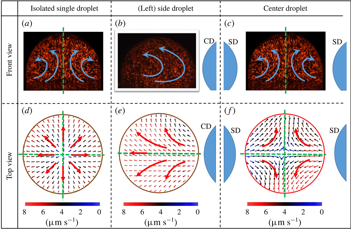
Internal flow dynamics. Flow field visualisation from front view for (a) an isolated sessile droplet (b) CD, (c) SD and flow vector characterisation from bottom view for (d) an isolated sessile droplet (e) CD and (f) SD. Droplet separation value of
 $L/D_{e}=1$
is considered for symmetric interacting three-droplet system. Arrows denote the direction of internal flow and green dotted lines indicate the axes of symmetry.

7 Internal flow dynamics
Evaporation flux distribution around a sessile droplet governs its internal flow dynamics as discussed in the previous section. The same is evident from the equal number of axes of symmetries in evaporation flux distributions (figure 2) and corresponding internal flow fields (figure 4). As a result, for an interacting three-droplet system, vapour-mediated interaction induced redistribution of the evaporation flux causes alterations in the internal flow patterns of CD and SD (compared to its ID counterpart). In the present case, internal flow dynamics of CD and SD is studied for two cases; first, for lower value of droplet separation
 $L/D_{e}\approx 1$
, and symmetric placement of CD; second, for an asymmetric placement of CD.
For a CD, in symmetric three-droplet system, the presence of two SDs at opposite ends affects the evaporation flux distribution as represented in figure 2(b,d,f). As a result, the bottom view flow field appears to be originating from the region of high vapour confinement and directed towards the relatively relaxed region at ambient conditions (figure 4
f). It is interesting to note that the side view flow field exhibiting a double toroid flow pattern is similar to its ID counterpart (with two axes of symmetry) because of the symmetric placement of CD (figure 4
a,c). However, due to a suppressed evaporation flux, the magnitude of the internal flow field for CD (
 $3.5~\unicode[STIX]{x03BC}\text{m}~\text{s}^{-1}$
) is lower than the corresponding ID (
 ${\sim}7~\unicode[STIX]{x03BC}\text{m}~\text{s}^{-1}$
). For a SD, there exists a highly asymmetric evaporation flux distribution (figure 2
b,d) mainly due to preferential vapour accumulation on one side and ambient conditions on the other. As a result, a unidirectional flow field is observed from bottom view particle image velocimetry (PIV), as shown in figure 4(e), as opposed to a divergent flow as encountered in ID (isolated droplet). The flow is essentially directed towards the droplet side that is exposed to the ambient (zone of relaxed concentration). In addition, from figure 4(b), it is observed that the side view PIV flow field for SD shows a transition from double toroid (ID counterpart) to a single toroid flow pattern directed away from CD. SD flow field with progression in evaporation develops a pair of vortices on the side facing the CD as shown in figure 5(c). The formation of vortices is attributed to restoration of the SD flow field from unidirectional to the divergent double toroidal flow pattern (bottom view PIV for ID). However, with progressive evaporation, as the dynamic separation between the SD and CD increases, the initial vapour field is relaxed, thereby restoring the symmetric distribution of evaporation flux for SD. As a result, during the later part of the evaporation lifetime
 $(t/t_{e}\approx 0.8)$
, the SD flow field transitions from a single toroid to double toroid flow field exhibiting a pair of transient intermediate vortical structures. The same pair of vortices are observed from the side view PIV of SD at a plane perpendicular to the line joining the three droplets as shown in figure 5(d). These vortical structures are repeatable across all experimental realisations. Further, at sufficiently higher values of droplet spacing
 $L/D_{e}>2.6$
, internal flow field patterns of CD and SD in a three-droplet interacting system are observed to be strikingly similar to an ID. Hence, it is stated that for droplet spacing of
 $L/D_{e}>2.6$
, the three-droplet system shows insignificant vapour-mediated interactions and behave as three individual IDs. Mathematical reasoning for this critical/threshold magnitude
 $(L/D_{e}>2.6)$
is explained in following section.
Bottom view flow field of an interacting three -droplet system. Bottom view flow field of (left) SD for a symmetric placement of CD at (a)
 $(t/t_{e}\approx 0.1)$
, (b)
 $(t/t_{e}\approx 0.5)$
, (c)
 $(t/t_{e}\approx 0.8)$
and (d) side view flow field in a plane perpendicular to the line joining the three linear droplets. (c) Shows formation of vortices near the end of the evaporation lifetime. Bottom view flow field of CD for extreme levels of asymmetric placement of CD, (e)
 $L1/D=1.7$
,
 $L2/D=3.4$
and (f)
 $L1/D=1.7$
,
 $L2/D=8.5$
. Smaller circular objects represent the position of CD and/or SD to highlight the position of the droplet under observation.

For an asymmetric droplet system (the CD is not equidistant from the two SDs), the internal flow field in the CD differs significantly from the case of a symmetric droplet system. Relatively higher vapour accumulation on one side compared to the other results in a unidirectional flow field as observed from the bottom view PIV flow field (figure 5
e,f) for two asymmetric configurations. In both cases (figure 5
e,f), the relative separations (
 $L2/L1$
) are varied from 2 to 5. The flow field pattern remain sufficiently similar.
8 Droplet lifetime scaling
Figure 3(c) shows that the lifetime of CD from the interacting three-droplet system is higher than its ID counterpart. In addition, figure 3 also shows that the correct scaling of CD lifetime should incorporate the relative separation (
 $L/D_{e}$
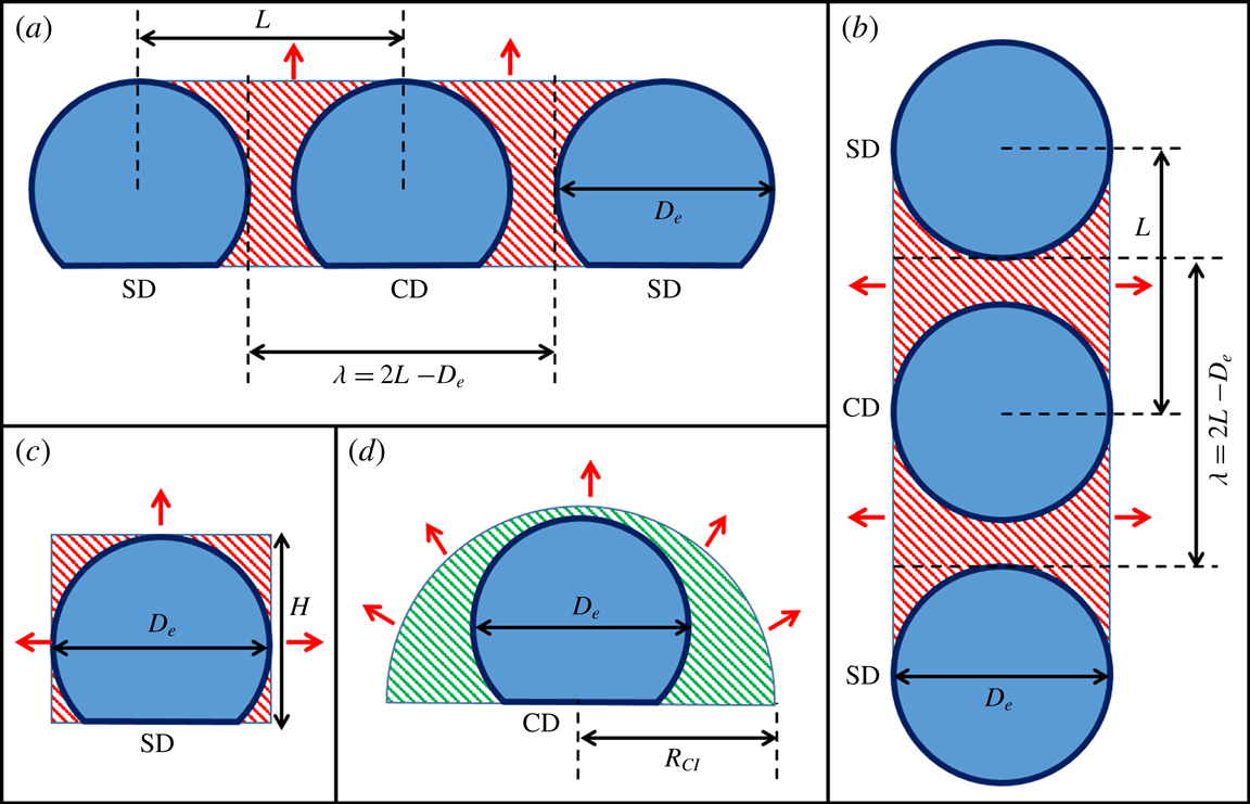
). Figure 6 illustrates the wedge region responsible for the accumulation of vapour thereby slowing down the evaporation process.
Schematic of the region of vapour entrapment with enhanced vapour concentration of
 $c_{\infty }^{\prime }$
. (a) Front view and (b) top view of the cuboid and equivalent half-cylindrical region of vapour entrapment, (c) side view of the cuboidal region of vapour entrapment and (d) side view of the equivalent half-cylindrical region of vapour entrapment. Red arrows denote the direction of vapour front propagation.

In order to develop a mathematically consistent scaling argument, a region of vapour-mediated interaction is first defined. Geometric parameters that define the extent and region of vapour confinement are – droplet spacing (
 $L$
), droplet contact radius (
 $R_{c}$
), droplet equatorial diameter (
 $D_{e}$
), droplet height (
 $H$
) and contact angle (
 $\unicode[STIX]{x1D703}_{c}$
). Along the direction of droplet placement, the CD vapour field is obstructed by the presence of two SDs each at spacing
 $L$
. In order to establish a mathematical model encompassing the aforementioned geometric parameters, a lumped model is proposed.
We arrive at a simple new unified theory on the evaporating droplet lifetime by replacing the traditionally described single-step process with a two-step diffusion model. The first step physically signifies the fact that vapour leaving the liquid–air interface is accumulated in the region of vapour entrapment, exhibiting an enhanced vapour concentration of
 $c_{\infty }^{\prime }$
(figure 6) in the ambient. Instantaneous rate of droplet volume decay in this step is expressed in terms of its governing parameters as per Fick’s law:
 $$\begin{eqnarray}\frac{\text{d}V}{\text{d}t}=\frac{-2\unicode[STIX]{x03C0}DMR_{c}\,f(\unicode[STIX]{x1D703})(c_{s}-c_{\infty }^{\prime })}{\unicode[STIX]{x1D70C}}.\end{eqnarray}$$
In the second step, it is assumed that the entrapped vapour field diffuses out in a linear fashion to the ambient
 $(c_{\infty })$
over a length scale
 $\overline{La}$
.
 $$\begin{eqnarray}\frac{\text{d}V}{\text{d}t}_{avg}=-\frac{DM(A_{c})(c_{\infty }^{\prime }-c_{\infty })}{\unicode[STIX]{x1D70C}\overline{L_{a}}},\end{eqnarray}$$
where,
 $A_{c}$
is the surface area of the vapour field front (discussed later). These two processes are in equilibrium with very little variation of
 $c_{\infty }^{\prime }$
almost throughout the lifetime of CD. The average rate of droplet volume decay can be cast in terms of its initial geometric parameters:
 $$\begin{eqnarray}\frac{\text{d}V}{\text{d}t}_{avg}=A\frac{-2\unicode[STIX]{x03C0}DMR_{ci}\,f(\unicode[STIX]{x1D703}_{ci})(c_{s}-c_{\infty }^{\prime })}{\unicode[STIX]{x1D70C}},\end{eqnarray}$$
where
 $A$
is a fitting parameter (of the order of unity), with specific value (as fitted from a wide range of experimental data) of approximately 0.74 i.e.
 ${\sim}O(1)$
. Equation (8.3) shows excellent agreement with experimental data (insignificant deviation of 2.7 %). Equating (8.2) and (8.3) we get,
 $$\begin{eqnarray}-\frac{DM(A_{c})(c_{\infty }^{\prime }-c_{\infty })}{\unicode[STIX]{x1D70C}\overline{L_{a}}}=A\frac{-2\unicode[STIX]{x03C0}DMR_{ci}\,f(\unicode[STIX]{x1D703}_{ci})(c_{s}-c_{\infty }^{\prime })}{\unicode[STIX]{x1D70C}}.\end{eqnarray}$$
Rearranging (8.4) we get,
 $$\begin{eqnarray}(c_{\infty }^{\prime }-c_{\infty })=\frac{\overline{L_{a}}}{A_{c}}\times A2\unicode[STIX]{x03C0}R_{ci}\,f(\unicode[STIX]{x1D703}_{ci})(c_{s}-c_{\infty }^{\prime }).\end{eqnarray}$$
From (8.5),
 $c_{\infty }^{\prime }$
is represented in terms of
 $c_{s}$
and
 $c_{\infty }$
as,
 $$\begin{eqnarray}c_{\infty }^{\prime }=\frac{\overline{L_{a}}A2\unicode[STIX]{x03C0}R_{ci}\,f(\unicode[STIX]{x1D703}_{ci})c_{s}+A_{c}c_{\infty }}{(A_{c}+\overline{L_{a}}A2\unicode[STIX]{x03C0}R_{ci}\,f(\unicode[STIX]{x1D703}_{ci}))}.\end{eqnarray}$$
Multiplying (8.6) by
 $-1$
and adding
 $c_{s}$
on both sides we get,
 $$\begin{eqnarray}(c_{S}-c_{\infty }^{\prime })=c_{S}-\frac{\overline{L_{a}}A2\unicode[STIX]{x03C0}R_{ci}\,f(\unicode[STIX]{x1D703}_{ci})c_{s}+A_{c}c_{\infty }}{(A_{c}+\overline{L_{a}}A2\unicode[STIX]{x03C0}R_{ci}\,f(\unicode[STIX]{x1D703}_{ci}))}.\end{eqnarray}$$
Rearranging (8.7) we get
 $(c_{S}-c_{\infty }^{\prime })$
in terms of
 $(c_{s}-c_{\infty })$
as,
 $$\begin{eqnarray}(c_{S}-c_{\infty }^{\prime })=\frac{A_{c}(C_{S}-c_{\infty })}{(A2\unicode[STIX]{x03C0}R_{Ci}\,f(\unicode[STIX]{x1D703}_{ci})\overline{L_{a}}+A_{c})}.\end{eqnarray}$$
Substituting (8.8) in (8.3), and rewriting
 $|(\text{d}V/\text{d}t)_{avg}|\approx V_{d}/t_{e,CD}$
, we get,
 $$\begin{eqnarray}\frac{t_{e,CD}}{V_{d}}=\frac{\overline{L_{a}}}{\unicode[STIX]{x1D6FC}A_{c}}+\frac{1}{\unicode[STIX]{x1D6FC}(2\unicode[STIX]{x03C0}AR_{ci}\,f(\unicode[STIX]{x1D703}_{ci}))},\end{eqnarray}$$
where,
 $t_{e,CD}$
is the lifetime of the CD,
 $V_{d}$
is the initial droplet volume and
 $\unicode[STIX]{x1D6FC}=(2\unicode[STIX]{x03C0}DM(c_{s}-c_{\infty }))/\unicode[STIX]{x1D70C}$
.
Average vapour accumulation length
 $\overline{L_{a}}$
depends on the geometric parameters of the interacting three-droplet system. In order to quantify this dependency, a vapour concentration field along the radially outward direction from the liquid–air interface is simulated for an isolated spherical droplet, as shown in figure 7.
Variation of vapour concentration along the radial direction for a spherical isolated droplet.

The obtained value of
 $\unicode[STIX]{x1D6FD}\sim 4$
, indicates the radial distance
 $(r=\unicode[STIX]{x1D6FD}D_{e})$
at which the vapour concentration gradient is
 ${\sim}0$
(i.e.
 $\unicode[STIX]{x2202}c/\unicode[STIX]{x2202}r|_{r=\unicode[STIX]{x1D6FD}D_{e}}\approx 0$
). The average accumulation length can thereby be written as
 $\overline{L_{a}}=K\times \unicode[STIX]{x1D6FD}\times D_{e}$
where
 $K$
is of the order of unity. Now, the volume of a sessile droplet is defined by two independent parameters out of four, namely, contact radius, contact angle, equatorial diameter and droplet height. Using sessile droplet geometry, equatorial diameter
 $D_{e}=2R_{c}\cos ec(\unicode[STIX]{x1D703}_{ci})$
is substituted to obtain
 $\overline{L_{a}}$
as:
 $$\begin{eqnarray}\overline{L_{a}}=2K\unicode[STIX]{x1D6FD}R_{c}\cos ec(\unicode[STIX]{x1D703}_{ci}).\end{eqnarray}$$
Substituting
 $\overline{L_{a}}$
from (8.10) in (8.9) and rearranging, we get,
 $$\begin{eqnarray}t_{e,CD}=\frac{2V_{d}K\unicode[STIX]{x1D6FD}R_{c}\cos ec(\unicode[STIX]{x1D703}_{ci})}{\unicode[STIX]{x1D6FC}A_{c}}+\frac{V_{d}}{\unicode[STIX]{x1D6FC}(2\unicode[STIX]{x03C0}AR_{ci}\,f(\unicode[STIX]{x1D703}_{ci}))}.\end{eqnarray}$$
Second term on the right-hand side of (8.11) corresponds to the lifetime of an isolated droplet
 $(t_{e,ID})$
as per (8.3). Therefore, equation (8.11) is written in the form:
 $$\begin{eqnarray}\frac{t_{e,CD}}{t_{e,ID}}=\frac{AK\unicode[STIX]{x1D6FD}\cos ec(\unicode[STIX]{x1D703}_{ci})A_{d,i}}{A_{c}}+1,\end{eqnarray}$$
where,
 $A_{d,i}=4\unicode[STIX]{x03C0}R_{ci}^{2}\,f(\unicode[STIX]{x1D703}_{ci})$
is the initial CD surface area. The value of
 $A_{c}$
(vapour field front area) depends on the geometry of the region of vapour entrapment.
The presence of two SDs creates a vapour entrapment region with the shape of a cuboid as shown in figure 6. The accumulated vapour front with progression in evaporation propagates in two different directions (figure 6). In the simple lumped parameter-based modelling approach adopted here, the vapour field propagation in two directions is converted into a unidirectional case by assuming an equivalent half-cylindrical vapour field of cross-sectional area
 $A_{c}$
(figure 6) propagating radially outward towards the ambient. To calculate the equivalent cylindrical geometric parameters, the total volume of the accumulated vapour field is conserved as:
 $$\begin{eqnarray}\unicode[STIX]{x1D706}\times D_{e}\times H=\frac{\unicode[STIX]{x03C0}r_{cl}^{2}\unicode[STIX]{x1D706}}{2},\end{eqnarray}$$
where,
 $H=R_{ci}(1+\sin \unicode[STIX]{x1D703}_{ci})$
is the initial droplet height,
 $D_{e}=2R_{ci}\cos ec\unicode[STIX]{x1D703}_{ci}$
is the initial equatorial diameter of the droplet and
 $\unicode[STIX]{x1D706}=2L-D_{e}$
is the space between the edges of two SDs facing the CD. Using the equivalent radius obtained from (8.13), the available equivalent surface area of the assumed half-cylindrical geometry is given as:
 $$\begin{eqnarray}A_{c}=\unicode[STIX]{x03C0}r_{cl}\unicode[STIX]{x1D706}=2R_{ci}\unicode[STIX]{x1D706}\sqrt{\unicode[STIX]{x03C0}(1+\cos ec\unicode[STIX]{x1D703}_{ci})}.\end{eqnarray}$$
Area ratio defined as
 $A_{R}=A_{d,i}/A_{c}$
is the relative surface area of CD to the surface area of the accumulated vapour field in the region of confinement. In the present framework,
 $A_{R}=A_{d,i}/A_{c}$
is termed as the extent of confinement the CD is subjected to. Decrease of
 $L/D$
leads to reduction of the vapour field front area (
 $A_{c}$
) thereby increasing the extent of confinement
 $(A_{R}=A_{d,i}/A_{c})$
. Similarly, with increasing separation, the vapour field front area (
 $A_{c}$
) is increased and the extent of confinement
 $(A_{R}=A_{d,i}/A_{c})$
is decreased. In an asymptotic limit, three droplets placed at sufficiently large spacing thus behave like individual IDs.
Equation (8.12) predicts the theoretical lifetime of CD compared to its ID counterpart. In (8.12), the constant term
 $AK\unicode[STIX]{x1D6FD}\approx 0.47$
is of the order of
 $O(1)$
. Hence it is inferred that the evaporation lifetime scaling
 $(t_{e,CD}/t_{e,ID})$
is of the same order as the extent of confinement
 $(A_{R}=A_{d,i}/A_{c})$
. Droplet geometric parameters
 $R_{ci},\cos ec(\unicode[STIX]{x1D703}_{ci})$
and
 $f(\unicode[STIX]{x1D703}_{ci})$
take into account the initial droplet volume and wettability of the substrate respectively. It is noted that no particular restriction exists on
 $R_{ci}$
and
 $\unicode[STIX]{x1D703}_{ci}$
values. Consequently, the present scaling approach is believed to be applicable for a range of initial droplet volumes across all possible substrate–fluid combinations. For a given initial contact angle, theoretical lifetime scaling as per (8.12) shows linear dependence on the extent of confinement
 $(A_{R}=A_{d,i}/A_{c})$
values. Hence, for no confinement, the theoretical scaling argument should approach the classical case of an ID. In addition, for the maximum possible confinement, there should exist a theoretical upper limit on the scaling of the CD lifetime. In order to validate the theoretical universal lifetime scaling, extensive experiments are conducted for different levels of CD confinement (by changing the separation
 $L$
between CD and SD). Experimental values show excellent agreement with the semi-analytical formulation (8.12) as shown in figure 8. Figure 8 also shows the two asymptotic regions. In region 1, as the distance (
 $L$
) between the CD and SD is increased beyond a certain value, the extent of confinement tends to zero and the corresponding scaling of CD lifetime approaches the classical case of ID
 $(t_{e,CD}/t_{e,ID}\approx 1)$
. In the present experiments, the minimum value of
 $A_{R}$
(
 $=0.33$
) corresponding to the relative spacing of
 $L/D_{e}=2.6$
, gives the lifetime scaling of 1.06 which is approximately
 ${\sim}1$
. Repeated experiments for higher droplet–droplet separation values
 $(L/D_{e}>2.6)$
confirm that the lifetime scaling approaches 1. This relative critical droplet separation value of
 $L/D_{e}=2.6$
, where the three-droplet system starts behaving as a set of three isolated droplets, is almost same as the value of
 $L/D\approx 2.5$
for an interacting two-droplet system obtained by Jyoti et al. (Reference Jyoti, Shaikeea and Basu2016). In the asymptotic region of highest confinement, the minimum separation between CD and SD can at most be equal to the equatorial diameter of the sessile droplet (
 $D_{e}$
). Hence, the maximum extent of confinement value (for
 $L/D_{e}\approx 1^{+}$
) is
 ${\sim}1.3$
while the corresponding CD lifetime scaling obtained from (8.12) is
 ${\sim}1.65$
. This value puts an upper limit on any evaporating three-droplet system (irrespective of volume, substrate wettability and experimental conditions). Hence the theoretical bounds of the present framework of three interacting linear sessile droplets can be written as domain:
 $A_{r}\in (0,1.3)$
and range:
 $t_{e,CD}/t_{e,ID}\in (1,1.65)$
. It therefore can be inferred that the lifetime of any CD in an
 $n$
-droplet array
 $(n\geqslant 3)$
can at most be extended by 65 % compared to its isolated counterpart. The upper limit of 1.65 for scaling in evaporation lifetime can only be extended by increasing the maximum amount of confinement a droplet can be subjected to. This can be achieved by changing the form of confinement as in the case of two-dimensional droplet arrays or droplets trapped in narrow channels.
Evaporation lifetime scaling. Relative increase in evaporation lifetime of CD in an interacting three-droplet system with the extent of confinement
 $(A_{R}=A_{d,i}/A_{c})$
.

As mentioned previously, the present framework of an interacting three-droplet system acts as a fundamental unit for a linear array of
 $n$
-droplets
 $(n\geqslant 3)$
. In order to check the validity of this hypothesis, a systematic set of experiments are conducted by varying the experimental parameter space. First, in order to vary the initial droplet contact angle and contact radius, two different types of substrates namely, glass and silicon wafers are considered. Figure 8 shows a good agreement of the experimental values with the theoretical formulation (8.12) for glass and silicon substrates for a range of droplet separation values.
In order to verify the independence of the scaling on the number of participating droplets
 $(n\geqslant 3)$
, the lifetime scaling of two CDs of an interacting four-droplet system as depicted in figure 9(a) for four different values of droplet separation length
 $L$
is calculated. Figure 8 shows that even for a four-droplet system, the two CDs (figure 9
a) obey the lifetime scaling as represented by (8.12). Therefore, the evaporation dynamics of a linear array of
 $n$
-droplets
 $(n\geqslant 3)$
excluding the edge droplets can be uniquely represented using (8.12).
In addition, in the present experiments, the position of CD is equidistant (symmetric) from the two SDs. However, in the formulation stated by (8.12) the region of vapour confinement relates to the distance between the edges of two SDs denoted by
 $\unicode[STIX]{x1D706}=2L-D_{e}$
. Position of CD (placed anywhere in between the two SDs) does not affect the total region of vapour confinement. Therefore, even the asymmetrically placed CD should follow the scaling formulation. In order to validate this hypothesis, experiments are repeated for an asymmetric placement of CD as shown in figure 9(b). In this context, the separation distance is now written as
 $\unicode[STIX]{x1D706}=L1+L2-D_{e}$
, where
 $L1$
and
 $L2$
are the centre-to-centre distances of the CD from the left and right SDs respectively as shown in figure 9(b). The absolute values of
 $L1$
and
 $L2$
are as shown in table 1.
An interacting system of (a) four sessile droplets placed in a linear arrangement at a uniform separation of
 $L$
and (b) three droplets with asymmetric position of CD.

Absolute values of
 $L1$
and
 $L2$
covered in the experiments for the asymmetric placement of CD.

Figure 8 again shows an excellent agreement between the experimental and theoretical lifetime scalings for asymmetrically placed CD. If a CD is moved towards one of the SD droplets from an initially symmetric configuration, then the two regions created show a slightly differential extent of vapour confinement. The increase in evaporation flux on the right-hand side is compensated by the decrease in vaporisation from the left-hand side. Consequently, in a global sense, the lifetime scaling does not change as compared to the symmetric configuration. In addition, two cases of extreme CD asymmetry as (illustrated in figure 5), are in good agreement with the theoretical lifetime scaling argument as per (8.12), as seen from figure 8. Therefore, it can be confidently stated that the asymmetry of CD in an interacting three-droplet system does not affect its lifetime scaling and is only dependent on the total vapour accumulation region defined by
 $L1+L2$
. However, from the preceding section on internal flow dynamics, it is evident that the internal flow will be altered because of the redistribution of evaporation flux.
The average total error between the theoretical and experimental values is within 2 %, and the average positive and negative errors are within 6.8 % and 4.7 % respectively. In addition, it is noted that more than 50 % of data points have their standard deviation error bounds encompassing the corresponding theoretical values. In addition, an
 $R^{2}$
value of 0.75 is obtained corresponding to the fitted linear regression line. In the absence of analytical formulations, the present scaling approach does a good job of establishing a functional dependence of the evaporation lifetime scaling on the characteristic governing parameters. Considering the extreme variation of evaporation lifetime in an interacting droplet array, it is asserted that the obtained
 $R^{2}=0.75$
value signifies statistical closeness of the experimental data. In addition, to understand the closeness of the data for different parameter space (changes in the governing parameters) a
 $t$
-test is performed. The experimental data are divided into two categories. Category-1, is the values corresponding to symmetric three-droplet system on PDMS and category-2 is the rest of the data that correspond to the variation of the governing parameter space. Owing to the different sizes of two data sets (categories) we opt for a
 $t$
-test of two samples assuming unequal variances. The null hypothesis of the
 $t$
-test is the zero mean difference. Using the standard significance level of 0.05 the
 $t$
-test parameters are tabulated.
Statistical
 $t$
-test parameters for experimental data divided into two categories. Category-1: interacting three-droplet system on PDMS, and category-2: data corresponding to the variation of the governing parameter space.

Table 2 lists a
 $t$
-stat (0.14) value that is very much less that the corresponding
 $t$
-critical values (2.01), hence the difference between the two samples (categories) is considered to be insignificant. In addition,
 $p$
-value of 0.88 is significantly higher than the significance level value (
 $\gg 0.05$
), which indicates that there is 88 % probability that the two samples (categories) are consistent and come from the same model (behaviour). With these statistical inferences it is put forward that the current analytical model is consistent with the experimental values across a wide range of parameter space.
Universal merger of individual droplet parameters namely, (a) contact radius (b) contact angle and (c) droplet volume across all cases of spacing values.

9 Mode merger
Next the transient behaviour of individual contact line parameters, namely contact radius
 $(R_{c})$
and contact angle
 $(\unicode[STIX]{x1D703}_{c})$
, are revisited to study their convergence across all
 $L/D$
values using the droplet lifetime scaling approach. Figure 10 shows the merger of transient contact line parameters when they are scaled with their individual theoretical lifetimes, as obtained from (8.12). Overall standard deviations observed in contact radius, contact angle and droplet volume values are
 ${\sim}9.8\,\%$
,
 ${\sim}2.6\,\%$
and
 ${\sim}6.1\,\%$
respectively. The participation of ID in the universal collapse of contact line data shows that vapour-mediated interactions affect only the time scale of evaporation, but not the time spent by droplets in their characteristic evaporation modes which remain intact for CD, SD and ID. Therefore, in addition to evaporation lifetime values, the merger plots can be used to predict the instantaneous state of an evaporating three-droplet system across a range of
 $L/D$
values.
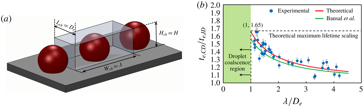
Confined droplet lifetime scaling analogy. (a) Schematic representing the confinement of CD (of an interacting three-droplet system) by a rectangular channel of dimensions:
 $L_{ch}\times W_{ch}\times H_{ch}$
. (b) Evaporation lifetime scaling of CD (of an interacting three-droplet system) with droplet separation values for two different forms of confinement (droplet–droplet and rectangular channel confinement).

10 Analogy with other confinement forms
Previous studies by Bansal et al. (Reference Bansal, Hatte, Basu and Chakraborty2017) and Hatte et al. (Reference Hatte, Dhar, Bansal, Chakraborty and Basu2019) have considered a different form of confinement wherein a single sessile droplet was symmetrically placed in a rectangular channel. In order to create an analogy between the present form of confinement (interacting three-droplet system) and the rectangular channel geometry, CD is assumed to be surrounded by a rectangular channel as depicted in figure 11(a). In order to establish an analogy, we cast the channel dimensions in terms of our three-droplet parameters as;
 $W_{ch}=\unicode[STIX]{x1D706}$
,
 $L_{ch}=D_{e}$
and
 $H_{ch}=H$
.
Equation (8.12) is rearranged in the following form:
 $$\begin{eqnarray}\frac{t_{e,CD}}{t_{e,ID}}=\frac{AK\unicode[STIX]{x1D6FD}\cos ec(\unicode[STIX]{x1D703}_{ci})A_{d,i}}{2R_{ci}\unicode[STIX]{x1D706}\sqrt{\unicode[STIX]{x03C0}(1+\cos ec\unicode[STIX]{x1D703}_{ci})}}+1.\end{eqnarray}$$
Using the values of channel dimensions from the analogy, the lifetime scaling formulation proposed by Bansal et al. (Reference Bansal, Hatte, Basu and Chakraborty2017) can be rearranged as follows:
 $$\begin{eqnarray}\frac{t_{e,CD}}{t_{e,ID}}=\frac{AKA_{d,i}}{0.7\times 2R_{ci}\unicode[STIX]{x1D706}}+1.\end{eqnarray}$$
In order to compare these two forms, the scaled evaporation lifetime of a CD (with respect to its ID counterpart) is plotted against variation of droplet separation values;
 $\unicode[STIX]{x1D706}=2L-D_{e}$
. A near perfect agreement (as seen from figure 11
b) with the present model and previous models for channel confinement (Bansal et al.
Reference Bansal, Hatte, Basu and Chakraborty2017) indicates the robustness of the scaling approach irrespective of the form of confinement. To establish the universality of the evaporation lifetime scaling, the present model must be extended for a two-dimensional array of sessile droplets. In addition, the scaling approach can be verified for working fluids with significant vapour pressure differential.
11 Conclusions
To summarise, the distinct evaporation dynamics of an ordered array of surface droplets, as compared to a single sessile droplet, is attributed to the vapour-mediated interactions resulting from the proximity of the individual droplets. The reduced mobility of diffusing vapour creates a region of vapour accumulation/confinement with enhanced vapour concentration. The resultant evaporation flux redistribution leads to strikingly altered internal flow dynamics of centre and side droplet(s). For the centre droplet, the accumulation/entrapment of vapour impedes its evaporation process, causing increase in its lifetime compared to its isolated droplet counterpart. Our generalisation in the underlying dynamics, as unveiled through a unique scaling of the lifetime of the centre droplet, agrees well with a wide range of experimental data. It can further be generalised that the case of an interacting three-droplet system mimics the evaporation dynamics of a general
 $n$
-droplet array
 $(n\geqslant 3)$
for any combinations of relative droplet positions. Striking analogies may also be drawn with the universal lifetime scaling of a sessile droplet enclosed in a physically confined space like a channel. Our results illustrate the possible applicability of the universal design of droplet configuration in a multitude of practical applications; for example, in genotyping and gene expression profiling that rely on the deposition of droplets of DNA solution on functionalised glass slides for on-spot analysis running over the droplet life span. An intricate control over the droplet lifetime by altering the precise regulations of the number density and positioning of droplets offers outstanding opportunities for tuning a simple generic structure of droplet arrays for specific applications such as biological assays for high throughput screening and medical diagnostics and deployment of low-cost and portable micro-lens arrays embedded for photonic manipulation on a film.