I. INTRODUCTION
The development and adoption of ultrasupercritical (USC) technology are a main and effective approach to decrease CO2 emission. Reference Viswanathan and Bakker1 But higher operation temperature and pressure need higher requirement for materials with good creep-resistant strength. Reference Niu, Gong, Jiang and Bao2,Reference Saucedo-Muñoz, Komazaki, Takahashi, Hashida and Shoji3 Creep and high-temperature resistant CrMoV steel has been successfully put into applications in power generation industry. Reference Hilkes and Gross4–Reference Hishida, Kobayashi and Nunokawa8 Especially for advanced 9–12%Cr materials recognized as the key materials to increase the thermal efficiency of steam power plants, they are increasingly used for large components such as turbines and boilers Reference Skleniĉka, Kuchařová, Svoboda, Kloc, Buršík and Kroupa9–Reference Tavassoli, Fournier, Sauzay, Fu, Kimura, Samaras, Serrano do Caro and Stroller11 to achieve good creep properties at temperatures above 600 °C. Reference Hättestrand, Schwind and Andrén12,Reference Hald13 9%Cr-1 (BM1) and 9%Cr-2 (BM2) are therefore developed by the research projects COST 501 and 522 for steam turbines of USC power plants to cater the demand of the higher creep resistance requirements. Reference Staubli, Kern, Mayer, Strang, Conroy, Banks, Blackler, Leggett, McColvin, Simpson and Smith14,Reference Kim and Kong15 BM1 steel can be characterized with an addition of Co and B, and no addition of W to further improve the creep strength and the target operating temperature is 650 °C. Reference Rothwell and Abson16,Reference Lu, Liu, Ji, Ding, Xu and Gao17 BM2 is modified by adding W to increase the creep strength and Cr content for better oxidation resistance. It has been widely used for high-pressure turbine applications for the USC plants built in Europe with steam temperatures up to 610 °C as a mature material. Reference Cui, Sun, Chen, Zhang, Wan, Shan and Wu18 Both of the two steels are the best candidates for the rotor steels. Reference Perrin and Fishburn19 They allowed the new generation of fossil-fired USC thermal power stations operating at live steam and reheat steam temperatures above 600 °C and supercritical live steam pressures up to approximately 300 bar or even higher. Reference Ulf, Marc and Brendon20
With increasing capacity combined with the requirement to reduce the delivery time and obtain various properties in the integrated structure, welding has been gradually used in the power industry to manufacture large components such as welded turbine rotors. Reference Shige, Magoshi, Ito, Ichimura and Kondo21 It was reported that the creep strength of welded joint is significantly lower than that in the case of base metal (BM) due to the complexity of welded joint. Reference Tanaka, Kubushiro and Takahashi22–Reference Laha, Latha and Rao25 The complexity of welded joint is the differing creep strength of the BM, weld metal (WM), and the disharmonious microstructures of the heat-affected zone (HAZ), when combined with the geometry and loading results in differing amounts of stress redistribution from weaker to stronger zones. Reference Skleniĉka, Kuchařová, Svoboda, Kloc, Buršík and Kroupa9,Reference Parker26 Rotor, whose failure is mainly caused by creep at operation temperature over 500 °C, is one kind of critical components in turbines. For the large-scale welded rotors with heavy section, the high-temperature performance of such components is often controlled by the creep behavior of the welded joints and most of the welded joint fractures in industrial components occur at HAZ because of inhomogeneous microstructures in this location. Reference Albert, Matsui and Hongo27,Reference Zhao, Jing and Xu28 So major efforts have been placed on the study of the creep deformation and failure of welded joints, especially the HAZ. Reference Hyde, Williams and Sun29 Spigarelli and Quadrini tested the P91 steel welded joint at 600 °C and found that the fine-grained heat affected zone (FG-HAZ) showed the maximum creep-rate values and the lowest creep strength. The coarse-grained heat affected zone (CG-HAZ) next to the WM generally had the greatest creep strength, whereas BM and WM exhibited an intermediate behavior. Reference Spigarelli and Quadrini30 Similar results were obtained by Kim and Lima during the creep experiments on P92 steel weldment and many creep cavities were observed at OT-HAZ. Reference Kim and Lima31 Tu et al. pointed out that the material mismatch in a weldment may produce significant influence on the damage development and creep crack growth rates of the weldment. Reference Tua, Seglec and Gong32 Zhao et al. investigated on the mechanism of “type IV” cracking in P92 steel at 650 °C and found that the number of creep voids increased at an accelerating rate and the maximum number of voids was formed in the FG-HAZ with varying creep times. The creep voids connected with each other and formed zigzag microcracks, leading to “type IV” cracking. Reference Zhao, Jing, Xu, An, Xiao, Xu, Chen and Han33 Falat et al. built “type IV” cracking failure mode in the FG-HAZ of E911/E911 and P92/P92 similar welded joints. The creep fracture location is usually associated with the smallest measured cross-weld hardness. Reference Falat, rostková and Homolová34
A large-scale rotor often includes several parts subjected to different temperature conditions, and it is necessary to join them together to take advantage of their potential performance and save cost. Reference Wu, Lu, Cui, Liu, Wang and Tang35,Reference Wu, Lu, Cui, Ding, liu and Gao36 So, it is very important to study the dissimilar welded joint for industrial applications. Also there were some reports that the BM1/BM1 and BM2/BM2 similar welded joints, those of grades 91 and 92, out-perform in long-term creep tests. Reference Castañeda and Pérez37,Reference Brozda and Maciosowski38 Unfortunately, little data on the long-term creep in BM1 and BM2 dissimilar welded joints are available until now due to the more complexities such as creep strength, fracture properties difference between them, and HAZs. Reference Samal, Seidenfuss and Roos39,Reference Collini, Giglio and Garziera40 Dissimilar metal welded joints are important parts of modern power and process plant equipment. Reference Laha, Chandravathi and Rao41 Narrow-gap (NG) welding is a low distortion welding process, allowing very thick plates to be joined. In the case of NG arc welding, because of lower heat input, it can remarkably reduce thermal stress leading to reduction in both residual stress and distortion. Reference Albert, Gill and Tyagi42,Reference Biswasa, Mandal and Vasu43 Here, NG submerged arc welding (NG-SAW) was used to weld BM1 and BM2 dissimilar steels, it is very important to investigate the reliability of dissimilar welded joint for the safe service.
In the present paper, a series of creep tests were carried out on the dissimilar welded joint at 538 °C under different stress loads to investigate the creep behavior. Based on the analysis of creep data, a 3-D curved surface describing the primary stage and steady-state creep stage would be fitted using MATLAB software, to determine the Norton–Power law constitutive equation parameters. The chemical composition of BM1 and BM2 makes the detailed microstructure change in HAZs in both sides of welded joint, which was revealed by optical microscope (OM) and scanning electron microscope (SEM). In this dissimilar welded joint, the soft zone in HAZ of BM2, special characters of δ-ferrite with extended size, and followed by amounts of carbides determine the creep property of a whole welded joint. Especially for microstructure evolution after a long-term creep test, the characters of cavity, δ-ferrite, carbides, and grain boundaries were discussed elaborately in this paper. The fracture location was determined by combining microstructures and hardness distribution in dissimilar welded joint.
II. EXPERIMENTAL PROCEDURE
A. BMs and filler metal
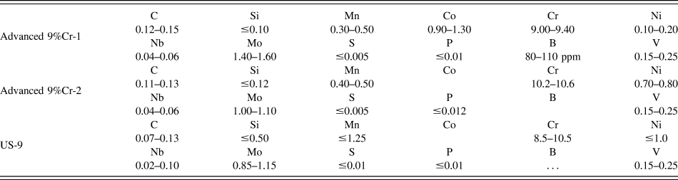
Advanced 9%Cr-1 and 9%Cr-2 materials were used to manufacture rotor steels with NG-SAW. US-9 was chosen as filler wire for its excellent creep rupture strength and match with 9%Cr steels. The chemical compositions of BMs and filler wire are listed in Table I.
Chemical composition of BMs and filler metal (wt%).

B. Welding procedure and heat treatments
The size of a trial rotor was about 900 mm in diameter made by a NG-SAW welding process, and multilayer and multipass techniques were used to join these dissimilar rotor metals. Post weld heat treatment (PWHT) was carried on dissimilar welded joint to obtain better comprehensive mechanical properties for the welded joint.
C. Creep fracture test
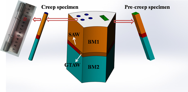
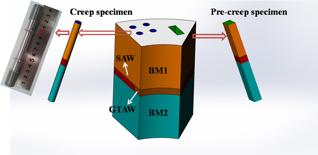
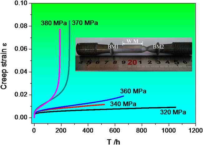
The rod-shaped uniaxial creep specimen with 10 mm in diameter and 50 mm gauge in length was adopted in the test. These specimens were taken from the dissimilar weldments, where WM was placed in the center of each specimen, as shown in Fig. 1.
Schematic of the specimens prepared for creep test.
Long-time creep tests were performed at 538 °C under different stresses with constant load tensile creep machines equipped with a split furnace in air. The temperature in the furnace was kept at the specified temperature with the precision of ±1 °C. The constant loads were applied on the specimens using dead weights with a high degree of accuracy for long durations.
The samples taken from the specimens after creep test for optical microscopy were prepared by cutting, grinding, polishing, and etching with a solution of HCl + HNO3 + H2O at the proportion of 3:5:5 so as to observe the microstructures with OM (Zeiss Image A2m). Scanning electron microscopy (SEM) was carried out to investigate the evolution of microstructures. Microhardness (Zwick/Roell) distributions were measured with a hardness tester with a constant load of 9.8 N for 10 s.
III. RESULTS AND DISCUSSION
A. Creep rupture test results
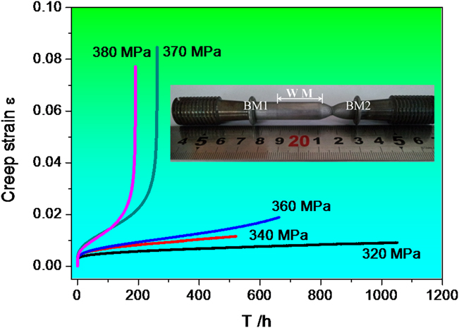
Experimental creep strain with time data was achieved at 538 °C under different stresses, shown in Fig. 2, where the tests of 320, 340, and 360 MPa were stopped without fracture. It is found that the creep strain rate increased with the increase of stress. Also, the rupture time of the creep test samples decreases as the stress increases.
Strain to time curves at different stresses at 538 °C.
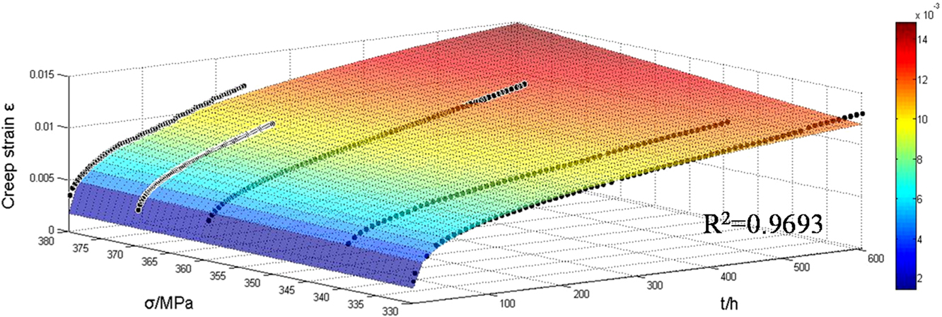
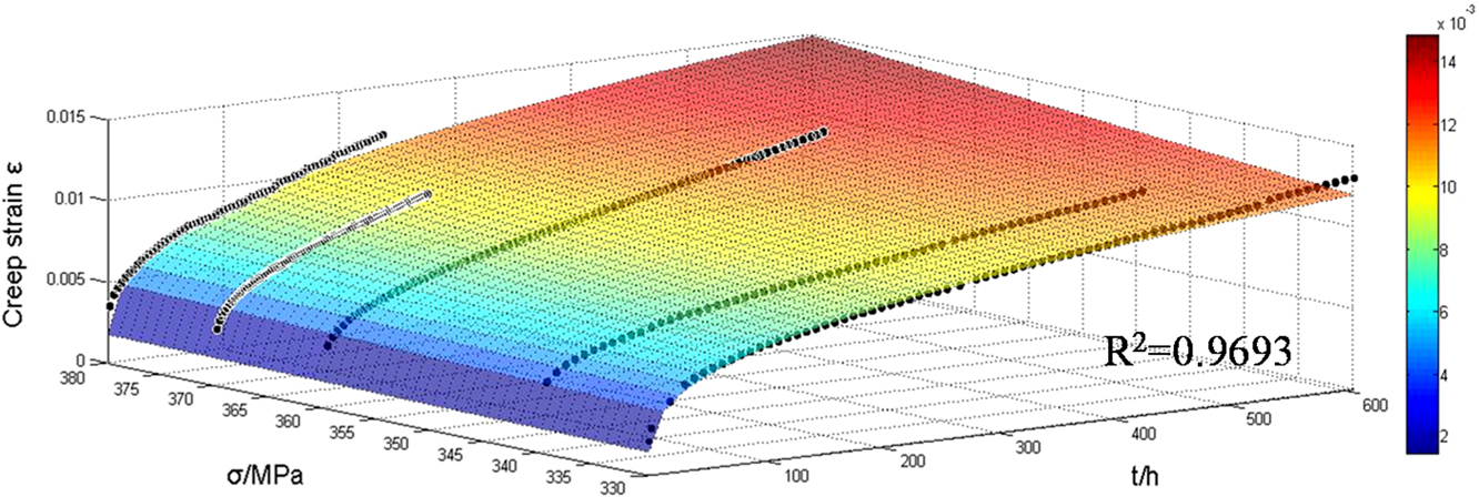
A 3-D curved surface fitted by MATLAB.
Norton–Power law is often used to estimate the creep behavior of the structures under different operating conditions, and the modified model is given in the following equation Reference Omprakash, Kumar and Srivathsa44–Reference Sawada, Tabuchi and Kimura47 :
 $$\varepsilon = A{\sigma ^n}{t^m}\quad {\rm{,}}$$
where, ε is the state creep strain, σ is the stress, and t is the time. A, n, and m are temperature dependent material constants that are generally independent of stress. While n and m represents the creep strain hardening coefficients without unit, but A has a unit of MPa−n h−m .
A computer program based on “MATLAB” was developed to predict creep curves, both primary and steady-state creep stage have been addressed. The creep curves were generated at different stress levels of 538 °C. The 3-D predicted creep curve surface (shown in Fig. 3) indicated quite match with experimental creep curves. The parameters were calculated and are shown in Table II, which agrees well with the predicated parameters of simulated Fe–Alloy Reference May, Gordon and Segletes48 and better than STPA23 steel. Reference Takazawa and Yanagida49
Creep constants of dissimilar weld joint.

B. Microstructures of the precreep welded joint
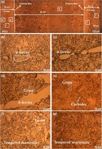
The microstructures of the BM1 and BM2 steel precreep welded joints are shown in Fig. 4. The microstructure of WM is mainly tempered martensite, which is favorable to produce good mechanical properties. A considerable amount of δ-ferrite was revealed in the HAZ of BM2 due to overheating during welding process. It is reported that the presence of δ-ferrite can cause a remarkable loss of creep strength ductility and toughness in the long-time creep condition. Reference Kobayashi, Sawada and Hara50–Reference Lia, Eliniyaza and Zhanga52 It can also be found that δ-ferrite presented a disk shape and a bumpy interface, and also some carbides homogeneously precipitated in δ-ferrite especially in the OT-HAZ. On the contrary, no δ-ferrite was found on the side of BM1 attributing to the high Co content. It is deemed that Co element can reduce δ-ferrite formation and can improve creep strength and toughness. Reference Onoro51,Reference Hong, Rho and Nam53 The microstructures difference of the two BMs could be used as an evidence to judge the fracture location after creep test.
Optical microstructures of the precreep welded joint: (a) whole welded joint, (b, c, d) BM2-HAZ, (e, f) BM1-HAZ, and (g) WM.

C. Microstructures of the aftercreep welded joint
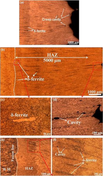
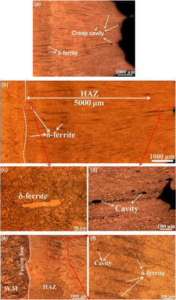
Figure 5 shows the microstructures of the welded joint after creep rupture. As shown in Figs. 5(a) and 5(b), based on the existence of δ-ferrite and the width of HAZ, it is determined that the fracture location is located in the HAZ adjacent to BM2. It can be observed that many voids occur near the fracture, and some of them coalesce and then form cracks. Closer to fracture location, more voids appeared. There are also many black streaks elongated by creep stress, where the creep cavities are formed easily, shown in Fig. 5(d). It is deemed that δ-ferrite rows were surrounded by the black streaks spreading through the HAZ region to the fracture location.
Optical microstructures of the fracture creep specimen at 538 °C with the stress of 370 and 380 MPa: (a, b) fracture location with the stress of 370 MPa, (c) microstructure of HAZ around the fusion line, δ-ferrite could be clearly observed, (d) microstructure of fracture location, creep cavity could be clearly observed, (e) optical microstructure of the fracture creep specimen at 538 °C with the stress of 380 MPa, and (f) microstructure of HAZ around the fusion line, many elongated black streaks and some of the cavities could be clearly observed.

D. Analysis on the fracture location
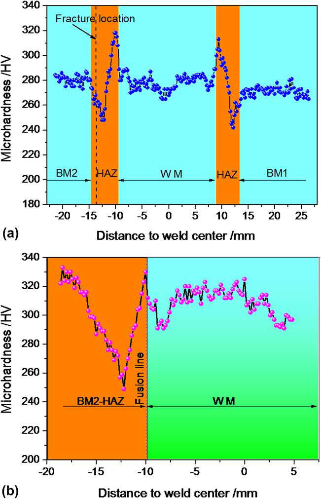
Vickers microhardness distributions over the cross-sections of the precreep specimen and the fracture creep specimen are presented in Fig. 6.
Microhardness distribution across welded joint: (a) precreep and (b) aftercreep at 538 °C with the stress of 370 MPa.
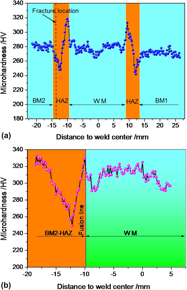
It can be observed that the hardness near the fusion boundary in the HAZ is the highest, both before and after creep, and the region adjacent to the BM is lower due to the overheating during the welding process. The lowest hardness area is located at 4000 μm away from the fusion boundary in both sides, corresponding to the OT-HAZ. There are two soft zones in both sides of the HAZs, where the hardness is lower compared with other locations based on hardness tests. The competition of quite different HAZs of both sides for dissimilar welded joint determines the final properties of welded joint, where microstructure in grain zone, fine grain zone, and overtempered zones brings more difficulties in analysis. The hardness of the WM, HAZ, and BM tends to increase due to creep deformation. In addition, the hardness in the OT-HAZ of the rupture specimen increases greatly than that in other zones of the welded joint. The highest hardness is located in the rupture edge as a result of the redistribution of elements (carbon, chromium, etc.) and the maximum plastic deformation generated in this zone as shown in Fig. 6(b).
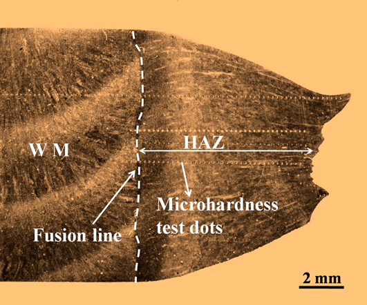
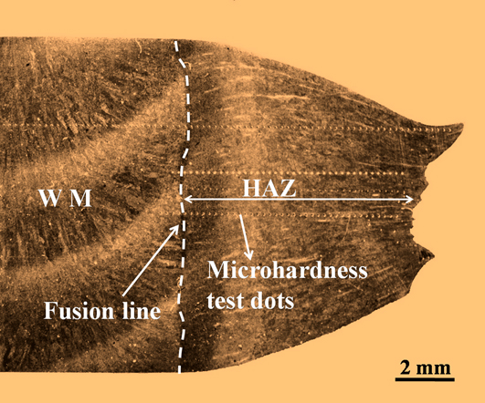
To determine the fracture location, it is supposed that the volume of the precreep specimen is approximately equal to the aftercreep one. From Fig. 7, it can be calculated that the volume of a deformation part should be equal to the volume of the cylinder. So the distance from fracture to fusion line is calculated around 4.35 mm. The fracture location is marked by the black dotted line in Fig. 6(a).
Longitudinal section of the fracture specimen.
E. Microstructure evolution
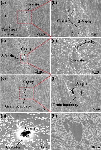
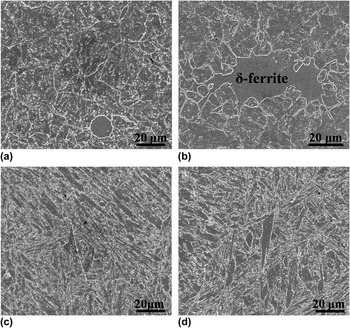
To examine the nucleation sites and propagation process of creep voids, SEM observation was carried out on the fracture and the precreep specimen. Figure 8 shows the SEM micrographs of various microzones in the fracture creep specimen at 538 °C with the stress of 370 MPa. Compared with the SEM micrographs of the precreep welded joint (Fig. 9), it can be observed that cavity nucleation occurs mainly at grain boundaries, more precisely, at triple points and interfaces between the matrix and δ-ferrite or second phase particles. The tempered martensite boundaries in the HAZ gradually become obscure after creep, shown in Fig. 8(h). Due to the lowest peak temperature and the shortest dwell time at peak temperature during welding in this area (OT-HAZ), a large amount of undissolved carbides which are apt to become coarse and stimulate the nucleation of creep voids generated in the grain boundaries, as shown in Figs. 8(e) and 8(f). The carbides size and density obviously increase after creep, as shown in Fig. 8(g). Particularly, the largest size and density of cavities are adjacent to the δ-ferrite boundaries as shown in Figs. 8(a)–8(d).
Microstructures at different zones after creep: (a, b, c, d) cavities at δ-ferrite. Boundaries close to the location of fracture (OT-HAZ), (e, f) cavities at grain boundary, (g) nucleation sites of creep voids, and (h) affected base material.

The micrographs of precreep specimen: (a, b) microstructures of the HAZ, (c) BM1, and (d) BM2.

IV. CONCLUSIONS
Based on the creep test of dissimilar welded joint, microstructure degradation and creep void formation were elaborately analyzed and investigated in the study. The conclusions can be summarized as follows:
-
(1) The 3-D predicted creep curve surface was fitted based on the creep data, the constitutive equation was determined as ε = 1.88 × 10⁷σ1.58 t 0.30. This equation can provide the reference for this dissimilar welded joint in estimating the creep lifetime.
-
(2) Many δ-ferrite microstructures are observed in the HAZ of BM2 side with a disk shape and a bumpy interface. And they were elongated during the creep test like the black streaks spread through the whole HAZ region to the fracture location, where the creep voids tended to occur around them.
-
(3) Fracture is located at OT-HAZ, which is the most dangerous part in the welded joint in creep conditions. Numerous creep voids were located around the δ-ferrite and finally formed microcrack by SEM observation. Many carbides and second phases in the grain boundary are the preferential sites for cavity nucleation; and also the tempered martensite boundaries in the HAZ gradually became obscure as the creep time increases.
ACKNOWLEDGMENTS
The authors gratefully acknowledge the financial support by Shanghai Science and Technology Committee (No. 13DZ1101504).