I. INTRODUCTION
Light polarization technique is a new branch of modern optical technology, which is widely applied in detecting and optoelectronic field including fiber-optic communication, optical disk memory, optical modulation, and optical sensor. With the rapid development of photoelectric integration technology, the preparation of polarizing component with large size and thin film structure become the focal point of research now. Many preparation methods have been developed to fabricate the micropolarizer by technique of physical sputtering, molecular beam epitaxy, electron beam etching, and so on.Reference Baba, Shiraishi, Obi, Kataoka and Kawakami1–Reference Guo and Brady3 However, the traditional preparation techniques above are rather complicated with adoption of expensive equipment, whereas the size of polarizer is small, which cannot meet the needs of application in integrated optoelectronics field. In 1989, metal nanowire arrays formed in alumina film have been reported to yield a polarizing effect in near infrared (IR) wavelength theoretically and experimentally.Reference Saito, Kirihara and Taniguchi4 Thus a new way was pioneered for the preparation of micropolarizer with adoption of nanotechnology, though the film is too fragile to obtain actual application.
In fact, the noble metal nanoparticles have received enormous attention due to their unique optical, electronic, chemical, and thermal properties.Reference Sau, Rogach, Jackel, Klar and Feldmann5–Reference Burda, Chen, Narayanan and El-Sayed7 Especially the surface plasmon resonances excited by an incident photon beam have a vast number of potential applications such as optical computers, optical switches,Reference Sandrock, Pibel, Geiger and Foss8, Reference Nikolajsen, Leosson and Bozhevolyni9 and biosensors.Reference Raschke, Kowarik, Franzl, Sonnichsen, Klar, Feldmann, Nichtl and Kulrzinger10 Furthermore, the optical properties of the noble metal nanoparticles can be tuned by the fine control of several particles’ parameters, including size, shape, aggregation state, and the nature of the surroundings.Reference Kelly, Coronado, Zhao and Schatz11
To utilize the special properties of noble metal nanoparticles, it is essential to realize the preparation of special shape nanoparticles and to assemble the nanoparticles with bulk phase in various forms. Till now, people have done much on controllable preparation of noble metal nanoparticles with special structure and special morphology,Reference Sun and Xia12–Reference Skinner, Dwyer and Washburn15 and major efforts have been devoted on the development of assembly methods.Reference Zhao, Roberge, Yelon and Veres16–Reference Yu, Cao and Lieber20 However, there are only a few reports about the assembly of noble metal nanoparticles, as basic units, to form nanoscale-aligned structure in bulk materials, which is often termed as nanocomposites.
The pioneering work about the preparation of nanocomposites containing metal nanoparticles was done in 1960s by Skillman et al.,Reference Skillman and Berry21 who demonstrated the alignment of spherical silver colloid particles in a drawn glass belt. After that, a few technical waysReference Grossman, Vandegrift, Williams and Whitbred22–Reference Borrelli, Mann and Whitbred24 have been reported on how to improve it. However, most of them are based on a direct, in-situ formation of the metal nanoparticles within the glass matrix, which needed to adopt the technique of high-temperature melting, powerful stretching, and high-pressure reduction. Our research group has studied the preparation and the novel properties of the Ag-doped glasses by the above method systematically.Reference Wang, Han, Gong, Chen, Zhao, Feng and Ren25, Reference Feng, Zhao, Liu and Zhou26 Meanwhile, we put forward a method by using a wire grating-assisted ultraviolet to obtain a large size Ag-doped glasses without stretching process.Reference Lin, Tao, Feng, Gong, Pan and Zhao27 And because of the technical limitation, the control of particle size, composition, and morphology is very difficult. A major breakthrough of the approaches has been reported by Matsuda et al.,Reference Matsuda, Yasuda and Ando28 who prepared the uniaxially drawn polymer-blend films doped with AgNO3, by reduction at high temperatures, in which uniformly aligned silver nanorods were precipitated. Matsuda et al. used polymer as the matrix instead of glass. It is well known that there are many similar properties between polymer and glass (or glass melt), such as transparence, amorphous, viscous behavior, and so on. Besides that, polymer has many advantages, including low work temperature, high plasticity, easy operation, and multiple molding methods. So polymers may be a more suitable matrix for the fabrication of composites with nanoscale aligned structure of metal particles.
Another approach for the preparation of nanocomposites was reported by Dirix et al.,Reference Dirix, Bastiaansen, Caseri and Smith29 who synthesized metal nanoparticles with special shape by chemical methods, then introduced the metal nanoparticles into the matrix to fabricate composites with nanoscale aligned structure. They dispersed spherical silver nanoparticles in polyvinyl alcohol (PVA), and then prepared thin films by drawing at 120 °C to realize the alignment of Ag nanoparticles in the film. Further improved methods were published by several recent papers.Reference van der Zande, Page`s, Hikmet and van Blaaderen30–Reference Juste, González, Mulvaney and Liz-Marzán32 Thin films of gold (or silver) nanorods dispersed in PVA were prepared by drawing at the softening temperature of the polymer. Using this method, the morphology of the nanoparticles should be tailored more easily during the processing of presynthesization, compared with the in-situ formation of the metal nanoparticles within the matrix, thus more types of nanoscale aligned structure can be realized. But so far, only PVA is used as the matrix to disperse metal nanoparticles in all the reports. The dispersion of metal nanoparticles in PVA or the stretching of PVA to form thin film must be operated at the soften temperature because PVA is a thermoplastic polymer. At the same time, the drawing ratio of PVA is rather small which results in the PVA film with big thickness and a small relative slipping of proximate flow layers. The thick PVA film will absorb a substantial portion of the incident light and, consequently, the transmittance of the film is small. Because of lack of enough shear stress and tensile stress, a tangled structure tends to be formed in the film, especially for metal nanowires, which will result in a poor alignment of metal nanoparticles in the films.
In this study, we demonstrate a new method to prepare well-aligned Ag nanoparticles dispersed in epoxy resin as the matrix by the transfer of presynthesized metal nanoparticles into the matrix. Firstly, Ag nanowires with diameters of 60–85 nm and length of 10–20 μm were synthesized by seed-mediated chemical method. Then the homogeneous dispersion of silver nanowires in epoxy precursor was realized. Lastly, the epoxy doped with Ag nanowires was stretched at room temperature to form thin film with final thickness of 15–16 μm. Also, the Ag/epoxy nanocomposite materials showed obvious IR polarization properties in a broad wavelength range from 1600 to 2600 nm and a transmissivity of over 70%.
II. EXPERIMENTS
A. Reagent, instrument, and testing conditions
Silver nitrate (AgNO3, 99.8%), ethylene glycol (EG, 99.8%), hydrogen tetrachloro-aurate (III) trihydrate (HAuCl4·3H2O, 99.9%), and anhydrous ethanol (EtOH, 98%) were purchased from Shanghai Chemical Co., Ltd., Shanghai, Peoples Republic of China. All chemicals were used as received without any purification.
Polyvinylpyrrolidone (PVP, K30, Mw∼44,000–54,000) was obtained from Shanghai Bio Life Science & Technology Co., Ltd., Shanghai, Peoples Republic of China. Epoxy resin (product grades: 601, CYD-115, epoxy equivalent < 0.25) and modified amine solidifying agent (product grades: T31) were obtained from China Petrochemical Group Baling Petrochemical Sub-Co., Ltd., Yueyang, Peoples Republic of China.
The morphology and size of silver nanowires as well as the microstructure and energy spectrum analysis of the surface of Ag/epoxy film coated on the glass substrate were characterized by scanning electron microscope (SEM, JSM—5610LV; JEOL Ltd., Tokyo, Japan) and transmission electron microscope(TEM, JEM 2010, JEOL Ltd., Tokyo, Japan). Lattice fringes of single silver nanowire had been observed by high-resolution transmission electron microscopy (HRTEM, JEM 2100F; JEOL Ltd., Tokyo, Japan).
The microstructure of the samples was characterized by field emission SEM (SIRION SEM, FEI Co., Eindhoven, Netherlands).
Characterization of the microstructure and energy spectrum analysis have been studied by SEM.
Polarization transmittance performance of the glass samples was test by UV-Vis Spectrophotometer (UV-1601; SHIMADZU Co., Kyoto, Japan) in the wavelength range from 200 to 1100 nm.
The microstructure of directional alignment of silver nanowires had been studied by super depth digital microscope (SDDM, KEYENCE Co., Osaka, Japan, VHX-600K; JEOL Ltd., Tokyo, Japan).
Research on the transmittance of polarized light of Ag/epoxy film coated on the glass was carried on by FTIR-Spectrometer (VERTEX 70/70v; BRUKER OPTICS Ettlingen, Germany) in the range of wavelength from 1350 to 3000 nm.
B. Synthesis of Ag nanowires by seed-mediated method
Silver nanowires were synthesized by reducing AgNO3 in EG which was used as reducing agent and solvent.Reference Chen and Gao33 PVP was introduced as structural directing agent and gold nanoparticles were used as seeds. The optimum experimental procedure was as follows: Twenty milliliters of EG was put into a beaker, which was firstly heated up to 175 °C in an oil bath under vigorous magnetic stirring. Then 20 droplets (∼1 mL) of 0.005M HAuCl4 aqueous solution were added into the above heated EG solution. When the color of the solution turned from yellow to pink, it indicated the gold nanoparticles were formed. Five minutes later, 0.2 g of AgNO3 (dissolved in 10 mL of EG) was added into the beaker. Just after the addition of AgNO3, 0.33979 g of PVP (dissolved in 20 mL of EG) was added dropwise over a period of 15 min. The molar ratio of PVP repeating units to Ag was 2.6. The reaction went on for another 60 min. During the whole reaction process, the temperature was kept at 170–175 °C and the vigorous magnetic stirring continued. The mixture of reaction gradually turned turbid and a yellow–gray suspension was obtained. The suspension was washed with ethanol and then centrifuged repeatedly under the rotation speed 3000 rpm/min. The collected precipitates were dried for 2 h in a vacuum drying oven at less than 60 °C.
C. Dispersion of silver nanowires in the epoxy precursor
The above-prepared silver nanowires (20–500 mg) were added into the 12.5 g ethanol to obtain Ag nanowires ethanol suspension solutions, and the suspension was poured into a 50 g epoxy precursor solution under vigorous mechanical stirring. Then 12 g epoxy solidifying agent was added into the epoxy precursor solution, stirring went on for another 60 min. Finally, the epoxy precursor solution was capped and let stand for 24 h until the viscosity of the epoxy precursor solution reached 600–650 Pa·s (measured by DV-II+Prog viscometer, Brookfield, Guangzhou Pulifei Scientific Instrument Co. Ltd., Guangzhou, Peoples Republic of China).
D. Preparation of Ag/epoxy nanocomposite film
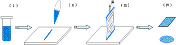
Preparation of Ag/epoxy nanocomposite film includes two steps of stretching and coating. As shown in Fig. 1, the stretching process was carried out by sucking 2–2.5 g of epoxy solution into a plastic tube (about 1cm in outer diameter) and then extruded out on a platform plate to form an epoxy resin strip, then the epoxy resin strip held by a clamp was drawn up smoothly at the speed of 30–150 mm/min controlled by a stepping motor. The Ag/epoxy nanocomposite film was formed during this stretching process. After that the Ag/epoxy nanocomposite film was transferred to the glass substrates pretreated by pure water, acetone, and 0.1% KH-560 alcohol solutions.
Illustration of preparation process of Ag/epoxy nanocomposite film. (I) suspension of a Ag nanowires epoxy resin, (II) extruding of epoxy resin strip on a platform, (III) stretching of epoxy resin film by a stable stretching force F, which is applied by a clamp, (IV) transfer of Ag/epoxy film onto a glass sheet or other substrates. (Note: The black short lines in the figure represent Ag nanowires.)

It should be noted that when the Ag/epoxy nanocomposite film was transferred onto glass substrates after the stretching, the glass sheet should be tilted in a certain angle to move toward the film, so that the epoxy film could join with one end of the glass sheet, then join with other parts of the glass gradually by adjusting the tilting angle to avoid the formation of pores between the film and the glass substrate.
E. Testing method of polarizing property of samples
The polarizing property of the series of samples was studied by FTIR-Spectrometer. The testing steps were as follows:
(i) We put the samples on the FTIR-Spectrometer, adjusting the polarizing angle of polarizer in the spectrometer in optical field to make the electric vector of polarized light perpendicular to the stretching direction of the film, and then testing the transmittance of the sample.
(ii) We rotated the polarizing angle of polarizer with an angle of 90°, making the electric vector of polarized light parallel to the stretching direction of the film, and then testing the transmittance again.
III. RESULTS AND DISCUSSION
A. Characterization of Ag nanowires synthesized by seed-mediated method
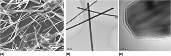
Figure 2(a), the SEM images of the synthesized Ag nanowires, shows that the uniform straight nanowires with high yield had been successfully achieved by the seed-mediated method. The lengths of Ag nanowires are in the range of 10–20 μm. Figure 2(b), the TEM image of four long and straight Ag nanowires, shows that the diameters of Ag nanowires are in the range of 60–85 nm. Figure 2(c) shows the HRTEM image of a single silver nanowire, showing the lattice fringes separated by 2.33Å which is very closely to the standard {111} crystal spaces (JCPDS file No.04-0783) of face-centered cubic silver metal. This result is in agreement with previous studies.Reference Sun, Mayers, Herricks and Xia34
(a) Scanning electron microscopy (SEM) image of the as-synthesized silver nanowires by seed-mediated method, which show that almost all of the synthetic products are nanowires. (Note: The scale bar is 1μm.) (b) Low-magnification TEM image of the as-synthesized silver nanowires by seed-mediated method. (c) High-resolution transmission electron microscopic image of single Ag nanowire.

The formation of anisotropic silver nanostructures involves the following steps: Firstly, the seeds of gold nanoparticles were in situ achieved by reducing HAuCl4 with ethylene glycol, with diameters in the range of 3–5 nm. Secondly, when AgNO3 and PVP were added dropwise to the reaction system, silver atoms could be achieved by reducing reaction and silver particles would nucleate and grow up.Reference Huang, Ni, Loy, Chew, Tan, Loh, Deng and Xu35–Reference Silvert, Urbina and Elhsissen37 With the assistance of PVP, some of the large nanoparticles were able to grow into rod-shaped structures. The mechanism for the formation of the one-dimensional (1D) nanostructures has been proposed by Xia and colleagues.Reference Sun, Mayers, Herricks and Xia34 They thought that the different reactivity of PVP with {100} or {111} facets of silver nanoparticles makes decisive effects on the formation of the 1D silver nanostructures. The interaction between PVP and {100} facets is much stronger than that between PVP and {111} facets, and the silver atoms always prefer to diffuse to the ends of nanorods or nanowires owing to their higher chemical potential and reactivity.Reference Sun and Xia38, Reference Sun, Yin, Mayers, Herricks and Xia39
Figure 2(a) shows that some other small particles were produced simultaneously. They will be removed by the following centrifugal separation. These small particles should be silver particles because the diameter of gold seed is too small to be visible. These particles have a structure of Au core and Ag shell according to reference.Reference Tsuji, Matsumoto, Miyamae, Tsuji and Zhang40 And Ag shell could be overgrown on the Au core decahedral facets due to the same crystal structure and similar lattice constants of Au as Ag.
Furthermore, we can see from Fig. 2(c) that there is a thin cover layer on the surface of Ag nanowire, resulted from the absorption of PVP on the surface of metal particles.Reference Sun, Mayers, Herricks and Xia34 The formation of the cover layer will benefit to the homogeneous dispersion of silver nanowires in epoxy precursor solution.
B. Characterization of Ag/epoxy nanocomposite film coated on glass
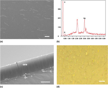
Figure 3 shows the SEM image, Energy dispersive x-ray analysis (EDAX) spectra, and cross-section and the optical microscope image of the Ag/epoxy nanocomposite film coated on a glass prepared under the following conditions: The weight ratio of Ag nanowires to epoxy is 0.24wt%.The ratio of solidifying agent to epoxy is 0.24. The polymerization time is 24 h. The stretching speed is 75 mm/min.
(a) SEM image of the surface of Ag/epoxy film, showing the alignment of nanowires in the film. (b) SEM-EDAX spectrum of nanowires in the image of (a), verifying that the chemical composition of nanowires is silver. (c) SEM image of the cross-section of Ag/epoxy film coated on glass, showing the film thickness of 15.1um. (d) Optical microscope image of the surface of Ag/epoxy film, showing an even richer structural characteristic of the alignment of individual Ag nanowires. [Note: The scale bar of (a) and (c) are 10μm. The scale bar of (d) is 20μm.]

Ag nanowires are well dispersed and aligned in the epoxy resin without obvious agglomeration [see Figs. 3(a) and 3(d)]. Almost all the Ag nanowires are extended into straight lines and oriented in the direction of film stretching. Comparing Figs. 3(a) and 3(d), we can see that the SDDM has an even richer structural characteristic of the alignment of individual Ag nanowires than SEM. Figure 3(b) shows that the nanowires in the film are consisted of elements Ag, O, and C. Elements O and C are the basic elements of the epoxy film. So it can be further confirmed that the nanowires in the stretched film are Ag nanowires. Figure 3(c) shows that the thickness of the Ag/epoxy nanocomposite film coated on glass is about 15.1 μm.
C. Microstructure of the Ag/epoxy nanocomposite film and the orientation mechanism of Ag nanowires
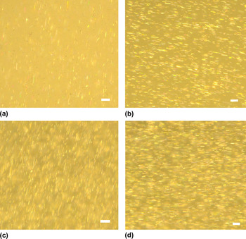
Figure 4 shows optical micrographs of the Ag/epoxy nanocomposite films coated on glass prepared by a stretching speed of 140 mm/min, and other preparation parameters are as follows: The weight ratio of Ag nanowires to epoxy is 0.08–0.66wt%, and the ratio of solidifying agent to epoxy resin is 0.24. The polymerization time is 24 h.
Optical microscope images of the surfaces of Ag/epoxy films with different Ag nanowire concentrations with weight ratio of Ag nanowires to epoxy is (a) 0.08, (b) 0.32, (c) 0.48, and (d) 0.66%. [Note: The scale bars of (a)-(d) are 10 μm.]

From Fig. 4, it is found that the amount of Ag nanowires in unit surface of film increases and the interval distance among Ag nanowires decreases gradually with increasing concentration of Ag nanowires in the film, and Ag nanowires are kept dispersed well and oriented in same direction. Compared with Fig. 3(d), we can see that Ag nanowires show better alignment when stretched by higher speed.
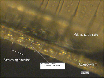
Figure 5 shows the optical-microscope photograph of the cross-section of Ag/epoxy nanocomposite film coated on glass. Ag nanowires are aligned well along with the drawing direction not only in the surface but also in the internal of the film.
Optical microscope image of the cross-section of Ag/epoxy film coated on glass, with the same sample as Fig.4(b), showing that the typical thickness of the film is 16.41 μm and Ag nanowires are aligned well along the stretching direction (white arrow) inside the film.

Two reasons can be considered to cause the alignment of Ag nanowires. The first reason is that a continuous tensile stress acts on the epoxy resin strip during the stretching process, which let the strip be drawn into a thinner and thinner film. During this process, a shear stress and tensile stress caused by relative slippage of adjacent flow layer of the epoxy resin will apply on Ag nanowires, which is an important reason for the alignment of Ag nanowires along the stretching direction.
The second reason is in view of microscopic aspect. It is well known that the polymer molecules always have dissymmetrical morphology, and there is large difference in surface property existed between the lateral and longitudinal dimensions of a macromolecule. In a free state, the macromolecules tend to curl and to entangle with each other to form a mess molecular clew. However, when a shear stress or tensile stress is applied on the polymer, the macromolecular chains or chain segments of the polymer will be oriented along the stretching direction to form aligned structure, which will also act on the Ag nanowires. Figure 6 confirms the occurrence of this process, which shows the polarizing transmittances of a stretched blank epoxy film sample without Ag nanowires. With the increase in the angle between the electric vector of the polarized light and the drawing direction of epoxy film from 0° to 90°, the transmittance increases gradually. Although the amplitude variation of transmittance is small with a typical value of 0.02, it confirms that the generation of optical anisotropy of the stretched film, which is resulted in the formation of aligned microstructure during stretching process. It is similar to the previous studies reported.Reference Buffeteau, Desbat and Bokobza41
Transmittance spectra of a stretched blank epoxy film without Ag nanowires for the different angles between the electric vector of the polarized light and the drawing direction of epoxy film.

However, the aligned microstructure existed in a polymer is a nonequilibrium state which will recover to a mess molecular clew structure once the acting force is removed. To maintain the aligned microstructure, the stretched film should be immediately coated on the surface of glass sheet, so the stress force from the glass substrate will act on the film to maintain the aligned microstructure. Hence, the alignment of the chain segments of polymer will benefit to Ag nanowires aligned in a better order.
D. Optical polarizing of Ag/epoxy nanocomposite film coated on glass
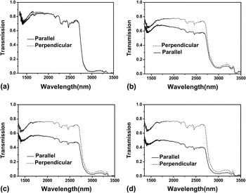
Figure 7 shows the polarizing transmittance spectra of samples prepared by a stretching speed of 140 mm/min with different weight ratio of Ag nanowires to epoxy. Figure 7(a) is the polarizing transmittance spectra of the blank epoxy resin film without Ag nanowires, which shows that the transmittance curves are almost same under parallel and perpendicular condition. As the concentration of Ag nanowires increases Figs. 7(b)–7(d) show that the polarizing light transmittance has changed largely when the polarizing direction of the incident light changed from parallel to perpendicular and the transmittance is lower under a parallel condition than under a perpendicular condition in the wavelength range from 1350 to 2600 nm. The results indicate a rather obvious IR polarization property of the Ag/epoxy samples in a broad wavelength range from 1350 to 2600 nm. The curve is nearly smooth in a wide wavelength range from 1600 to 2600 nm, and only small peaks at the wavelength of 2160, 2320, and 2460 nm are found due to the absorptions of unidentified OH combination band, combination bending, and stretching of OH in silanol groups of the glass substrates,Reference Davis and Tomozawa42 respectively. Meanwhile, the transmittances of the samples are over 70%.
Polarizing transmittance spectra of the samples with different weight ratio of Ag nanowires to epoxy (a) 0, (b) 0.08, (c) 0.32, and (d) 0.66%. Note: Solid curve and dotted curve represents incident field polarized parallel or perpendicular to Ag nanowires orientation direction, respectively.

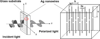
The polarizing effect of the samples is a result of the interaction of oriented Ag nanowires in the Ag/epoxy film with optical wave. Here, the silver nanowires with a length of 10–20 μm are arrayed well in the epoxy film, which is very similar to the structure of a micrometallic wire grid polarizer (see Fig. 8). Thus we should adopt the polarizing theory of metal nanoarrays micropolarizer to analyze the polarizing property of the film. However, till so far there are few studies about the mechanism and theory of polarizing property of metal nanoarrays structures. In 1989, Saito presented a theory based on Gans’s method developed for wire grids to evaluate the optical loss of metal nanoarrays micropolarizer.Reference Saito and Miyagi43 From Figs. 7(b)–7(d), we have obtained polarizing property of Ag/epoxy film samples as follows, which is similar to the calculated result of Saito. First, the optical transmission of film depends strongly on the polarization direction of the incident light and increases significantly when the polarization direction is changed from parallel to perpendicular to the nanowires. Second, metal nanoarray systems have shown polarizing property over a wide IR wavelength range. Third, the amplitude difference of transmittance between parallel and perpendicular conditions is increasing with increasing wavelength, which is most obvious in Fig. 7(b).
Illustration of the polarization property of the Ag/epoxy samples. The right image shows the enlarged structural model of aligned Ag nanoarrays in Ag/epoxy film. Ag nanowires with radius (a) and length (c) are arrayed at an average interval (b).

In the prepared Ag/epoxy film samples, the radius of Ag nanowires is much smaller than the wavelength of incident light, according to Saito’s theory, so the total loss of the film α total = α A + α S can be simplified and evaluated as follows:


where α A denotes an absorption loss and α S denotes a scattering loss, structural parameters are Ag nanowires radius a and an average interval b between adjacent Ag nanowires. Equations (1) and (2) indicate that the absorption loss is in proportion to the volume fraction of the Ag nanowires, whereas the scattering loss is in proportion to the square of the volume of a single Ag nanowire and it increases as Ag nanowire radius a increases.
Considering the results in Fig. 7 with Fig. 4, we can see that the difference in transmittance between parallel and perpendicular conditions increases gradually with increasing concentration of Ag nanowires in the film. Here, the radius a of Ag nanowires is nearly uniform by centrifuged, the increase in concentration of Ag nanowires in Ag/epoxy film only leads to the decrease in the average interval distance b, which results in a higher value of a/b. According to the equations, both the absorption loss and scattering loss increase with increasing value of a/b, while the absorption loss increases more obviously. For a metal nanoarray structure, when the electric vector of polarized light is parallel to the axis of Ag nanowires, free electrons will move along the axis of nanowire droved by the electrical field of incident light. The collision of the electrons with crystal lattice will lead to energy loss, which corresponds to the absorption loss. But when the electric vector of polarized light is perpendicular to the axis of Ag nanowires, the movement of electrons driven by electrical field of incident light will be perpendicular to the axis of nanowire, and the movement is limited by the nano size of Ag nanowires. So the absorption loss can be ignored under perpendicular condition. The total loss of light under parallel condition is higher than that under perpendicular condition, and with the increase in value a/b, the difference between the losses obtained under different conditions will be even larger, which leads to an even larger difference of transmittance obtained under different conditions. This is in agreement with the theory prediction.
Of course, only the spectrum in the range of 1600–2600 nm was shown here, and the polarizable behavior of this range may be applied in the field of IR detection. Indeed, the preparation method is an excellent way with high adjustability. The wavelength range is determined by the length of silver nanowires and their intervals,Reference Saito and Miyagi44 and if we change the fabrication condition, we may get a different range with polarizable behavior for different applications. For example, Ag/epoxy film with polarizing effect in visible wavelength range may be applied in displayer. The film with polarizing effect in the wavelength range of 1000–1600 nm may be applied in fiber-optic communication. The major advantage of the preparation method is that the large area film with widely polarizing wavelength range can be fabricated with convenience and high adjustability, and the shift of the range will be our future study.
IV. CONCLUSIONS
With several steps of process including presynthesization of Ag nanowires by seed-mediated method, homogeneous dispersion of Ag nanowires in the epoxy resin, and the preparation of Ag/epoxy film by stretching method Ag nanowires were aligned well along the same direction in the whole body of epoxy resin film. We demonstrate features of Ag/epoxy nanocomposite film doped with Ag nanowire of different concentrations or obtained by different stretching speed. The studies of polarization property of Ag/epoxy nanocomposite film demonstrate that its performance is similar to that of metal nanoarray wire grids micropolarizer. We believe that the spreading and aligning of metal nanowires in two-dimensional thin film represent one of the most critical advances necessary for realizing many applications and/or efficient processing of these materials in several areas of optical electronics. So this study might be a significant reference not only to assemble nanowires into nano-oriented structure in bulk material but also to design of novel nanoscale devices. However, some research must be carried on further, including a better understanding of the mechanism of the alignment of Ag nanowires, perfecting the simulation calculation of optical properties of samples and fabrication to efficiently decrease the interval among Ag nanowires to attain a higher extinction ratio, and so on.
ACKNOWLEDGMENT
This work was supported by the Cultivation Fund of the Key Scientific and Technical Innovation Project,Ministry of Education of China (NO. 705036), the National Science Foundation of China (No.51032005) and the Fundamental Research Funds for the Central Universities (Wuhan University of Technology).