Introduction
Nowadays, the demand for circularly polarized (CP) antennas grows since they require no strict orientation between transmitting and receiving antennas and can combat the Faraday rotation effect as well as the multipath interference [Reference Gao, Luo and Zhu1]. Hence, a lot of efforts have been put into designing CP antennas. A typical approach to achieve circular polarization is to introduce a perturbation to a microstrip antenna structure by corner truncation or etched slot [Reference Sharma and Gupta2].
Thus, to achieve CP radiation, several printed monopoles have been proposed [Reference Ito and Goto3–Reference Rezaeieh and Abbosh11]. Linear polarization (LP) and CP operations were achieved by a multi-band coplanar monopole antenna with the trapezoidal structure adopted in [Reference Modi, Balanis, Birtcher and Shaman5]. A structure of the asymmetrical ground plane in [Reference Wang and Hisao6] was used to excite a CP operation at 1.57 GHz with a simple adjustment of the width of the coplanar waveguide ground plane. As reported in [Reference Ghobadi and Dehmollaian7], a CP operation was introduced by two arms with different lengths in a simple printed monopole. In addition, with slots in the ground [Reference Li, Zhai, Li, Li and Liang8], four notch slots [Reference Ren, Yu and Shen9], feed positioning with U- and E-shaped slots [Reference Modi, Balanis and Birtcher10], slotted monopole [Reference Rezaeieh and Abbosh11], S-shaped slots [Reference Li, Zhai, Li, Li and Liang12], inverted-L slits on the ground, and feed networks composed of three Wilkinson power dividers [Reference Hu, Ding, Ni and Cao13], a great effort was revealed in implementing various techniques for obtaining CP monopole antennas. But due to the narrow CP bandwidth among them, several wideband CP monopole antennas were proposed in [Reference Kumar and Harish14–Reference Han and Zhong17]. In literature [Reference Kumar and Harish14], a slot monopole antenna with a power division network employed was adopted; a 30% axial-ratio (AR) bandwidth was achieved by adjusting the size of slot which led to a larger size and complex geometry. Nonetheless, compact size plays a great role in the applicability of the final design in CP antenna. By parallel-aligning an inverted L-shaped strip and cutting an inverted L-shaped slot on the ground plane in [Reference Ahdi Rezaeieh, Abbosh and Antoniades15], a CP bandwidth larger than 30% could be achieved.
Meanwhile, broadband CP radiation could also be produced by moon-shaped [Reference Hu and Shen16] or chifre-shaped [Reference Han and Zhong17] monopole antennas. But, instead of the ground planes with slots and stubs, or embedded, complex structures, and large size adopted in most of the broadband CP monopole antennas in [Reference Kumar and Harish14–Reference Wu, Ke, Jou and Wang19], design of a planar monopole with simple structure, compact size, and wide AR width is desirable.
In this paper, we propose a novel wideband and low-profile dual-sense CP antenna. The antenna is constructed on an inverted-L patch with a slit cut on the modified ground plane which adds inverted-L strips with spiral. A wide bandwidth is obtained by employing monofilar spiral stubs and a slit in the asymmetrical ground plane. By adding inverted-L strips with spiral, a loop current would be created to excite the horizontal polarization. On the other hand, with the addition of the vertical polarization provided by the original non-stub monopolar patch antenna, a CP radiation could therefore be formed. It is noted that the horizontally polarized electric field in the proposed antenna is radiated by the open slot with monofilar spiral strips instead of an extended horizontal stub with a specified length [Reference Han and Zhong17, Reference Ellis, Zhao, Wu and Ding20]. Thus, the presented antenna has a great reduction in size (of more than 60%) compared with the antennas in [Reference Han and Zhong17, Reference Ellis, Zhao, Wu and Ding20]. Besides, since no expanding stubs are used, the proposed antenna performs a simpler structure compared with the antennas in [Reference Hu, Ding, Ni and Cao13–Reference Ahdi Rezaeieh, Abbosh and Antoniades15]. With a more compact size, the proposed antenna exhibits a wide impedance bandwidth of 76.2% and AR bandwidth of 72.9%.
Design evolution and analysis
Antenna configuration
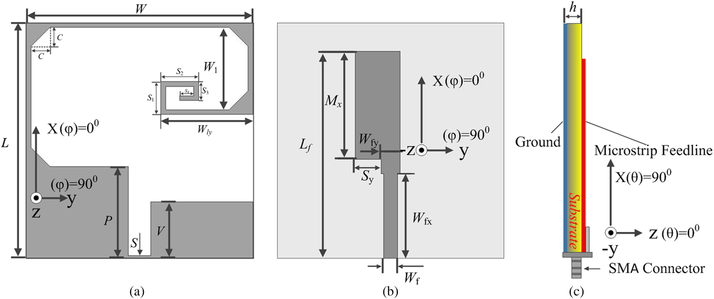
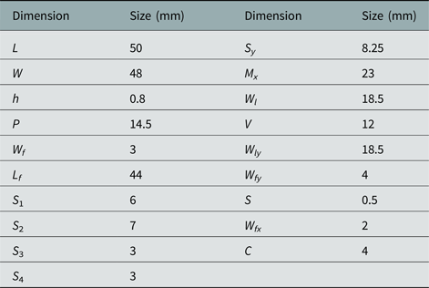
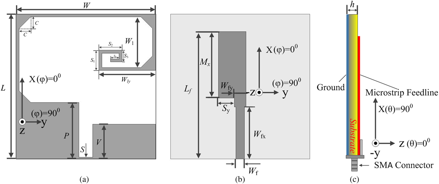
The geometry of the proposed microstrip-fed antenna is depicted in Figs 1(a)–1(c). The proposed antenna is printed on a FR4 substrate with a dielectric constant of 4.4, loss tangent of 0.02, and dimension of W × L × h. Based on the structure of Ant. I II III, an asymmetric ground plane with monofilar spiral stub is introduced to excite broadband CP operation. To enhance the impedance matching, a gradually changing resistance structure is employed on the basis of asymmetric ground and asymmetric microstrip. Then broadband CP could be obtained with two adjacent CP modes combined together by adjusting the size of the asymmetric microstrip and length of the monofilar spiral stub connected to the ground plane. On the other hand, with four isosceles triangle stubs added at the corner of the monofilar spiral stub, the bandwidth of the AR has been efficiently widened with little impact on the resonate frequency. According to the simulation studies from ANSYS HFSS 13, to achieve a maximum 3 dB AR bandwidth while keeping the return loss better than 10 dB, the dimensions of the inverted-L strip, microstrip feed line, and asymmetric ground plane were optimized which are shown in detail in Table 1.
Structure of the proposed microstrip-fed planar monopole antenna and its prototype. (a) Top view. (b) Bottom view. (c) Side view.
Optimal dimensions of the proposed antenna

Effect of inverted-L strips and asymmetric ground plane
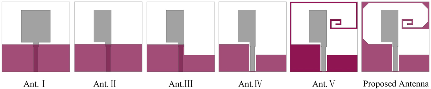
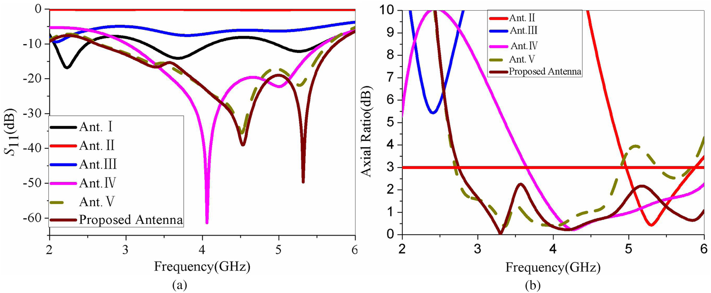
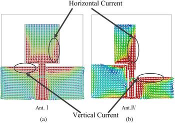
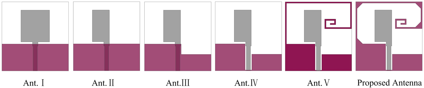
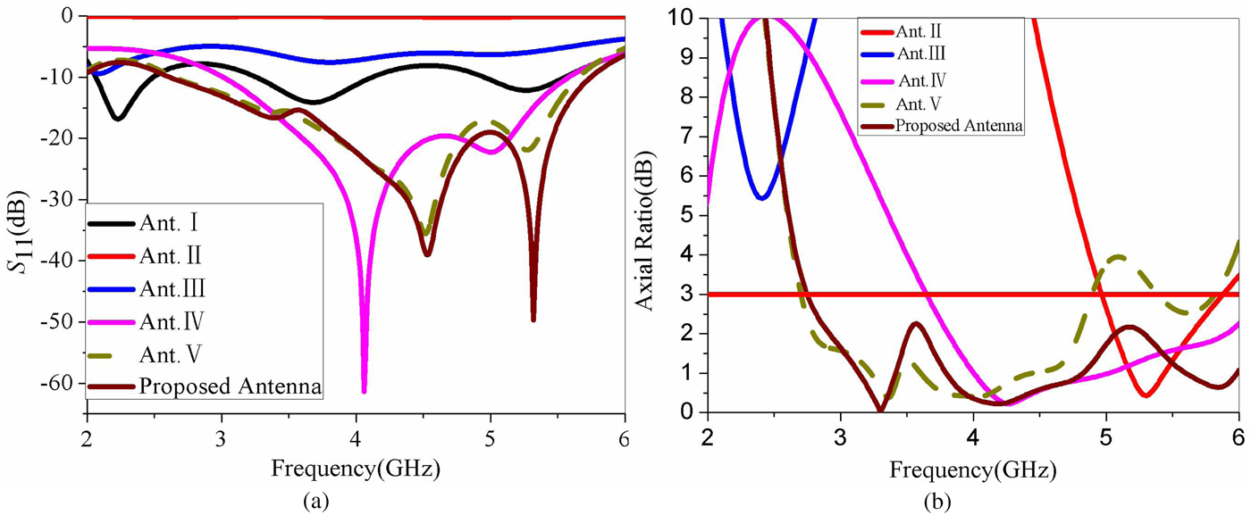
As depicted in Fig. 2, six prototypes (Ant. I to Proposed Antenna) are displayed to understand the operating principle of the proposed antenna. The performance of S 11 and AR in Ant. I to Proposed Antenna is also compared in Fig. 3. It is generally known that due to the weak radiation in horizontal or vertical direction, CP radiation is difficult to be generated for a traditional monopole which can be explained by the surface current vectors in Fig. 4. Obviously, as displayed in Fig. 4(a), the horizontal direction of the surface current vectors of two ground planes is opposite, which means that due to the small horizontal components, vertical polarized radiation could be achieved with the horizontal surface current vectors counteracted. So, linear polarization is produced with a large value of AR shown in Fig. 3 in Antenna I.
Six prototypes of the monopole antenna.
Simulated reflection coefficients and axial ratio in comparison with different monopole antennas. (a) S 11. (b) AR.
Surface current vector distribution. (a) Ant. I at 3.3 GHz. (b) Ant. IV at 4.3 GHz.

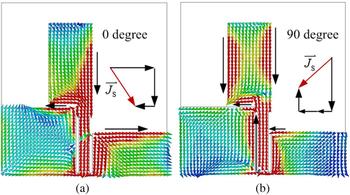
Such, to achieve wideband AR, the direction of electric currents in the patch and ground plane is modified by protruding inverted L-shaped strip and inverted L-shaped slot near the top edges of patch and ground plane, respectively. The size of the asymmetric ground plane is chosen to be λ g/4 at the lowest frequency of the CP band. The quarter wave resonant path of the inverted-L strip monopole contributes to the first two resonances at 4.03 and 5.02 GHz, respectively. The antenna (Antenna IV) shows good CP characteristics with an AR bandwidth of 2.41 GHz (3.68–6.09 GHz), centered at 4.89 GHz. A CP mode (f 1) occurs at 4.27 GHz. The surface current distribution at f 1, for two phase variations ωt = 0° and ωt = 90°, is shown in Figs. 5(a) and 5(b), respectively. The arrow heads in the figure indicate the direction of maximum surface currents and they are observed to be localized in the inverted-L strip and the edge of the inverted-L slot regions of the prototype. Along with inverted-L strip, the ground plane also contributes to CP radiation due to the asymmetry. During ωt = 0°, the combination of current vectors in the inverted-L strip region of the patch and in the asymmetric ground plane gives a tilted current directed toward φ = −45° with respect to the + x-axis. The method of composite vector analysis is used to determine the sense of rotation of the resultant current vector, shown as  ${\mathop{J}\limits^{\rightharpoonup}}_s$ in the diagram. During ωt = 90°, strong surface currents exist in both the inverted-L strip and the edge of the inverted-L slot region. This means that the strip and slot complement each other. The resultant current vector in this case is directed toward φ = −135° with respect to the + x-axis. For ωt = 180° and ωt = 270°, the currents are equal in amplitude but opposite in phase to that of ωt = 0° and ωt = 90°, respectively. This clockwise movement of current vector (
 ${\mathop{J}\limits^{\rightharpoonup}}_s$) shows that Antenna IV radiates left-handed circular polarization (LHCP) waves in the far field. But the antenna could not possess broadband CP property despite the well-matched impendence. In order to achieve a wider CP operation, spiral stubs structure is used to generate circular polarization. Such, another CP mode (f 2) occurs at 3.3 GHz. Therefore, broadband AR is achieved by overlapping two CP states as in [Reference Hu, Ding, Ni and Cao13, Reference Kumar and Harish14]. The CP modes in the AR plot of the proposed antenna (Proposed Antenna) occur at 3.3 and 4.2 GHz, which are close to f 1 and f 2, respectively. Therefore, a broad CP performance is obtained by the spiral stub yielded by symmetric microstrip with a gradual changing structure, which could match well with the impendence band mode, as revealed from Fig. 3; and the 3 dB AR bandwidth is wholly covered by the improved impedance matching in the whole band. Therefore, it can be concluded that from the comparison of results between the four antennas, the Proposed Antenna performs a wider impendence matching and wider CP radiation.
Surface current vector distribution at 4.3 GHz in Ant. IV. (a) 0° (b) 90°.

The mechanism of adding inverted-L strips with spiral
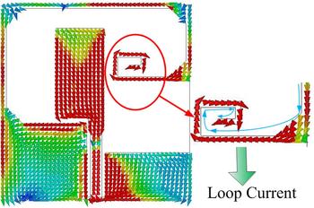
As known, a CP radiation requires two orthogonal electric far fields with equal amplitude and quadrature phase difference. On one hand, the original non-monofilar spiral stub structure would provide an equivalent magnetic current at the inverted-L strip patch, which forms a vertical polarization in the horizontal plane [Reference Bisharat, Liao and Xue21]. The equivalent magnetic current is related to the radial electric current on the patch. On the other hand, adding the inverted-L strips with spiral slits connected at the edge of the modified ground plane would create a circumferential current loop. In Fig. 6, it is shown that there is an added clockwise current on the inverted-L strips with spiral on the top plane. The added clockwise currents on the monofilar spiral stub would generate an overall loop current. The loop current would then excite a horizontal polarization in the horizontal plane. By carefully tuning the dimensional parameters, a balance between the horizontal and vertical polarizations can be achieved. With the addition of the inherent phase difference of the two linear polarizations, a CP radiation can therefore be obtained in the horizontal plane.
Surface current distributions simulated from HFSS at 4.3 GHz of a sector portion on monofilar spiral stub in Antenna V.

Parametric study and discussion
To achieve good performance for broadband CP operation, different parameters adjustments have been simulated and then analyzed, where different impacts on the performance of the antenna will be found, so that the optimized dimensions of the monopole antenna could be obtained. So a slight modification of the antenna parameters for CP radiation should be required to achieve the desired AR bandwidth and impedance matching. Meanwhile, It is shown that a CP radiation mainly depends on dimensions of the inverted-L strip, height of the ground plane, and length of the monofilar spiral stub, which have been shown in Figs 7(a) and 7(b). So the dimensions of the inverted-L strip, height of the ground plane, and length of the monofilar spiral stub are specifically analyzed and then simulated. The other optimized dimensions of parameters are listed in Table 1.
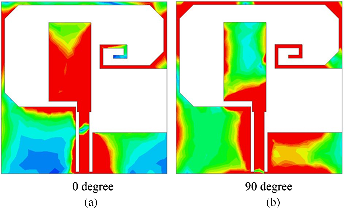
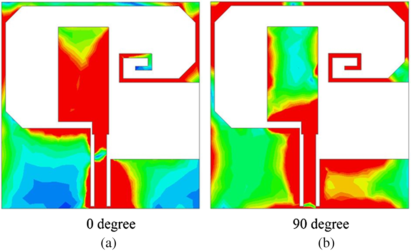
Surface current distributions of the proposed antenna at 3.3 GHz. (a) 0°. (b) 90°.
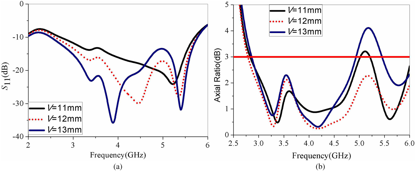
The effects of the V
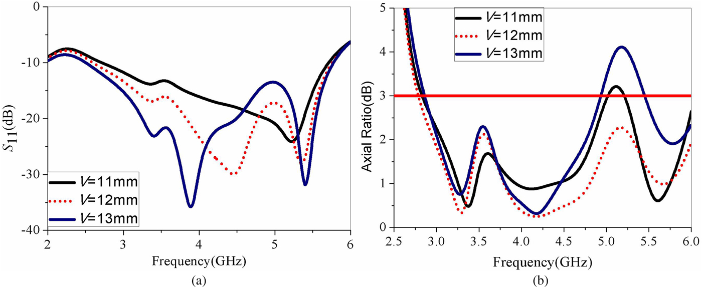
As demonstrated in Figs. 8(a) and 8(b), the variations of V have great effects on the impedance operation. As V increased, the center frequency of S 11 curves tends to shift lower with little impact on bandwidth. On the other hand, V plays an important role on CP property of the antenna. As V increases, the AR width is improved with little effects on the center frequency of AR curves. While, as V > 12 mm, the CP performance worsens rapidly instead of the bandwidth of the AR increases as V < 12 mm. Thus, V is selected as 12 mm.
Effect of V on antenna performance. (a) S 11. (b) AR.
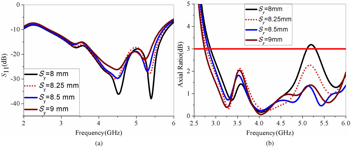
The effects of the S y
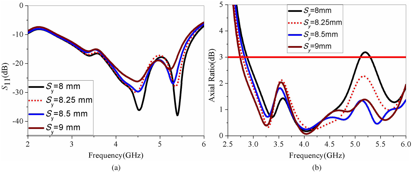
As shown in Figs. 9(a) and 9(b), the length of inverted-L strip, S y, is investigated to find its effect on the antenna's performance. As demonstrated in the figures, the variations of S y have great effects on the impedance operation. As S y increased, the upper resonant frequency of S 11 curves tends to shift lower with little impact on the lower resonant frequency. On the other hand, S y plays an important role on CP property of the antenna. As observed in figures, wider AR bandwidth is observed to improve as S y varied from 8 to 9 mm with the lower resonant frequency shifted toward lower frequency. So, to achieve a good performance in both the reflection coefficients and the ARs, a tradeoff has to be made when selecting S y. In the current prototype of the proposed antenna, S y is set to be 8.25 mm in the experimental verification.
Effect of S y on antenna performance. (a) S 11. (b) AR.
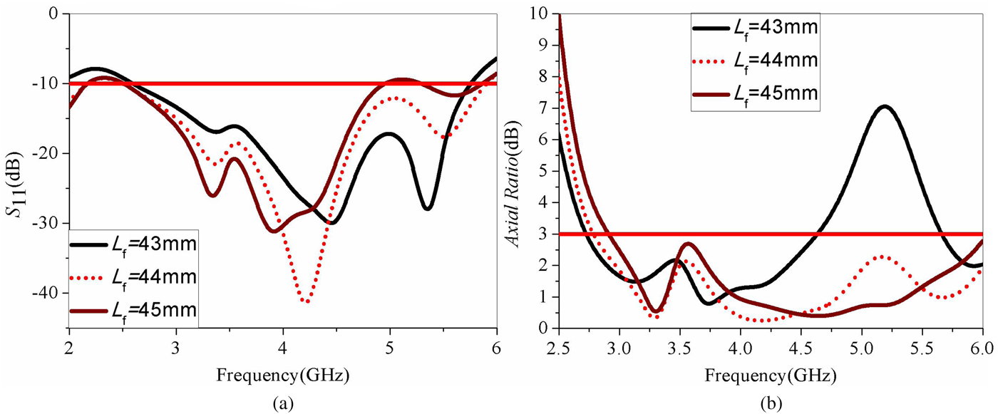
The effects of the L f
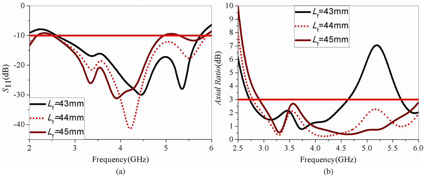
The S 11 and AR curves for various L f are displayed in Figs. 10(a) and 10(b). As observed in the figures, better impedance matching is exhibited, and also the center frequency of the reflection coefficient is observed to decrease as L f varied from 43 to 45 mm with the lower resonant frequency shifted toward lower frequency. Meanwhile, it is shown that L f has great effect on the AR. As L f increases, the AR width is improved with little effect on the center frequency of AR curves. Simulation and analysis show that the best impedance and AR property occurred for 44 mm.
Effect of L f on antenna performance. (a) S 11. (b) AR.
Circular polarization mechanism
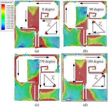
As illustrated in Figs 11(a)–11(d), the simulated surface current vector distribution of the patches at 3.3 GHz for four different time phase instants, from 0 to 270° respectively, with an interval of 90° is depicted. It could be observed that, as time varies, the surface current vectors  ${\mathop{J}\limits^{\rightharpoonup}}_s$ rotate mainly clockwise, which means that the LHCP operation is produced at 3.3 GHz. While, as noticed, this LHCP operation is achieved at the direction of z > 0, which is located at the upper half space. Instead, a right-handed circular polarization (RHCP) operation would be observed at the z < 0 direction of the other half space.
Surface current vector distribution at 3.3 GHz.

Simulation and measurement results
As listed in Table 1, all the dimensions of the proposed antenna have been optimized according to the results of numerical analysis.
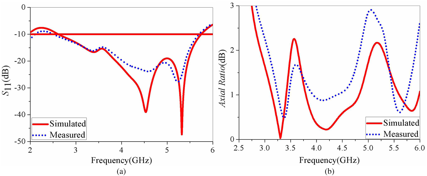
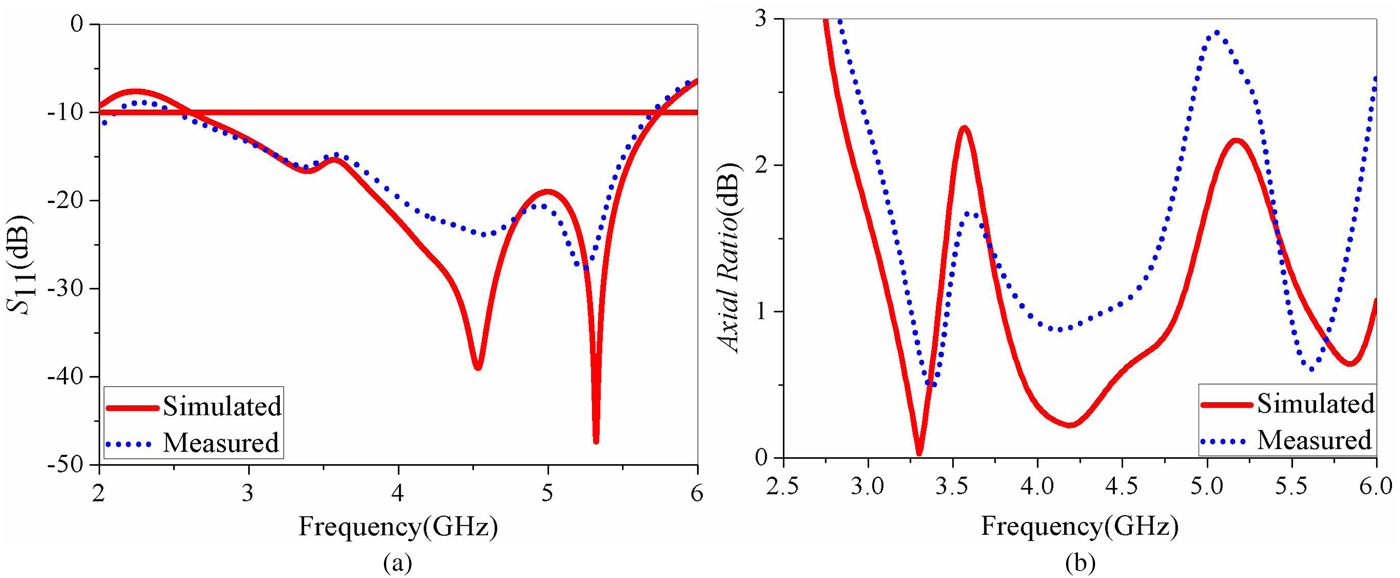
The proposed antenna was initially simulated using HFSS and then fabricated with the optimized dimensions as shown in Fig. 1(d) with a photograph. The RHCP and LHCP radiation patterns and AR were measured in an anechoic chamber using a standard gain horn antenna as a reference and computed using data from their far-field components and using formulae from the literature [Reference Tefiku and Grimes22]. Simulated and measured results of reflection coefficients and ARs of the proposed antenna are illustrated in Figs 12(a) and 12(b). As can be seen from the figures, the measured and simulated impedance bandwidths are 76.2% (2.6–5.8 GHz). It is shown that the measured CP bandwidths are 72.9% ranging from 2.7 to 5.8 GHz, centered at 4.25 GHz, which could completely cover the Wimax (3.3–3.8 GHz) band. An excellent agreement is observed between the simulated and measured |S 11| and AR curves except for some mismatches owing to the poor quality of the Sub-Miniature-A (SMA) connector used and fabrication tolerance during measurements [Reference IGWE23, Reference Toh, Cahill and Fusco24]. Moreover, as observed in figures, CP bands are completely covered by its impedance bands.
Simulated and measured reflection coefficients and axial ratio of the proposed antenna. (a) S 11. (b) AR.
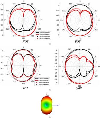
As shown in Fig. 13, the numerical and experimental radiation patterns of the proposed CP asymmetric microstrip antenna at 3.3 and 4.3 GHz for the XOZ and YOZ planes are plotted, respectively. When operating at the lower frequency, the proposed antenna radiates in slot-like patterns for RHCP/LHCP polarization, while also at the upper frequency [Reference Wang and Hang25, Reference Pazoki, Kiaee, Naseri, Moghadas, Oraizi and Mousavi26].
Simulated and measured radiation patterns in different planes and three-dimensional (3D) radiation patterns. (a) 3.3 GHz. (b) 4.3 GHz. (b) 3D radiation patterns at 4.3 GHz.

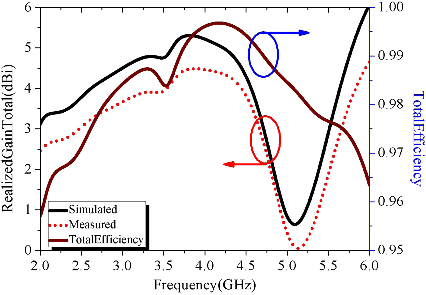
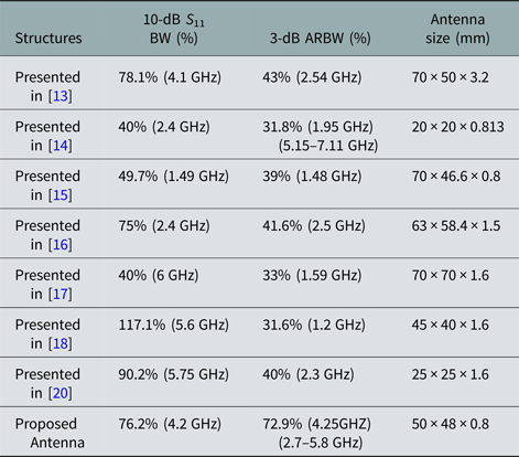
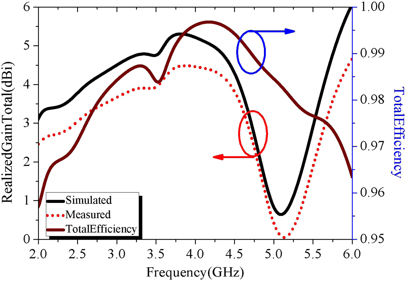
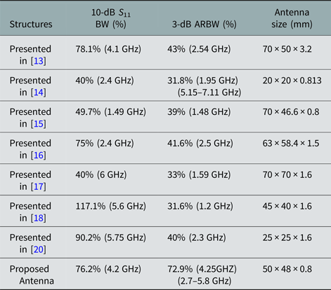
In addition, from Figs 13(a) and 13(b), we can see that compared with the measured radiation patterns in the E-plane (XZ plane, φ = 0°) and the H-plane (YZ plane, φ = 90°), the simulated far-field radiation patterns of the antenna are validated. Clearly, LHCP and RHCP patterns, which the proposed antenna are radiating, depend on whether +Z direction (upper hemisphere) or –Z direction (lower hemisphere) you observed in; and from the figure, it can be observed apparently that the simulated and measured patterns agree well with each other, thus proving the performance of the antenna designed. Meanwhile, peak gains measured are 5.6 dB, which is shown in Fig. 14. Moreover, a better gain performance and radiation efficiency is characterized at CP bandwidths in spite of the deterioration out of the CP bandwidth. As listed in Table 2, compared with published works, a more compact, wider bandwith circularly polarized antenna was achieved in this paper.
Simulated and measured gain and efficiency of the proposed antenna.
Comparison of different structures presented in literatures
Conclusions
In this paper, a novel compact broadband CP asymmetric microstrip antenna is proposed. A broad 3 dB AR bandwidth could be produced by combining asymmetric microstrip and monofilar spiral stub with two adjacent CP modes coupled together. Simulated results show that the proposed antenna could achieve a 10 dB impedance bandwidth of 76.2% (2.6–5.8 GHz) and an AR bandwidth of 72.9% GHz (2.7–5.8 GHz), which have a good agreement with measured data. Therefore, the proposed antenna is suitable for circular polarization applications in Wimax (3.3–3.8 GHz) bands. Simulated and measured results have shown that a simpler structure, broadband AR, wider impedance matching, and a more compact size could be obtained compared with published antenna recently.
Acknowledgement
This work is supported by the National Natural Science Foundation of China (Grant No. 61372034) and the Aeronautical Science Foundation of China (Grant No. 20140196001). The authors would like to thank the China North Electronic Engineering Research Institute for the fabrication.
 Cheng-Zhong Lv was born in Beijing, China. He received the bachelor and master degrees from Air Force Engineering University (AFEU), Xi'an, China, in 2011 and 2013, respectively. He is currently pursuing the Ph.D. degree in Electrical Science and Technology, Air Force Engineering University (AFEU), Xi'an, China. His research 389 interests include dielectric resonator antenna, antenna in package, and energy harvesting. E-mail address: 1101596177@qq.com.
 Lu-Chun Yang was born in Jiangxi, China, in 1990. She received the B.S. degree from Xi'an University of Posts & Telecommunications, Xi'an, China, in 2012, and M.S. degree from Southeastern University, Nanjing, China, in 2015, respectively. Her research interests include telecommunication engineering and integrated circuit design. Now she works for China Mobile (Shenzhen) Limited as a software Engineer. E-mail address: 1063383077@qq.com.