Introduction
In vivo dosimetry is a tool of independent dose verification and quality assurance in radiotherapy which may be helpful not only to improve the quality of procedure but also the treatment.Reference Hewlett, Duggan, Bazley and Kron1, Reference Blyth, McLeod and Thwaites2 Being the first use of Isorad diode in radiation therapy unit, for in vivo dosimetry, a list of correction factors were calculated including certain preliminary tests, based upon this data the accuracy of in vivo dose results were determined.Reference Islam and Muhammad3 This dosimetry is a requirement of a busy radiotherapy department in order to formulate action levels for radiation treatment of patients.Reference Appleyard, Ball and Hughes4–Reference Fontenla, Yaparpalvi, Chui and Briot6 Diode dosimeter with its electrometer generates signal in order to record the dose delivered to human phantom/patient.Reference Rosenfeld7–Reference Lanson, Essers, Meijer, Minken, Uiterwaal and Mijnheer13
This study was vital from clinical and medical physics point of view in our radiotherapy department. The causes of errors in the first radiation treatment of patient are monitored which may be simulator, treatment planning system (TPS), record and verify system, radiation treatment unit (cobalt-60). In the treatment plans on human phantom, reference points were marked at the beam entrance points. The doses at reference points in phantom were verified by using semiconductor diode. The entrance dose measurements verified our pre-simulation and simulation work (definition of target volume, target volume localisation), treatment planning (choice of beam arrangement, beam modification, dose specification), treatment machine, implementation and verification of treatment plans.Reference Dobbs, Barrett and Ash14, 15
TPS-contained beam data usually available in the form of percentage depth dose, tissue maximum ratio and tissue phantom ratio. The correction factors for geometric parameter, e.g. source to surface distance (SSD), field sizes, presence of wedges and trays were applied in order to get correct values of diode signal. This incorrection is caused by change in dose rate, attenuation of beam energy and temperature variation.Reference Khan16, Reference Huyskens, Bogaerts and Verstraete17
Materials and methods
ATOM Adult male human phantom (Model 701-D, Computerized imaging reference systems, Inc., Norfolk, VA, USA) having sectional design was used. Skeletal anatomy contained average bone tissue composition, spinal cord and cartilage substitutes. The electrometer used for patient dose monitoring was patient dose monitor (Model No.37-721, Nuclear Associates, Division of Victoreen, Carliplace, NY, USA). It was a dual channel diode dosimetry system. Isorad diode (Sun Nuclear Corporation, Melbourne, Australia) of n-type was used for the verification of treatment plans doses on cobalt-60 machine. The configuration of Isorad diode was cylindrical. The pre-calculated correction factors (CF) for this diode were CFtray, CFFS, CFSSD, CFangle, CFblock having values 1·001, 1·001, 0·997, 1·006 and 0·990, respectively. CFwedge were 1·024, 1·030 and 1·038 for 30°, 45° and 60° wedges, respectively. CFFS, CFSSD, CFangle were used frequently in our study with open beams for treatment planning of brain, larynx, nasopharynx, bladder, prostate and lung cases on human phantom. The plastic to water conversion factor (K pl) was 1·006. The diode calibration factor (F cal) was 0·989. The fields involving tray, wedge and block are more complex, therefore they have not been considered while checking accuracy of dose delivery in phantom.
TPS, MULTIDATA Decision Support System 2.5, was used for generating treatment plans based on non-isocentric technique on human phantom. The transverse sectional images of phantom anatomy were available with number (1, 2, 3, etc.) having slice thickness of 25 mm just like computerised tomography images. A hypothetical tumour was marked on a particular slice. Five slices were digitised keeping selected transverse section of slice in the centre so that effect of scattered beam photons may also be included in our calculated and measured data. During digitisation phantom left was marked on left and phantom right was marked as right.
The treatment plan was to be verified at cobalt unit. Therefore cobalt-60 beams were applied on the tumour site and treatment plan was prepared for certain prescribed dose (100 or 200 cGy). Hot spots are produced very frequently due to cobalt-60 beams because of large beam divergence. Reference points were marked 5 mm below the surface of phantom while preparation of treatment plan at Multidata TPS.
After getting expected values with TPS, they were practically measured and dose was calculated using the following generalised formula.
 $${\rm{Dose}}\, = \,{\rm{Diode}}\ \;{\rm{reading}}\,\times \,{{K}_{{\rm{Pl}}}}\,\times \,{{F}_{{\rm{cal}}}}\,\times \,{\rm{CF}}\eqno\rm$$
In treatment plans, in-homogeneity correction was applied for photon as well as for electrons.
To implement treatment plans based upon SSD technique, phantom was taken to simulation room on Shimadzu simulator (Shimadzu Corporation, Japan) for marking lasers in order to make longitudinal and transverse alignment of phantom and to have reference marks for field size. The phantom position was reproduced in cobalt unit for irradiation purposes and to quantify doses at the reference points in phantom.
For nasopharynx case, slice number 5, one anterior and two lateral beams were used for treatment planning each were having field size 10 × 5 cm2. Lung case, slice number 19, antero-posterior (AP)/postero-anterior (PA) beams were applied in treatment plan, each having field size 10 × 14 cm2. For bladder case, slice number 34, four beams were applied, two AP/PA beams 10 × 10 cm2, two were lateral beams 10 × 8 cm2 at 90° (Left lateral), and 270° (Right lateral). For prostrate case, slice number 35, four beams were applied, two AP/PA having field size of 10 × 8 cm2, two were lateral beams 6 × 6 cm2 inclined at 90° (left lateral), 270° (right lateral). For brain case, slice number 2, one anterior 10 × 8 cm2 and two lateral beams 6 × 6 cm2 inclined at 90° (left lateral), 270° (right lateral) beams were applied. For larynx case, slice number 9, one beam 10 × 6 cm2 is inclined at 300° on the right anterior side of phantom whereas the other beam 10 × 6 cm2 is inclined at 60° on the left anterior side of phantom. As stated above, slice number represents the location of slice in the phantom anatomy.
Results
The implementation of treatment plan for nasopharynx has been shown in Table 1. The individual contribution of beams at all reference points marked on the treatment plan:
 $${\rm{Dose}}\, = \,{\rm{Diode}}\;{\rm{reading}}\,\times \,{{K}_{{\rm{pl}}}}\,\times \,{{F}_{{\rm{cal}}}}\,\times \,{\rm{C}}{{{\rm{F}}}_{{\rm{FS}}}}\eqno\rm$$
Treatment plan implementation on nasopharynx

Abbreviation: TPS, treatment planning system.
The dose measured at points X2, X3, and X4 varies with expected values in the range 1·44–3·89%.
Data for lung case in human phantom are presented in Table 2. The percentage variation in expected and measured doses at the points marked on treatment plan is in the range 0·29–0·54%. The dose has been measured by using Equation (2).
Treatment plan implementation on lung

Abbreviation: TPS, treatment planning system.
Box technique (four beams) was used for bladder case in human phantom. The variation in dose calculated with diode at reference point X2 on the anterior side is 6·18%.
The individual contribution of beams for a particular reference point in Table 3 has been obtained by applying following Equation (3):
 $${\rm{Dose}}\, = \,{\rm{Diode}}\;{\rm{reading}}\,\times \,{{K}_{{\rm{pl}}}}\,\times \,{{F}_{{\rm{cal}}}}\,\times \,{\rm{C}}{{{\rm{F}}}_{\rm{S}}}\eqno\rm$$
Treatment plan implementation on bladder

Abbreviation: TPS, treatment planning system.
Correction factors include only field size correction factor CFFS and angle correction factor CFangle. CFFS was applied in beams 2 and 3 for reference points X2, X3, X4 and X5. However, for beams 1 and 4, angle correction factor was used for reference point X2 along with plastic to water conversion factor and diode calibration factor.
Four beams (box technique) were used to treat prostrate tumour in human phantom. The data are presented in Table 4. The verification results of box technique for prostate indicated a variation of 5·16%, 4·89% for X2, X5 reference points in treatment plan. However, the doses at reference points X3 and X4 are less deviated from expected value.
Measurement of doses at various reference points of prostate treatment plan
Abbreviation: TPS, treatment planning system.
The dose calculation of each beam contribution for a particular reference point is given according to Equation (3). For dose at reference point X2, X3 and X4, CFS include only one correction factor of field size (CFFS). At reference point X5, CFS include field size and angle correction factor because on the posterior side of phantom diode was tilted in the downward direction.
The data collected for the case of brain is presented in Table 5. For reference points at X2, X3, and X4 in the treatment plan of brain, the difference between expected and measured doses were 4·90%, 4·06%, 0·33%.
Treatment plan implementation on brain

Abbreviation: TPS, treatment planning system.
The dose calculation in Table 5 of each beam contribution for a particular reference point is given according to Equation (3); CFS include correction factors because of field size and angle. Angle correction factor was used owing to round surface of head region where the diode was positioned in slightly tilted position.
The data of larynx plan are presented in Table 6. The appearance of such a value of variation at reference points in Table 6 was expected because it was rather a difficult case to handle with SSD technique. The tumour was involving a highly irregular area on the lower mandible portion of human phantom. The position and placement of diode over such a site was a difficult job not only for setting SSD rather placing the diode well pasted there during irradiation. This raised the level of variation up to 5·58–6·74% in that region. The dose calculation of each beam contribution for a particular reference point in case of larynx is according to Equation (3). CFS includes correction factors because of field size and angle. Oblique beams have been used for this treatment.
Treatment plan implementation on larynx

Abbreviation: TPS, treatment planning system.
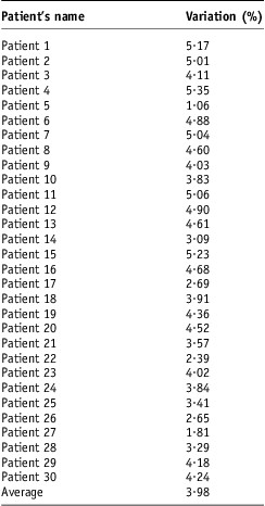
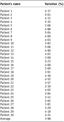
At the end of our study patient doses of some patients were monitored. The single point doses already calculated for 30 real patients (palliative cases based on single beams) were verified on cobalt unit for entrance dose measurements which caused percentage variation in dose delivery 1·05–5·35% (average 3·98%) as depicted in Table 7.
Patient dosimetry data
Discussion
From the literature,Reference Blyth, McLeod and Thwaites2 overall entrance dose delivery to patients with diode dosimetry system deviated by more than 5·00% from expected was 3·00% in case of head and neck malignancies. In case of our phantom study, nasopharynx treatment plan, the positioning of diode has given inadequate (less) dose evaluation at the exit points of beams 2 and 3 because of absence of back pointer at this unit, so setup error is the main cause of variation (average 2·483%). The dose delivery has been lower than 5·00% threshold by 1·11% because of absence of movement and real time factors affecting dose delivery.
In the verification of dose delivery for larynx case, the main problem was small uplift in diode position because of location for placement of diode leading of poor fixation. This created an air gap between phantom surface and diode because of poor fixation of diode, thus created a variation of 5·58–6·74% (average 6·16%). The difference between measured and expected dose delivery in both beams was above the 5·00% threshold by 0·58–1·74% because of irregularity in the contour of phantom surface.
The position and placement of diode over larynx was difficult not only for setting SSD rather placing the diode well pasted there during irradiation. Including larynx and nasopharynx cases, the average result was found 3·95% with larynx being the major contributor of this variation making the overall dose delivery accuracy 1·05% less than our 5% threshold. With reference to literature,Reference Appleyard, Ball and Hughes4 the threshold of dose accuracy is set at 4%. Head and neck cases produce doses in the range of 0·35 ± 2·20%.
For lung case, the percentage variation in dose at reference points has been very small 0·29–0·54% as tabulated in Table 2. The cause of such a low variation was relatively easy implementation of treatment plan on cobalt unit. On the posterior side (beam 2) of phantom net wire between diode and phantom created the problem of fixing the diode. But it was transparent for radiations so almost no variation in dose was expected because of net wire. As per literature,Reference Appleyard, Ball and Hughes4 the cases of intra-thoracic region gave result of −0·01 ± 2·75%. In case of phantom, the results are quite good because of absence of real patient-related factors as observed the same in case of head and neck cases stated above.
In bladder case, the difference in measured and expected dose at point X2, 6·18%, is mainly because of inadequate measurement of exit dose from beam 4 (setup limitation). This point (X2) was on the steep surface of human phantom, thus making the diode angular with respect to gantry axis. Even multiplication with angle correction factor (CFangle) could not give accurate result. A part of diode sensitive area was above and a part was lower than this point X2. Whereas variation of 6·00% in dose at reference point X5 was because of positioning of diode as well as poor fixation at this point. The contribution of exit dose from beam 1 is smaller than expected. It was also because of improper and limited placement of diode over the posterior surface of slice.
It was difficult to position diode exactly on the posterior side of human phantom because of presence of net wire in patient table where once the data had been taken for beam 4.
In prostate case, much of the variation in dose at point X5 (4·89%) is because of uncertain positioning of diode at posterior side of slice 35. This position is also angular as well. This angle caused loose fixation of diode with a small gap of air in-between phantom and diode surfaces. At point X2, variation in dose (5·16%) is due to less contribution of dose from beam 4. The doses at reference points X3 and X4 were less affected by diode positioning as compared to doses at other two reference points (X2 and X5). With reference to literature, abdomino-pelvic cases should have dose delivery accuracy as 0·52 ± 2·75%. It is clearly deviated in case of beams falling on the curved contours (surfaces) of human phantom where the exit doses are difficult to measure because of the absence of back pointer on machine.
LiteratureReference Appleyard, Ball and Hughes4 allows error larger than 5·00% in dose for 1% of patient treatments with sophisticated in vivo dosimetry systems and 3–10% error without verification system.
For brain case, the cause of variation in dose at reference point X2 in Table 5 (at the entrance of beam 2) was the uncertainty in diode placement.
Similarly the dose at point X3 (at the entrance of beam 3) has a variation of 4·06% because of improper positioning of diode at the entrance points of beams 1 and 2. However, the dose at reference point X4 is accurate because doses were accurate at the entrance points of beams 2 and 3. Thus the variation (0·33–4·90%) in brain case is because of setup limitations. On cobalt machine the minimum value of field size was 5 × 5 cm2.
In phantom study, where patient-related errors are minimised, the dose delivery is accurate on the average up to 3·15%, this error even rise up to 3·98% (26·35% higher) in real patients. This increase is expected in patients because of the movement of planning target volume because of breathing/heart beat, mechanical errors in machine, patient couch, quality assurance (QA)-related issues. This dosimetry system not only verifies doses planned on TPS rather provide easiness of working for such verification.Reference Rosenfeld7, Reference Alecu, Loomis, Alecu and Ochran9
So measurement of correction factors, calibration factors and conversion factors and their inclusion in diode dose is not sufficient to measure accurate dose delivery to patient rather there are other real patient-related factors like.
Conclusion
On human phantom, variation in dose for various treatment plans was from 0·29% to 6.74% (Average 3·15%). The data of dose delivery for 30 real patients (palliative cases based on single beams) with the difference of 1·05–5·35% (average 3·98%) between expected and measured values. The average dose in real patients is 26·35% higher than human phantom indicating the role of factors other than correction factors, calibration factors and conversion factors. Thus in vivo dosimetry with diode is unable to give accurate results because of real patient-related factors, which we need to calculate before actual in vivo diode dosimetry.
Acknowledgement
Work attributed: Karachi Institute of Nuclear Medicine & Radiotherapy (KIRAN), opposite Rizvia Society, Karachi.