1 Introduction
The interaction of vortical structures with solid boundaries is a very complicated fluid dynamic problem that has been studied for a long time (Rockwell Reference Rockwell1998); its importance stems from its occurrence in many engineering applications. This kind of interaction is associated with unsteady loads on solid walls that cause structural vibration, noise emission and efficiency loss. Typical examples where these flows appear are the rotor–rotor or rotor–wing configurations in the marine, aeronautical and renewable energy fields.
In the case of marine vehicles, the propeller–rudder system is central to the success of a new design, it being responsible for propulsive efficiency, vibrations, noise emission and control. Flows around these configurations were extensively investigated in terms of global loads, in order to develop and improve simplified mathematical models for the prediction of vessels manoeuvrability and for the design of rudders (Molland & Turnock Reference Molland and Turnock2006). The demand for reliable models increased with the increase of operative speed (achieved in practice with higher propeller loadings) and by the stricter requirements imposed by international regulations.
Similar arrangements and problems appear for airplanes and for helicopters. In the former case (closer to marine rudder–propeller arrangements), recent studies were particularly aimed to inspect the impact of propeller–wing configuration on the overall performance of the vehicle (Veldhuis Reference Veldhuis2005). The latter case is instead richer in peculiar phenomena, such as the interaction of a blade with the tip vortex of the preceding blade, interactions between the vortex system from the main rotor with those of the tail rotor and the fuselage and so on. All these flow details contribute to structural fatigue, impulsive and broadband noise, manoeuvring and control; therefore, plenty of experimental and numerical investigations have been dedicated to them (Marshall Reference Marshall1994; Marshall & Yalamanchili Reference Marshall and Yalamanchili1994; Kim & Komerath Reference Kim and Komerath1995; Marshall & Grant Reference Marshall and Grant1996; Marshall & Krishnamoorthy Reference Marshall and Krishnamoorthy1997; Krishnamoorthy & Marshall Reference Krishnamoorthy and Marshall1998; Rockwell Reference Rockwell1998; Krishnamoorthy, Gossler & Marshall Reference Krishnamoorthy, Gossler and Marshall1999; Marshall Reference Marshall2002; Liu & Marshall Reference Liu and Marshall2004; Filippone & Afgan Reference Filippone and Afgan2008).
To this abundance of phenomena, in the naval context cavitation is another source of great concern for noise and unsteady loading on structures, and it requires proper investigation at the design stage. An excellent review about problems related to cavitation can be found in Carlton (Reference Carlton2012).
The flow in the wake of a marine propeller and its interaction with a rudder-like shape behind it encompasses two of the most studied vortex/body interactions, i.e. an almost ‘orthogonal interaction’ of the tip vortex and the perpendicular impingement of the hub vortex (that lies in the midplane of the rudder) with the leading edge of the downstream body.
In both cases, the vortex evolution can be simplified into two different contributions: a potential interaction, with vortex deformation and possibly the onset of instability, and a viscous interaction, with mixing and exchange of vorticity with the boundary layer. The preponderance of one effect over the other depends on the physical parameters.
The orthogonal blade–vortex collision was investigated with simplified models consisting of a wing (or a cylinder) impinged by a columnar (initially rectilinear) vortex (Marshall Reference Marshall1994; Marshall & Yalamanchili Reference Marshall and Yalamanchili1994; Marshall & Grant Reference Marshall and Grant1996; Marshall & Krishnamoorthy Reference Marshall and Krishnamoorthy1997; Marshall Reference Marshall2002; Liu & Marshall Reference Liu and Marshall2004). Detailed flow visualizations (by a laser-induced fluorescence technique) highlighted that the phenomenology immediately before, during and after the impact is governed by the exchange of vorticity between the body boundary layer and the vortices impacting on it, and confirmed the onset of pressure waves (predicted theoretically by simplified models) that contribute to the destabilization of the columnar vortex during and after the interaction phase. The details of flow evolution depend on the relative magnitude of the impact velocity to the swirl velocity (the impact parameter), the relative magnitude of the axial core velocity and the swirl velocity (axial flow parameter) and the relative thickness of the body with respect to the vortex core radius (thickness parameter). All these parameters provide a ‘measure’ of the intensity for the interaction and determine the predominance of ‘potential’ over ‘viscous’ interaction.
In particular, the larger the swirling velocity (i.e. the lower the impact parameter) and the higher the thickness parameter, the sooner the vorticity ejected from the boundary layer reorganizes into secondary coherent structures. These smaller structures wrap around the primary vortex and affect its dynamics during the collapse and the subsequent interaction with the boundary layer on the body (this is usually referred to as the ‘strong vortex regime’). On the contrary, high impact parameter and low thickness parameter determine a weak interaction of the vortex with the boundary layer, with negligible vortex deformation before the impact, as usually happens during vortex ‘chopping’.
Another aspect of vortex evolution during this type of collision is the sectional area increase on the upstream side of the body surface and restriction downstream (here upstream and downstream refer to mean axial velocity direction in the vortex core), coupled with waves propagation along the vortex tube, with possible destabilization and breakdown; in particular, for low axial vortex core velocity (subcritical regime) the waves travel on both sides, whereas for higher core velocity (supercritical regime) waves appear only on the pressure side (Marshall Reference Marshall1994; Marshall & Krishnamoorthy Reference Marshall and Krishnamoorthy1997; Krishnamoorthy & Marshall Reference Krishnamoorthy and Marshall1998).
Quantitative characterization of the flow resulting from the supercritical orthogonal blade–vortex interaction was performed in Coton et al. (Reference Coton, Marshall, Galbraith and Green2004), Coton, Green & Early (Reference Coton, Green and Early2006) by means of particle image velocimetry (PIV) and laser Doppler velocimetry (LDV) techniques, with an experimental set-up consisting of a helicoidal vortex (generated by a rotating wing, i.e. a single-bladed rotor) with a wing. The experiment highlighted the marked asymmetry between the opposite walls, caused by the different impingement velocities. These experimental results provided a noticeable insight in the topological evolution of the two vortex branches.
The same physical arrangement, in the particular case of a marine propeller–rudder layout, was investigated in Felli, Camussi & Guj (Reference Felli, Camussi and Guj2009), Felli & Falchi (Reference Felli and Falchi2011) by different diagnostic techniques (flow visualizations, LDV and PIV). These experiments outlined the features of the interaction between the propeller tip vortex and the rudder, such as the penetration of the vortex at the leading edge region, the double helix instability phenomenon and the evolution of the vortex filaments in the near wake past the rudder. During this latter process, a localized production of turbulent kinetic energy and enstrophy occurs, similar to what has previously been pointed out in the case of an isolated propeller (Muscari, Di Mascio & Verzicco Reference Muscari, Di Mascio and Verzicco2013).
The investigations on perpendicular vortex–body interaction (accordingly to the terminology adopted in literature, the interaction of a streamwise vortex with a body lying perpendicularly to the current) was principally motivated by structural stability and control and performance of airplane wings. In fact, this interaction can lead to localized unsteady loads on narrow portions of the body surface, whose intensity can be amplified when the clearance is such to trigger vortex breakdown. The instabilities can appear as spiralling modes (Gordnier & Visbal Reference Gordnier and Visbal1999) and/or with the formation of dipoles (Garmann & Visbal Reference Garmann and Visbal2015), with different interaction with the boundary layer (for example, generation of hairpin-like vortices for the interactions of a vortex from a delta wing and a downstream plate (Gordnier & Visbal Reference Gordnier and Visbal1999) or flow separation (Zanotti et al. Reference Zanotti, Ermacora, Campanardi and Gibertini2014)). The resulting loading regimes may be characterized by different degrees of unsteadiness that can affect both the mean loads (Garmann & Visbal Reference Garmann and Visbal2015), as well as the amplitude and phase of higher harmonics.
As pointed out in the cited literature, vortex–body interactions are governed by the fine details of the evolution of coherent structures that need to be captured in order to characterize the flow of a rotor–wing system. Earlier attempts to simulate this problem numerically were based on vortex filaments techniques (Marshall & Krishnamoorthy Reference Marshall and Krishnamoorthy1997; Krishnamoorthy et al. Reference Krishnamoorthy, Gossler and Marshall1999) or inviscid vortex tube theories based on the plug-flow model (Marshall Reference Marshall1994; Marshall & Yalamanchili Reference Marshall and Yalamanchili1994). Although these approaches were extremely powerful to systematically inspect the principal aspects of the problem, they were limited to very simple configurations and cannot reproduce all the features of the phenomenon, in particular the viscous interaction. Navier–Stokes solvers (Gordnier & Visbal Reference Gordnier and Visbal1999; Garmann & Visbal Reference Garmann and Visbal2015) are instead potentially able to tackle the various vortex regimes and, moreover, are not restricted to simple geometry configurations or particular vortex topologies.
The present work was aimed at investigating the key features of the interaction of the vortices generated by a typical marine propeller with a rudder-like body placed downstream, for a model scale Reynolds number. In particular, the goal was to relate the vortex system evolution to pressure loading on the rudder and to clarify the reattaching mechanisms and the mutual interaction of the hub and tip vortical systems. In fact, as opposed to aeronautic rotors, the aspect ratio of marine propeller blade is low (typically
 $1.5\sim 2$
) and, therefore, the hub and tip vortices evolve close to each other; moreover, the radial variation of the blade shape generates a vorticity, shed at intermediate radial positions, whose magnitude is not negligible with respect to the previous structures, which may trigger and drive their evolution and interaction since the early phases of collision with the rudder.
The possible configurations during usual operational conditions are very different; we will focus only on the design condition, i.e. straight course, relatively high advance coefficient for the propeller (lightly loaded propeller) and rudder in neutral position. Moreover, the work is focused on vorticity dynamics and does not consider cavitation.
The analysis was carried out by an in-house solver based on a second-/fourth-order accurate finite volume discretization of the Navier–Stokes equations; the detached eddy simulation (DES) version of the Spalart–Allmaras turbulence model (Di Mascio, Muscari & Dubbioso Reference Di Mascio, Muscari and Dubbioso2014) was adopted. Of course, we are well aware that the fine details of the vortex/boundary layer interaction are lost with a DES, as it behaves like a Reynolds-averaged Navier–Stokes (RANS) model close to the walls: in these regions the results are to be intended as purely qualitative. Nevertheless, the physical parameters (loading, vortex and foil dimension, Reynolds number) are such that the evolution is dominated by the aforementioned ‘potential’ interaction, and the fine details of the mutual exchange of vorticity in the boundary layer should be of relative importance. On the other hand, given the Reynolds number that characterizes the present problem, large eddy simulation (and even more so direct numerical simulation) are out of question. At the same time, a simulation with a Reynolds number low enough to allow a wall resolved large eddy simulation (LES) would produce boundary layers and vortices whose relative dimensions would render the problem too far (in terms of thickness and impact parameter) from what is encountered in marine hydrodynamics.
The same geometry adopted in Felli & Falchi (Reference Felli and Falchi2011) was considered, namely a typical propeller–rudder layout installed on ships. However, in order to simplify the analysis and to gain a clearer view of the evolution of the tip and hub vortex systems, a single-bladed propeller was considered. This can be justified by the low propeller loading condition considered, for which previous investigations (Muscari et al. Reference Muscari, Di Mascio and Verzicco2013) proved that the mutual interaction of the tip vortices is negligible.
The evolution of the coherent structures was described by the popular
 $\unicode[STIX]{x1D706}_{2}$
-criterion (Jeong & Hussain Reference Jeong and Hussain1995); this is a commonly accepted mean for detecting shape and morphology of the leading vortex structures, destabilization processes and appearance of secondary vortex structures (as it may happen after vortex breakdown (Liepmann & Gharib Reference Liepmann and Gharib1992) and/or after vortex reconnection process (Felli & Falchi Reference Felli and Falchi2011)). In addition, other inspection procedures were adopted to correlate the dynamics of the coherent structures with the flow field, in particular, the power spectral density (PSD) of the pressure at prescribed locations on the surface of the body (Felli & Falchi Reference Felli and Falchi2011; Muscari et al.
Reference Muscari, Di Mascio and Verzicco2013).
2 Test case and computational mesh
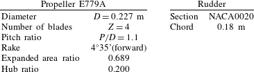
A single-bladed propeller and an infinite wing are considered; apart from the simplified propeller geometry, the layout is similar to the experimental set-up in Felli & Falchi (Reference Felli and Falchi2011); geometric characteristics are summarized in table 1.
In the physical experiment, the rudder spans the whole tunnel, in order to prevent interference with rudder tip vortices. Conversely, the geometry adopted for the simulation does not model tunnel walls, as blockage effects should not alter the basic mechanisms of vortex–body interaction. The simulations were carried out in moderate loading condition, namely at
 $J=U_{\infty }/nD=0.88$
, which is representative of the actual propeller operating condition at cruise speed.
Figure 1 shows the inertial frame of reference adopted for the numerical simulations: the
 $x$
axis, pointing downstream, coincides with the propeller axis; the
 $z$
axis is directed upward and the
 $y$
axis follows the right-hand rule. In figure 2 the reference azimuthal positions of the blade during a revolution are reported.
Inertial frame of reference.

Reference positions of the blade.

The computational domain is a streamwise cylinder with a radius of 50 propeller radii, the inflow section at
 $-$
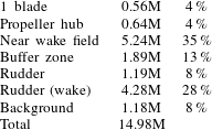
50 radii and the outflow at 50 radii. The mesh adopted in the simulations consists of 160 overlapping blocks, for a total of approximately 14.8 million volumes. A multigrid technique is exploited for convergence speed up of the inner (pseudo-time) iteration; to this aim, four nested meshes are used, each being obtained from the next finer by removing every other point along each coordinate direction.
Grid topology: propeller (a) and rudder (b).

Geometric parameters of the propeller and the rudder.

The domain around the single-bladed propeller has been divided into three different zones: propeller and near wake field, buffer region and background. The blade, the fore and the aft region of the hub were discretized by grids with O-topology, whereas the rest of the mesh is made up by concentric toroidal blocks that cover the whole computational domain. The rudder is represented by a C-topology grid. The grid around the blade (with a detail of the mesh distribution around the tip) and around the rudder in the propeller slipstream are shown, respectively, on the left and right sides of figure 3.
The mesh strategy followed for the propeller blade and the rudder is schematically represented in figure 4. In particular, the grid distribution is such that the thickness of the first cell on the wall is always below one in terms of wall units (i.e.
 $y^{+}=O(1)$
), the boundary layer being described by at least 32 cells. The cells are clustered up to 5 radii in the downstream direction, where the peculiar features of the flow must be resolved accurately (tip and hub vortices). Moreover, the portion of the rudder located in the propeller slipstream is discretized by clustering the cells approximately along the trajectory of the tip vortices (the red blocks in figure 3
b) in order to capture the details of the interaction of the primary vortex and the rudder. The outer portions of the rudder are discretized by two additional blocks with a coarser mesh in order to reduce the computational cost.
Mesh details: rudder–propeller near field (a) and propeller plane (b).

Details of the cell distribution for the finest discretization are summarized in table 2.
Details of grid cell distribution.
In the numerical simulations, the rotational speed of the propeller has been kept fixed at
 $n=25~\text{r.p.s}$
. Unless otherwise specified, all quantities have been cast in non-dimensional form by using as reference values the propeller radius (
 $L_{ref}=R=0.1135~\text{m}$
), the velocity of the blade tip (
 $U_{ref}=n\unicode[STIX]{x03C0}D\backsimeq 17.83~\text{m}~\text{s}^{-1}$
) and the density of the fluid
 $(\unicode[STIX]{x1D70C}=1000~\text{kg}~\text{m}^{-3})$
, and therefore the non-dimensional period of revolution is
 $T=(1/n)(U_{ref}/L_{ref})=2\unicode[STIX]{x03C0}$
. The Reynolds number is the same as the physical experiment carried out in pure axial flow conditions, i.e.
 $Rn=U_{ref}L_{ref}/\unicode[STIX]{x1D708}=1.78\times 10^{6}$
. The time step is set to
 $\unicode[STIX]{x0394}t=T/360\backsimeq 0.01745$
, corresponding to a one degree rotation for the propeller blade, for the finer mesh simulation.
The uncertainty analysis was performed, as in Di Mascio et al. (Reference Di Mascio, Muscari and Dubbioso2014), on global quantities, following the procedure suggested in Roache (Reference Roache1997).
The results of the uncertainty analysis are summarized in table 3. Propeller loads computed on the medium grid are very close to the finer grid results, and, for the purpose of performance prediction, can be considered reliable. The numerical uncertainty of the moment on the rudder is slightly worse than the propeller loads, probably because some details of the interaction of the rudder boundary layer and propeller wake are lost with the coarsening of the grid.
Uncertainty analysis – blade and rudder loads.

3 Results
The propeller wake evolution and its interaction with the rudder is investigated following the same lines as in the authors’ other paper (Di Mascio et al. Reference Di Mascio, Muscari and Dubbioso2014); in particular, the evolution of coherent structures is described first, and then it is related to the spectral analysis of the signals recorded at representative probes located on the rudder surface.
The evolution of the vortex system can be divided into three stages: approaching phase (before the collision with the rudder), vortex–body interaction (vortex motion along the body) and convection phase (convection of tip and hub vortices in the far wake).
In order to clarify the investigation, the analysis will be split into:
-
(i) tip vortex dynamics during the approaching phase, interaction with the rudder and convection in the near wake;
-
(ii) hub vortex dynamics during the approaching phase and interaction with the body;
-
(iii) mutual interaction of tip and hub vortex during the convection phase in the middle and far wake.
3.1 Tip vortex dynamics
According to the classification in Marshall & Grant (Reference Marshall and Grant1996) and the estimates by Filippone & Afgan (Reference Filippone and Afgan2008), the geometrical and dynamical characteristic of the tip vortex for the considered loading determine a weak and subcritical quasi-orthogonal vortex–body interaction problem.
The evolution is reported in figures 5–6 during a blade revolution period represented at intervals of
 $\unicode[STIX]{x0394}\unicode[STIX]{x1D703}=60^{\circ }$
. The key aspects of the phenomenology are highlighted in the picture and described in what follows. As already said in the introduction, we underline that the fine details of the tip vortex evolution in the boundary layer region on the rudder are to be taken as purely qualitative, because the turbulence modelling tends to a RANS approach close to the walls.
Tip vortex evolution during a blade revolution. Isosurface
 $\unicode[STIX]{x1D706}_{2}=-0.2$
.

Tip vortex evolution during a blade revolution. Isosurface
 $\unicode[STIX]{x1D706}_{2}=-0.2$
.

3.1.1 Phase 1: approaching phase
It being in weak vortex regime state, the tip vortex is not affected by the rudder up to a distance
 ${\sim}0.3R$
from it, where it experiences a small wave perturbation, evidenced by oscillation of the vortex section diameter. These perturbations start from the symmetry plane and propagate upstream and downstream along the vortex tube (see the zoomed view in figure 6,
 $\unicode[STIX]{x1D703}=120^{\circ }$
). These results mirror the experimental visualizations in Felli & Falchi (Reference Felli and Falchi2011).
3.1.2 Phase 2: interaction phase
This phase is characterized by a deeply different interaction of the two branches of the tip vortex on the pressure and suction side of the rudder, where the ‘suction’ side is defined by
 $y>0$
,
 $z>0$
(and, given the symmetries of the problem, by
 $y<0$
,
 $z<0$
after a blade rotation of
 $180^{\circ }$
) and the ‘pressure’ side is
 $y<0$
,
 $z>0$
(and
 $y>0$
,
 $z<0$
).
The two branches follow different evolutions because of both a ‘viscous’ and ‘potential’ interactions with the wall. In fact, the tip vortex is obliquely oriented and convected (the blade transfers both axial and rotational momentum to the flow) with respect to the leading edge of the rudder because of geometrical and kinematic reasons, shown in the two-dimensional sketch in figure 7.
Sketch of the early interaction phase.

During the initial phases of the collision, the branch on the pressure side is both stretched and pushed towards the wall by the local incident flow due to rotation. The stretching leads to an increase of its vorticity as a consequence of section reduction, whereas the contact area with the rudder is increased by flow impingement. As sketched in figure 8, on the pressure side the vorticity in the deflected arm of the tip core is opposite to the streamwise vorticity in the boundary layer, induced by the global rotation in the propeller slipstream, while on the suction side, they have the same sign. As a result, the interaction of the tip vortex with the boundary layer of the rudder is stronger on the pressure side than on the suction side. Details of the different interaction on the two sides of the rudder can be observed in figures 5–6 (compare zoomed windows in frame
 $\unicode[STIX]{x1D703}=120^{\circ }$
with frame
 $\unicode[STIX]{x1D703}=300^{\circ }$
, or
 $\unicode[STIX]{x1D703}=240^{\circ }$
with
 $\unicode[STIX]{x1D703}=60^{\circ }$
). In particular, the frame at
 $\unicode[STIX]{x1D703}=240^{\circ }$
on the pressure side (
 $z>0$
) shows that, because of the more energetic interaction, the tip vortex breaks into smaller filaments that wrap around each other and further strengthen the process. On the suction side (
 $z<0$
), the interaction is markedly different: the deflected portion of the vortex tube does not form until a half-chord length, as clearly evidenced in the frame at
 $\unicode[STIX]{x1D703}=300^{\circ }$
. Then, the deflected arm smoothly grows toward the trailing edge of the rudder showing a weak mixing process with the rudder boundary layer (frame at
 $\unicode[STIX]{x1D703}=60^{\circ }$
).
Interaction of tip vortex with boundary layer.

Vortex image effect.

Blockage effect combined to vortex image effect.

A second ‘potential’ interaction causes the propeller slipstream to lose its axial symmetry while interacting with the rudder, as the trace of the vortex cores follow a different path on the pressure and suction side. The global evolution of the slipstream is described in figure 10 by overlapping the tip vortices at six different instants, spaced by a blade rotation of
 $60^{\circ }$
. The trace of the slipstream on the wall (dashed red line) reveals an upward displacement of the vortex tube. The principal causes of the slipstream deformation are sketched in figures 9–10 and can be synthesized in a combination of two effects. The first one is the ‘vortex image effect’ (figure 9): the zero net flow rate through the wall is equivalent to the presence of a secondary vortex, characterized by a circulation equal and opposite to the physical vortex located on the opposite side with respect to wall; the motion of the physical and mirrored vortices is due to the mutual induction. The results on the pressure and suctions areas are shown as blue arrows in figure 10. Moreover, it can be seen that on the pressure side the upward displacement is monotonic along the chord. Instead, on the suction side, the vortex moves horizontally and then upwards only after the midchord position. This behaviour can be justified by a sort of ‘blockage’ effect. In fact, when impinging on the rudder, the cross-section of the slipstream tends to increase to maintain a constant flow rate, and then it decreases because of the progressive reduction of the rudder frontal area (as evidenced by the red arrows in figure 10). Consequently, on the pressure side the ‘blockage’ effect fosters the upwards motion induced by the self-induced velocity, whereas it hinders the displacement on the suction side.
This process induces a relative spanwise shift between the two branches, as the one on the suction side is shifted towards the axis while the one on the pressure side moves outward. Moreover, the convection velocity is higher on the suction side than on the pressure side and, therefore, when the two branches approach the trailing edge, they are misaligned both vertically and longitudinally. In addition, on the suction side, the tip vortex detaches smoothly from the trailing edge with a strengthened deflected branch, while, on the pressure side, the more energetic interaction fragmented the tip vortex branch into smaller filaments strongly intermixed with the rudder boundary layer.
3.1.3 Phase 3: convection phase
The third phase of tip vortex evolution is characterized by two reconnection mechanisms: in the first, the split branches rejoin; in the second one, bridges between two consecutive coils appear.
The details of the first mechanism are visualized in figures 5–6 by the shaded chunks on the suction (red) and pressure (green) sides for
 $z<0$
(the same happens for
 $z>0$
with the two branches swapped), where the misalignment is clearly visible.
On the suction side, the tip vortex detaches from the body with a tail made of a deflected arm that increases in length because of a continuous supply of vorticity from the rudder boundary layer and is almost perpendicular to the original vortex. On the pressure side, instead, the tip vortex experiences a much less smooth interaction with the vorticity shed by the rudder past the trailing edge and it splits into smaller filament. These structures then reorganize in a larger coherent structure that tends to be oriented as the original vortex. The complete reconnection between the two filaments takes place further downstream (frame at
 $\unicode[STIX]{x1D703}=120^{\circ }$
).
The second reconnection mechanism is described in figure 11. The elements concurring to this phenomenon are the vorticity carried by the following tip vortex and the longitudinal structure of the leading tip vortex. During the downstream convection, this longitudinal structure elongates, approaching the following coil; concurrently, the vorticity on the pressure side reorganizes into a longitudinal structure and, eventually, the two vortices merge. This structure (analogous to the one observed in the interaction of two corotating rectilinear parallel vortices (Melander & Hussain Reference Melander and Hussain1988)) generates a bridge between two consecutive coils, connecting approximately the points where the vortex was cut by the rudder.
Bridging between two tip vortex coils.

3.2 Hub vortex dynamics
The hub vortex/rudder is deeply different from the tip vortex/rudder interaction, as the tip vortex impacts almost orthogonally on the body leading edge, while the hub vortex is streamlined and lies on the rudder symmetry plane and resembles the vortex/body interaction studied in Gordnier & Visbal (Reference Gordnier and Visbal1999). However, the proximity of the blade vortex sheet confers to the interaction peculiarities that are not observed for the single vortex/wing arrangement. In fact, also in the present experiment, hairpin vortices appear (resembling the
 $\unicode[STIX]{x1D6FA}$
structures observed during delta wing–plate interaction (Gordnier & Visbal Reference Gordnier and Visbal1999)); however, these structures play a fundamental role also during the downstream convection in the middle and far wake, where they drive the redistribution of vorticity within the propeller slipstream and the merging mechanism between the hub and tip vortex, as it will be shown in § 3.3. Once more, we underline that the details of the hub vorticity evolution within the rudder boundary layer are to be interpreted as only qualitative.
3.2.1 Phases 1–2: approach and travelling phase
The approach of the hub vortex and its interaction with the rudder wall is described in the sequence reported in figure 12. For clarity, the tip vortex was removed from the pictures and the frames with a phase shift of
 $\unicode[STIX]{x1D703}=180^{\circ }$
are shown together to highlight some peculiar phenomena.
Hub vortex dynamics;
 $\unicode[STIX]{x1D706}_{2}=-0.05$
.

The initial simple shape consisting of a single streamlined vortex is soon fragmented into smaller structures generated every half-blade revolution. As shown in the figures, the hub vortex is split by the leading edge into two main substructures (see the insert at
 $\unicode[STIX]{x1D703}=60^{\circ }$
) that move along the opposite rudder faces; at each semi-cycle (approximatively at
 $\unicode[STIX]{x1D703}=120^{\circ }$
and
 $\unicode[STIX]{x1D703}=300^{\circ }$
), the two main filaments are cut from the originating hub vortex and a new pair develops.
The two substructures are characterized by a different evolution, because of the presence of a sheet of vorticity caused by the spanwise variation of lift (circulation) along the blade. When the hub vortex is split by the leading edge into two structures, only one remains closely connected to this blade vortex sheet the other evolving freely. The described situation can be clearly seen in the zoomed inserts at
 $\unicode[STIX]{x1D703}=60^{\circ }$
and
 $\unicode[STIX]{x1D703}=240^{\circ }$
, where the structures associated with the blade vortex sheet (in blue) are coloured in green, whereas those free from interaction are coloured in red. It can be clearly observed that, although
 $\unicode[STIX]{x1D6FA}$
-shaped structures appear on both sides, those associated with the blade vortex sheet remain more compact and ‘coherent’ (compare
 $\unicode[STIX]{x1D703}=60^{\circ }$
with
 $\unicode[STIX]{x1D703}=240^{\circ }$
and
 $\unicode[STIX]{x1D703}=120^{\circ }$
with
 $\unicode[STIX]{x1D703}=300^{\circ }$
in figure 12), and often transmute into a single and larger structure. On the contrary, the structures on the opposite side split into smaller structures that spread over a larger region in the slipstream on the rudder. This finer fragmentation is ultimately caused by the lack of the driving effect of the blade vortex sheet, that maintains the other filaments as more compact and leads to a stronger interaction with the boundary layer of the foil.
Finally, the configuration at
 $\unicode[STIX]{x1D703}=300^{\circ }$
highlights that, during the early phases of the collision, both groups of filaments experience a vertical shift, in opposite directions, due to the wall blockage effect; this process promotes hub vortex unwinding by easing the bifurcation. The vertical shift is stronger for filaments associated with the blade vortex sheet.
3.3 Hub/tip vortex interaction
This phase is characterized by mixing and redistribution of vorticity between the wake of the rudder, the primary vortices and the hairpin structures generated by the hub vortex/rudder interaction. The global mechanism is slower than the previous one, its characteristic time being of the order of the propeller revolution period. The relevant aspect is the reconnection of the split hub vortex with the tip vortex.
The evolution of the wake system for a complete period of blade revolution is shown in figure 13. The first, more evident effect of the hub/tip interaction is the long wave destabilization induced by the hub vortex on the nearest portion of the tip vortex, that is on the buckled portion of the vortex tube in the suction side.
Hub–tip vortex reattaching mechanism;
 $\unicode[STIX]{x1D706}_{2}=-0.05$
.

It is also worth noticing the differences between the dynamics of the hairpin structures associated with the blade vortex sheet (in green) and those lying between two consecutive coil branches (in red). The sequence highlights that the structure not associated with the blade vortex sheet does not interact with the tip vortex during the downstream convection, while the other is remarkably affected by its proximity. In particular, when the hairpin structure phased with the tip vortex is just downstream the trailing edge, its reversed arm comes closer to the branch of the tip vortex on the suction side, that is moving toward the propeller axis for the combination of self-induction and blockage effects. The reconnection of the hub and tip vortices takes place in region where the tip vortex branch is bent toward the rudder wall.
4 Summary of hub and tip vortex evolution
The key elements of the vortex evolution can be summarized as follows (figure 14).
Summary of the different interactions between vortical structures in the propeller–wing configuration.

-
(i) The tip vortex is cut by the collision with the rudder leading edge into two branches that follow a different evolution as a consequence of both viscous and ‘potential’ effects. The interaction with the boundary layer is stronger on the pressure side. On the suction side, elongated longitudinal structures (
 $V^{1}$
in the figure) are produced after the midchord position, that persist in the wake. The vorticity carried on the pressure side (
$V^{W}$
) gradually reorganizes in longitudinal filaments and merges with
$V^{1}$
, thus bridging two consecutive coils (
$V^{B}$
).
-
(ii) The hub vortex bifurcates into two substructures after the impact with the rudder. The dynamics of the two substructures is different, depending on the interaction with the blade vortex sheet. On both side, the interaction with the boundary layer on the wall gives rise to
$\unicode[STIX]{x1D6FA}$
-shaped structures; the one phased with the tip vortex are closer to the external vortex system and reconnect with it; the other structures, instead, are freely convected downstream.


5 Pressure on the rudder
The complexities of the flow evolution are reflected in the unsteadiness of the rudder loading. This is of course important, as it is related to structural vibrations and noise emission. In order to analyse the details of rudder loading, the PSD of pressure
 $p$
on the surface of the rudder was considered.
The flow variables were collected for a period of approximately ten blade revolutions during the stabilized regime, to capture the relevant statistical properties of the flow. Note that, for the choice of reference quantities, the blade non-dimensional passing frequency (that coincides in this case with the shaft frequency) corresponds to
 $k=1$
.
The pressure
 $p$
on the rudder was monitored by means of probes positioned on the wall at
 $y<0$
over the area covered by the propeller slipstream during the travelling phase. Eleven rows of probes were positioned along the span of the rudder, each row consisting of six probes along the chord (see figure 15). In particular, the probes were clustered around the tip and hub vortex trajectories, on both suction (
 $z<0$
) and pressure (
 $z>0$
) sides. Each probe
 $P_{i,j}$
is identified by two indices,
 $i$
increasing with
 $z$
and
 $j$
increasing from the leading to the trailing edge.
Layout of probes on the rudder surface.

5.1 Tip vortex region
Pressure spectra are reported at probes
 $P_{ij}$
(
 $i=1{-}3,9{-}11$
;
 $j=1{-}6$
). Probes along coordinate
 $i=3$
and
 $i=10$
were the most meaningful because of their proximity to the trajectory of the tip vortex.
The PSD at representative probes on the suction and pressure side are shown in figure 16(a,b), and the evolution of the first four harmonics for the complete set of probes at the two rows are reported in figure 16(c,d). As expected, the spectra are characterized by tonal components associated with the passage of the vortex, the strongest harmonic being associated with
 $k=1$
.
Representative PSD and synthesis for the tip vortex–rudder interaction. (a,c) Suction side; (b,d) pressure side.

From the pictures it can be clearly seen that on the suction side the amplitude of all the harmonic components gradually drop up to midchord and then remain almost constant up to the trailing edge. Conversely, on the pressure side, we observe an abrupt reduction of the first and second harmonics immediately after the impact point, and all the first four components remain constant along the profile. The different behaviour has to be ascribed to the different vortex stretching on the suction and pressure side, as described in § 3.1. In particular, it was shown that stretching is more intense on the suction side, and the consequent increase of core vorticity renders the vortex more stable and more closely related to the driving excitation. On the pressure side this effect is weaker, and therefore a faster unwinding of the vortex is observed, with energy transfer to higher frequencies. After vortex cut, the flow seems to reach an equilibrium condition during downstream convection, with very limited exchange among different frequencies components.
5.2 Hub vortex region
The evolution of the hub vortex is monitored through probes in the propeller axis regions, whose indices are
 $P_{4{-}8,1{-}6}$
. The harmonic analysis at the most representative probes is reported in figure 17 in terms of PSD and in figure 18 as the streamwise evolution for the first three tonal components.
Pressure spectra of representative probes in the hub vortex region.

Chordwise trend of the pressure fluctuation wavenumbers.

The data are organized for the inner (
 $i=5,6,7$
) and outer (
 $i=4,8$
) layers of probes; in figure 18(b) the harmonics relative to the central layer are drawn as reference. The pressure spectra reported in the figures for the innermost location confirm what seen in § 3.2, i.e. that the driving oscillation in the impact region has frequency
 $k=2$
, as expected from the symmetries of the problem. Moreover, for the innermost probes, it can be clearly seen the onset of not negligible non-integer components (figure 17
a), because the prevailing effect is vortex unwinding and fragmentation, with consequent energy distribution on all the components (figure 17
c). In the outermost zone (figure 17
b), instead, the tonal content of the spectra at the leading edge shows a prevalence of the fundamental harmonic. Moreover, a noticeable asymmetry is visible, with amplitudes at the lower row
 $i=4$
greater than those at the upper row
 $i=8$
. This is particularly evident for the probes at
 $j=2$
(see the green line in figure 17
b or, alternatively, the continuous black line in figure 18
b). These features derive from the collision of the hub vortex structures connected or not with the blade vortex sheet for the upper and lower probes, respectively. In particular, the strongest fluctuations detected on the lower row are caused by the proximity of the probes to the reversed arm of the
 $\unicode[STIX]{x1D6FA}$
-shaped structure not phased with the blade vortex sheet (see insert in figure 12,
 $\unicode[STIX]{x1D703}=300$
).
Finally, it can be observed that at the downstream probes the pressure fluctuations at the upper layers are smaller than those at the lower ones (compare
 $P_{7,6}$
with
 $P_{5,6}$
in figure 17
c, and
 $P_{8,6}$
with
 $P_{4,6}$
in figure 17
d). This behaviour can be related to the gradual upward shift of the propeller slipstream on the suction side and therefore to the increased interaction with the
 $\unicode[STIX]{x1D6FA}$
-shaped structures produced by the hub vortex (see §§ 3.1–3.2).
6 Conclusions
The interaction between the wake of a single-bladed marine rotor and a non-lifting rudder was numerically investigated by a detached eddy simulation. A detailed knowledge of this flow is fundamental for the abatement of vibrations and noise, and the improvement of control and propulsive efficiency of marine vehicles.
The present paper is focused on the analysis of the collision between a body and a rotor vortex system, consisting of a tip vortex, the blade vortex sheet and the hub vortex; this flow field embrace many simpler vortex/body configurations that are usually investigated separately in the literature, like the orthogonal and the perpendicular vortex–body interactions.
The evolution of the vortex system was monitored up to several rotor diameters past the body, it being strictly related to the intensity of the quadrupole term of the noise field as well as to the rudder efficiency. To this aim, the description of the flow was carried out both with a phenomenological approach, by analysing coherent structure evolution (by the
 $\unicode[STIX]{x1D706}_{2}$
criterion), and quantitatively by analysing the power spectral density of the pressure recorded at prescribed points located at different radial positions on the rudder wall.
Both vortex evolution in the wake and the interaction of the vortices with the rudder boundary layer were inspected; nevertheless, as the analysis employed DES, the details of vorticity evolution within the rudder boundary layer are to be taken as merely qualitative because of the intrinsic limits of the model that (for the high Reynolds number considered) transforms itself into a RANS simulation when approaching solid boundaries.
The key aspects of this analysis are summarized in the following points.
-
(i) The dynamics of a rotor wake with a streamlined body cannot be merely treated by the quasi-orthogonal and the perpendicular collision of the tip and the hub vortex, independently from each other. In fact, the blade of the rotor being characterized by a radially varying circulation, the dynamics of the hub vortex is profoundly affected by the blade vortex sheet since the early phases of the interaction with the body; on the other hand, the dynamics of the tip vortex might be affected by the interaction with the hub vortex in the far wake by complex reconnection processes with the hub vortex.
-
(ii) The interaction of the hub vortex with the wall results in the formation of hairpin structures whose strength and dynamics past the body is affected by the presence of the blade vortex sheet; these structures characterize the reconnection process between the hub vortex and the tip vortex.
-
(iii) The phenomenology is strongly characterized by the exchange of vorticity between the rotor wake and the boundary layer on the body; the analysis of these mechanisms showed the nature of the complex reconnection observed between the tip vortex branches after the cut caused by the rudder, as well as between the tip and the hub vortex in the far wake.
-
(iv) The analysis of the power spectral density provided further insight into the mechanics of the collision, as well as details of the wake evolution along the rudder surface. In particular, the analysis of the signals from the probes in the outer regions emphasized the faster unwinding of the tip vortex on the pressure side; in the hub region, the spectral analysis highlights the mechanism of the hub vortex splitting and the different behaviour of the structures connected or not with the blade vortex sheet.
The mechanisms observed in the present study are limited to the case of a moderately loaded rotor and a non-lifting (infinite) surface; although further analysis is needed to understand how these structures evolve in case of practical configuration represented by a multibladed rotor and a lifting (finite) surface, as well as the effect of propeller loading, this study clearly explained the complex mechanisms that can support the interpretation and analysis of complex rotor–wing configurations.
Acknowledgements
This work was partially supported by the Italian Ministry of Education, University and Research through the research project RITMARE. We acknowledge the CINECA award under the ISCRA initiative, for the availability of high performance computing resources and support.