1. Introduction
An impact of a solid body onto a liquid is a complex event, widely studied in fluid dynamic applications, e.g. ship slamming (Abrate Reference Abrate2011; Kapsenberg Reference Kapsenberg2011; Faltinsen Reference Faltinsen2013), aeroplane ditching (Bisagni & Pigazzini Reference Bisagni and Pigazzini2018), projectile ballistics (Truscott, Epps & Belden Reference Truscott, Epps and Belden2014), etc. The impact event can be subdivided into distinct stages, from initial splashing to cavity closure, as described in the extensive literature (Wagner Reference Wagner1932; Korobkin & Pukhnachov Reference Korobkin and Pukhnachov1988; Duez et al. Reference Duez, Ybert, Clanet and Bocquet2007; Gekle et al. Reference Gekle, Gordillo, Van Der Meer and Lohse2009; Bergmann et al. Reference Bergmann, Van Der Meer, Gekle, Van Der Bos and Lohse2009; Gekle et al. Reference Gekle, Peters, Gordillo, van der Meer and Lohse2010; Vincent et al. Reference Vincent, Xiao, Yohann, Jung and Kanso2018; Belden et al. Reference Belden, Speirs, Hellum, Jones, Paolero and Truscott2023). Similarly, an impact of a liquid droplet onto a solid or liquid substrate exhibits a rich dynamic behaviour (Josserand & Thoroddsen Reference Josserand and Thoroddsen2016), e.g. spreading (Lagubeau et al. Reference Lagubeau, Fontelos, Josserand, Maurel, Pagneux and Petitjeans2012; Gordillo, Sun & Cheng Reference Gordillo, Sun and Cheng2018; Sanjay & Lohse Reference Sanjay and Lohse2025), splashing (Liu et al. Reference Liu, Vu, Yoon, Jepsen and Aguilar2010; Josserand, Ray & Zaleski Reference Josserand, Ray and Zaleski2016), bouncing (Yu et al. Reference Yu, Zhang, Hu and Luo2021; Zhang et al. Reference Zhang, Sanjay, Shi, Zhao, Lv, Feng and Lohse2022; Wang, Lu & Zhao Reference Wang, Lu and Zhao2023; Sanjay, Chantelot & Lohse Reference Sanjay, Chantelot and Lohse2023), bubble entrapment (Thoroddsen, Etoh & Takehara Reference Thoroddsen, Etoh and Takehara2003; Tran et al. Reference Tran, de Maleprade, Sun and Lohse2013; Mirjalili & Mani Reference Mirjalili and Mani2020; Luo, Tian & Li Reference Luo, Tian and Li2024; Maës et al. Reference Maës, Amirfazli and Josserand2025), which is critically important in numerous technological processes such as spray coating, inkjet printing (Lohse Reference Lohse2022), cooling, etc.
The initial stage of impact has received particular attention in the literature for several reasons. From an engineering perspective (Faltinsen Reference Faltinsen2013), the initial stage is typically characterised by a sudden, sharp hydrodynamic load, which has a high amplitude and occurs over a short time period (Faltinsen, Landrini & Greco Reference Faltinsen, Landrini and Greco2004; Tassin et al. Reference Tassin, Jacques, El Malki Alaoui, Nême and Leblé2012; Faltinsen Reference Faltinsen2013; Dias & Ghidaglia Reference Dias and Ghidaglia2018). Evaluation of this loading is necessary for the calculation of the structural strength of impacting bodies (Seddon & Moatamedi Reference Seddon and Moatamedi2006; Kapsenberg Reference Kapsenberg2011; Bisagni & Pigazzini Reference Bisagni and Pigazzini2018). Mathematically, studying the initial stage simplifies the problem by considering the local geometry of the impacting body, providing general results for typical cases characterised by single geometric parameters such as the deadrise angle
 $\beta$
for a wedge and conus, and the radius of curvature
 $R$
for a smooth, locally spherical solid (Wagner Reference Wagner1932; Schmieden Reference Schmieden1953). Historically, the above-mentioned studies have focused on evaluating loads coming purely from liquid inertia, ignoring all other effects such as the presence of air, the finite value of the Froude number and surface tension. This approach can be extended to more complex geometries of impactors and complex cases of oblique impacts (Scolan & Korobkin Reference Scolan and Korobkin2001; Korobkin Reference Korobkin2004; Korobkin & Scolan Reference Korobkin and Scolan2006; Facci, Porfiri & Ubertini Reference Facci, Porfiri and Ubertini2016). By setting the deadrise angle to zero, the case of a flat circular disk (in three dimensions) or an infinite flat strip (in two dimensions) is obtained, characterised by a single geometric parameter: the horizontal size of the impacting body. This special case has been recognised for a long time as one where the effect of the air cushion at the initial stage of impact cannot be ignored (Fujita Reference Fujita1954; Chuang Reference Chuang1966; Verhagen Reference Verhagen1967; Chuang Reference Chuang1970; Chuang & Milne Reference Chuang and Milne1971; Yakimov Reference Yakimov1975; Ermanyuk & Ohkusu Reference Ermanyuk and Ohkusu2005; Ermanyuk & Gavrilov Reference Ermanyuk and Gavrilov2011). Recently, the latter issue has been revisited, leading to significant advances in the understanding of air cushioning and the development of instability at the air–liquid interface (Mayer & Krechetnikov Reference Mayer and Krechetnikov2018; Jain Reference Jain2020; Jain et al. Reference Jain, Gauthier, Lohse and van der Meer2021a
,
Reference Jain, Vega-Martínez and van der Meerc
; van der Meer Reference Yan, Mikkola, Lakshmynarayanana, Tödter, Schellin, Neugebauer, Moctar and Hirdaris2022).
The idea of air cushioning has been extended to the case of impact of droplets onto liquid and solid substrates or solids onto liquid. This is a highly significant local event occurring at the pre-impact and initial impact stages. The dynamics of air trapping is influenced by various parameters, such as inertia, viscosity, velocity, surface tension, roughness, wettability, solid geometry, etc. (Thoraval et al. Reference Thoraval, Takehara, Etoh and Thoroddsen2013; Li & Thoroddsen Reference Li and Thoroddsen2015; Josserand & Thoroddsen Reference Josserand and Thoroddsen2016; Mayer & Krechetnikov Reference Mayer and Krechetnikov2018; Jain Reference Jain2020; Lee et al. Reference Lee, Weon, Park, Kim, Pyo, Fezzaa and Je2020; Carrat et al. Reference Carrat, Shmakova, Cherdantsev, Gavrilov and Ermanyuk2021; Cherdantsev, Gavrilov & Ermanyuk Reference Cherdantsev, Gavrilov and Ermanyuk2021; Jain et al. Reference Jain, Vega-Martínez and van der Meer2021c
; Chaudhry, Shi & Pan Reference Chaudhry, Shi and Pan2022; Yan et al. Reference Yan, Mikkola, Lakshmynarayanana, Tödter, Schellin, Neugebauer, Moctar and Hirdaris2022; Jain et al. Reference Jain, Novaković, Bogaert and Van Der Meer2022; Bagg, Pitto & Allen Reference Bagg, Pitto and Allen2022; Carrat et al. Reference Carrat, Gavrilov, Cherdantsev, Shmakova and Ermanyuk2023; Shi et al. Reference Shi, Qu, Liu, Hu, Zheng and Zhou2025). In particular, the dynamic regime with air–liquid lubrication–inertia balance has been studied in great detail due to its wide range of applicability and universality for the impact of smooth, locally spherical bodies on the gas–liquid interface and the impact of droplets on solid and liquid substrates (Smith, Li & Wu Reference Smith, Li and Wu2003; Korobkin, Ellis & Smith Reference Korobkin, Ellis and Smith2008; Mandre, Mani & Brenner Reference Mandre, Mani and Brenner2009; Hicks & Purvis Reference Hicks and Purvis2010; Hicks et al. Reference Hicks, Ermanyuk, Gavrilov and Purvis2012; Hicks & Purvis Reference Hicks and Purvis2013). The wide physical range of existence of this regime is clear from the scaling law for the horizontal size of the trapped air region, which is proportional to
 $V^{-1/3} R^{2/3}$
, where
 $V$
is the impact velocity and
 $R$
is the radius of the object. Since the magnitude of exponents in the scaling is lower than unity, the variation of the input parameters in a wide range leads to a sustainable air-trapping effect. This is in contrast to the case of a wedge impact on a liquid, where air cushioning has long been recognised as an ‘unstable’ phenomenon (Chuang Reference Chuang1970) that exists at very low deadrise angles (e.g.
 $1^\circ$
) and disappears at slightly higher deadrise angles. The reason for this behaviour has been recently clarified in Carrat et al. (Reference Carrat, Gavrilov, Cherdantsev, Shmakova and Ermanyuk2023), where it is shown that the horizontal extent of the trapped air region at the nose of an impacting cone with a small deadrise angle
 $\beta$
is proportional to
 $1/(V \tan ^2 \beta )$
. Clearly, by increasing the speed and deadrise angle, one can effectively eliminate air trapping (i.e. reduce the size of the air film to an undetectable value). The combination of the two scaling laws (for the conus and sphere) may be used for the design of structured surfaces: it is possible to control the amount of air entrapment by adjusting the interplay between the size of the liquid droplet that impacts the surface and the size of the elements on the structured solid substrate, such as micro-coni, pyramids or ribs.
In the present paper we extend the approach of Carrat et al. (Reference Carrat, Gavrilov, Cherdantsev, Shmakova and Ermanyuk2023) to pyramids (4- and 6-sided) and a wedge. A systematic study of the wetting region growth for the pyramids helps to clarify the role of the edges, which act as ‘channels’ for air outflow from the nearly trapped air film. We identify two ranges of parameters that result in different patterns of the terminal stage of air entrapment. In the first range of parameters, the impact is strictly a local event, governed by the deadrise angle, velocity of impact and viscosity of the liquid, with a scaling for the characteristic horizontal extent of the air-trapped domain similar to that in Carrat et al. (Reference Carrat, Gavrilov, Cherdantsev, Shmakova and Ermanyuk2023). The prefactor is influenced by the number of sides of the pyramid and to some extent by the surface tension of the liquid. The latter effect is qualitatively consistent with that reported in Ross & Hicks (Reference Ross and Hicks2019). In a second range of parameters, ‘exotic’ regimes are observed. These regimes are affected by two geometric factors (the deadrise angle and the horizontal extent of the impactor), as well as additional dynamic effects (such as capillary waves and the finite value of the Froude number, which is relevant to low-speed impacts).
2. Experimental conditions
Figure 1(a) shows a three-dimensional view of the set-up used for the experiments. A solid made of duralumin is fixed to a rod that is guided and connected to a motor by a stiff cable. A transparent polymethyl methacrylate tank is filled with either distilled water or a 2.5 % butanol–water solution. The liquid properties, density
 $\rho _l$
, dynamic viscosity
 $\mu _l$
and surface tension at the air–liquid interface
 $\sigma$
, are listed in table 1. The liquid level is set at 160 mm. The solid is moved by the motor, and it impacts a quiescent liquid, with impact speeds ranging from 0.50 to 19.75 cm s−1 with an accuracy of
 $\pm 1$
%. The impact speed of the solid is measured using two infrared sensors that detect when an obstacle attached to the rod passes in front of them.
Several solids with different deadrise angles
 $\beta$
, ranging from 1 degree to 5 degrees, are tested: coni, wedges, 4-sided and 6-sided pyramids, as illustrated in figure 1(b). Table 2 lists deadrise angles
 $\beta$
and typical horizontal extents (widths)
 $2L$
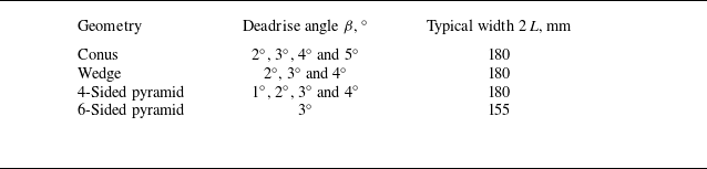
of all solids used in this study. The typical width of the solid
 $2L$
is 180 mm for the wedge, conus and 4-sided pyramid and 155 mm for the 6-sided pyramid. The deadrise angle is the angle between the horizontal plane and the bottom face of the solid, which varies between
 $1^\circ$
and
 $5^\circ$
depending on the solid, as shown in figure 1(c). To avoid ambiguity, the central edge of the wedge, side edges and edges of the pyramids are defined as shown in figure 1(b). The actual pre-impact air cushioning occurs at a local scale
 $L_0$
, which is of central interest in this study. Owing to the self-similar geometry of the problem, in the absence of a characteristic length scale (at
 $L_0 \lt \lt L$
),
 $L_0$
is a function of the relevant physical parameters of the problem and the deadrise angle
 $\beta$
, being a single geometrical parameter for each type of a body. The global length scale (half-width of the body)
 $L$
is only relevant for special cases with very low deadrise angles and low impact speeds.
Physical properties of the working liquids at 20
 $^{\circ }$
C.

Characteristics of the solids, deadrise angle
 $\beta$
and typical length
 $2L$
.

(a) Three-dimensional scheme of the experimental set-up. (b) Geometries of the different solids (wedge, conus, 4- and 6-sided pyramids) and definition of the central edge of the wedge, side edges and edges for the three-dimensional solids. (c) Central cut of the solid and definition of the deadrise angle
 $\beta$
. The typical width of the geometry
 $2L$
is 180 mm for the conus, wedge and 4-sided pyramid and 155 mm for the 6-sided pyramid. For illustrative purposes, the angles shown here are significantly larger than the actual ones.

Liquid contact with the solid and air entrapment are observed using a high-speed camera (Photron SA-Z), with a frame rate ranging from 1000 to 20 000 frames per second. All measurements and observations are made when the solid is in motion at a constant speed. To clearly see the contact on the surface of the solid, a total internal reflection set-up, described in Jain et al. (Reference Jain, Vega-Martínez and van der Meer2021c ), is used. The camera is positioned at an angle such that the interface acts like a mirror, and initially, it shows the image of a white plastic plate, see figure 1(a). As soon as there is contact between the solid and the liquid, the reflection coefficient changes (there is no more total internal reflection) and the contact becomes clearly visible, as shown in figure 3. Every experiments is at least repeated two times.
Due to the viewing angle of the camera, the image is distorted and needs to be calibrated. For each solid, the calibration is based on the actual size of the solid measured in the image. For a more detailed description of the experimental set-up and data processing, please refer to Carrat et al. (Reference Carrat, Gavrilov, Cherdantsev, Shmakova and Ermanyuk2023).
Free surface deformation and rim visualisation for the different solids: (a) conus, (b) 4 sided-and (c) 6 sided-pyramids, (d) wedge. The rim is highlighted for each solid with a red dashed line.

3. Free surface deformation
When a solid is very close to a free surface, before any contact, the free surface begins to deform. This deformation has been observed, measured and estimated for various types of solids, including spheres (Bouwhuis et al. Reference Bouwhuis, Hendrix, van der Meer and Snoeijer2015; Cherdantsev et al. Reference Cherdantsev, Gavrilov and Ermanyuk2021; Carrat et al. Reference Carrat, Shmakova, Cherdantsev, Gavrilov and Ermanyuk2021), disks (Jain Reference Jain2020; Jain et al. Reference Jain, Gauthier and van der Meer2021b , Reference Jain, Vega-Martínez and van der Meerc ), cones (Jain Reference Jain2020), wedges (Ross & Hicks Reference Ross and Hicks2019) and flat plates (Mayer & Krechetnikov Reference Mayer and Krechetnikov2018). The physical origin of this deformation is the same for all solids: the air between the object and the free surface is squeezed and pushed outward. The pressure in the thin layer of air at the pre-contact stage is higher near the vertex of the solid and decreases with the distance. Just before contact, a rim forms, as illustrated in figure 2.
The shape of the rim depends on the solid shape. For a cone, the rim has a circular shape (figure 2 a). For a 4-sided pyramid, the rim is a square slightly rounded at the corners (figure 2 b). For a 6-sided pyramid, the rim is a hexagon (figure 2 c). The rim of a wedge consists of two lines that are nearly parallel and slightly curved due to the finite length of the wedge (figure 2 d). This rim grows higher and higher with time, as observed by Jain (Reference Jain2020) for a conus and calculated by Ross & Hicks (Reference Ross and Hicks2019) for a wedge. The first wetting contact between the solid and the liquid occurs somewhere on the rim, as can be seen in figures 3 (a), 3(e), 3(i) and 3(n) for all solids. The only exception is the wedge. The first contacts always occur at the ends of the central edge (as shown in figure 2(d)), where three-dimensional effects due to the finite length of the wedge are strongly evident.
4. Air trapping
In this section, we describe the different patterns of air film collapse observed with the different solids and two liquids, water and a 2.5 % butanol–water solution (BWS).
4.1. One/multiple bubbles, central lines of bubbles
Formation of one or multiple bubbles for the three-dimensional solids: (a–d) conus, (e–h) 6-sided and (i–l) 4-sided pyramids. Formation of a central line of bubbles for the (m–p) wedge. (a,e,i,m) Several contact points whose locations depend on the solid shape. (b, f,j,n) The contact points join and entrapped an air film. (c,g,k,o) The outer border of the wetted area propagates outward while the air film retracts inward. (d,h,l,p) The air film collapses into a one/multiple bubbles or central lines of bubbles at the vertex of the solid. Experimental conditions: water,
 $V \sim 6.2\;\mathrm{cm}\,\mathrm{s}^{-1}$
and
 $\beta = 3^{\circ }$
. Readers are also referred Supplementary Movie 1 for the 6-sided pyramid, Supplementary Movie 2 for the 4-sided pyramid and Supplementary Movie 3 for the wedge. For the conus the readers are referred to the Supplementary Movies of Carrat et al. (Reference Carrat, Gavrilov, Cherdantsev, Shmakova and Ermanyuk2023).

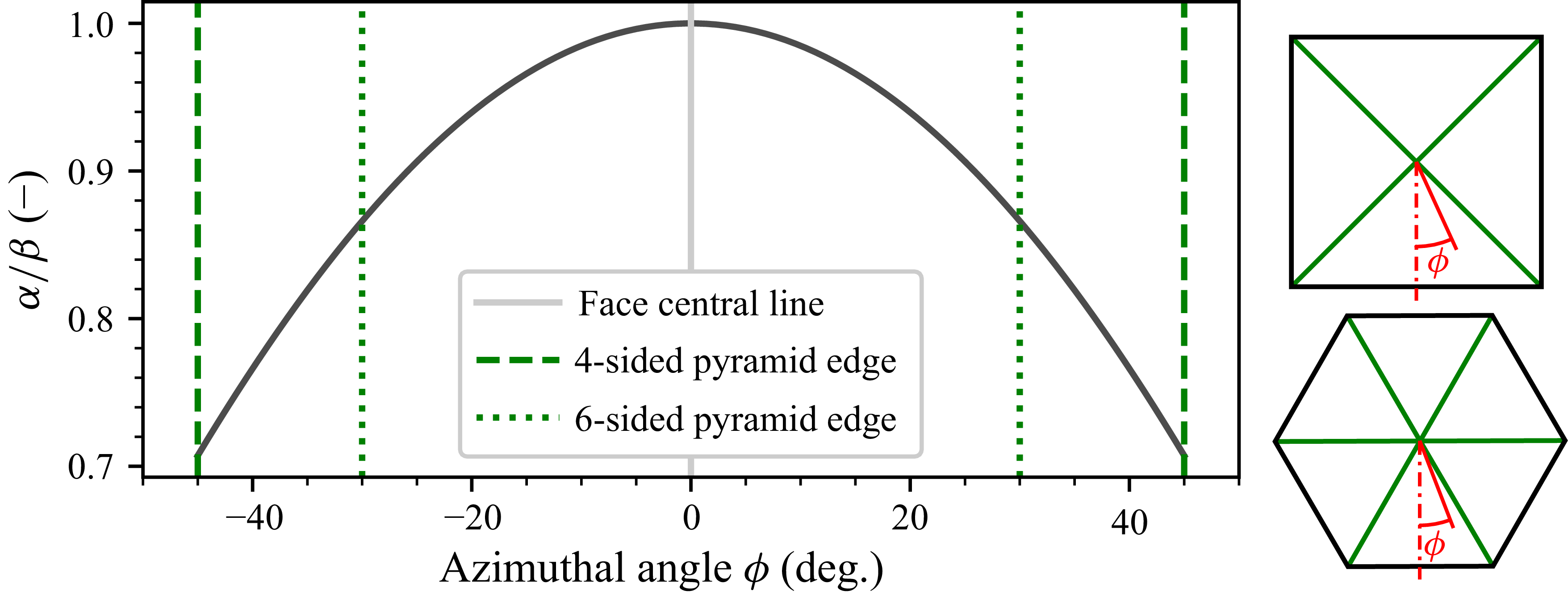
Variation of the ratio of the local
 $\alpha (\phi )$
and bottom face
 $\beta =\alpha (0)$
deadrise angles for the 4-sided and 6-sided pyramids with the azimuthal angle
 $\phi$
, defined on the right part of the figure.

Typically, in our experiments with three-dimensional solids (conus, 4- and 6-sided pyramids) the collapse of the air film due to contraction by capillary forces leads to one bubble or multiple small bubbles being located near the vertex of the solid. These two patterns emerge from similar types of initial air trapping, differing only at the final stage of the air film retraction, as shown in figure 3. Initial wetting contacts (initiated by very small imperfections of the solid surface and/or impurities on the liquid surface) spontaneously occur at the rim (see § 3), where the air film thickness is the smallest (see the small inset in figures 3(a), 3(e) and 3
(i)). These contact points are located on a circle for the conus (figure 3
a), a square for the 4-sided pyramid (figure 3
e) and a hexagon for the 6-sided pyramid (figure 3
i). Let us introduce the local deadrise angle for the pyramids
 $\alpha$
which varies with the azimuthal angle
 $\phi$
(figure 4). Geometric considerations, allowing us to estimate the local deadrise angle, are presented in Appendix A. Importantly, for the 4- and 6-faced pyramids, the initial wetting contacts take place along the central line of each face (
 $\phi =0$
), where the local deadrise angle
 $\alpha (\phi )$
reaches the highest value
 $\beta =\max [\alpha (\phi ) ]=\alpha (0)$
, as seen in figure 4. At first glance, this effect may appear counter-intuitive, since along the direction
 $\phi =0$
the distance from the rigid surface to the undisturbed free surface is the largest. However, precisely because the local deadrise angle along
 $\phi =0$
takes a maximum value, the pressure due to lubricating flow in the air film is the lowest. In § 6.2 it is shown that the horizontal distance between the points of initial wetting contact at opposite faces of a pyramid is proportional to
 $\beta ^{-2}$
. Assuming that the flow is approximately radial, the corresponding local quantity
 $\alpha (\phi )^{-2}$
is minimised at
 $\phi =0$
, where the initial wetting contact occurs.
The wetted areas grow in size with time and merge to trap an air volume in the centre of the solid, as shown in figures 3(b), 3( f) and 3(j). Interestingly, the final merging of the wetted areas occurs at the edges, shown in green in figure 1(b). This is a consequence of the local deadrise angle
 $\alpha$
variation with the azimuthal angle
 $\phi$
, which is minimum at the edges, as seen in figure 4. After the closure of the wetted zone, the trapped air retracts toward the vertex of the three-dimensional solid, while the outer border of the wetted zone propagates outwards, as shown in figures 6(c), 6(g) and 6(k). At the end of the retraction process the air volume can: (i) remain circular and form a single bubble (figure 3
d) or (ii) loose circular shape and break into multiple bubbles (figures 3(h) and 3(l)) close to the vertex of the pyramid. The latter scenario is more common for pyramids than cones for two reasons: (i) the shape of the rim is not circular for the pyramids, and (ii) a single bubble on the solid edge tends to be unstable and can easily split into two smaller bubbles on either side of the edge. For the 4-sided pyramid the shape of the outer border of the wetted area is similar to the analytical prediction of the contact line of Korobkin & Scolan (Reference Korobkin and Scolan2006), which is a square with rounded corners. However, we do not observe the slight concave deformation of the contact line near the centre of each face (around
 $\phi =0$
) (see figure 5 in Korobkin & Scolan (Reference Korobkin and Scolan2006)). In experiments we observe a convex outer border of the wetted area (see figures 3
k and 3
l).
Finally, let us discuss the air trapping in the case of the wedge as depicted in the lower row of images in figure 3. Here, we focus on the contact points that occur on the rim of the free surface (see figure 3 m) along two lines that are nearly parallel and straight. This allows us to obtain reliable data on the horizontal distance between the parallel lines in the vicinity of the middle cross-section of the wedge, taken as an approximation for a two-dimensional configuration. The growth and merging of initial wetting contact zones results in a trapping of a nearly rectangular air film (figure 3 n). The air film then retracts toward the central edge of the wedge and eventually breaks up into a line of bubbles localised on the central edge, shown in blue in figure 1(b). The outer border of the wetted zone propagates outward and ultimately reaches the side edges of the wedge, shown in red in figure 1(b).
4.2. Trail of bubbles
Formation of a trail of bubbles at the surface of (a–e) a conus (BWS,
 $V = 2.03\;\mathrm{cm}\,\mathrm{s}^{-1}$
and
 $\beta = 3^{\circ }$
) and ( f–j) a 4-sided pyramid (water,
 $V = 2.75\;\mathrm{cm}\,\mathrm{s}^{-1}$
and
 $\beta = 3^{\circ }$
). Readers are also referred to Supplementary Movie 4 for the 4-sided pyramid. For the conus the readers are referred to the Supplementary Movies of Carrat et al. (Reference Carrat, Gavrilov, Cherdantsev, Shmakova and Ermanyuk2023).

Figure 5 shows the formation of a trail of bubbles at the surface of a conus or a 4-sided pyramid. This regime occurs at low impact speeds. The first contacts are spontaneous and occur at the rim, as shown in figures 5(a) and 5( f). Then the wetted areas grow while no new contacts are formed at the rim (figures 5 b and 5 g). The resulting wetted area lacks symmetry, and the shape of the trapped air film is irregular, as illustrated in figures 5(c) and 5(h). After that, the trapped air film retracts (figures 5 d and 5 i), breaks locally and forms random trails of bubbles on the solid surface (figures 5 e and 5 j), contrasting with the regular case shown in figure 3, which is described in § 4.1.
4.3. Large central bubble, doughnut bubble
For small deadrise angles
 $\beta$
(less or equal to
 $2^\circ$
) and low impact speeds, there exists a regime in which a big flat bubble or a ‘doughnut’ bubble located near the vertex of the solid forms at the end of the air film retraction process. Typical time-sequence images corresponding to this regime are shown in figures 6 and 7 for the 4-sided pyramid and the conus, respectively.
Formation of a large bubble in the centre of the solid for (a–e) the conus (water,
 $V = 2.06$
cm s−1 and
 $\beta =2^\circ$
) and ( f–j) the 4-sided pyramid (water,
 $V = 1.56$
cm s−1 and
 $\beta =2^\circ$
).

In this regime the first contact occurs at the side edges shown in red in figure 1(b). The occurence of this regime depends on the finite horizontal extent
 $L$
of the impactor. For the conus, multiple contact points occur simultaneously at the side edge (figure 6
a). The wetted zones then quickly merge to form a large circular air film (figure 6
b). This air film retracts into a large flat bubble localised at the vertex (figures 6
c, 6
d and 6
e)). In contrast, for the 4-sided pyramid, four contact zones occur, each one being localised in the middle of the corresponding side edge (figure 6
f). The wetted zones grow in size and reach the pyramid corners (figure 6
b), thereby trapping a nearly rectangular air film (figure 6
c). This rectangular air film retracts (figure 6
i) and finally looses its rectangular shape at the end of the retraction process and turns into a large flat bubble (figure 6
j). This type of air film is not observed for the 6-sided pyramid in our range of experimental conditions. This is likely because our experiments are conducted with only a 6-sided pyramid with a deadrise angle of
 $3^\circ$
. For the 4-sided pyramid, a large central bubble or doughnut bubble is observed for deadrise angles less than or equal to
 $2^\circ$
.
Formation of a doughnut bubble at the surface of (a–e) a conus (water,
 $V = 2.15\;\mathrm{cm}\,\mathrm{s}^{-1}$
and
 $\beta = 2^{\circ }$
) and ( f–j) a 4-sided pyramid (water,
 $V = 0.95\;\mathrm{cm}\,\mathrm{s}^{-1}$
and
 $\beta = 2^{\circ }$
). (a, f) The first contacts occur at the solid edge. (b,g) Very strong capillary waves propagate inward. (c,h) Geometrical focusing of the capillary waves in the centre and contact at the solid vertex. (d,i) Doughnut bubble stills disturbed by capillary waves. (e,j) Doughnut bubble is stable and at rest around the solid vertex. Readers are also referred to Supplementary Movie 5 for the conus and Supplementary Movie 6 for the 4-sided pyramid.

In the same range of speeds and deadrise angles a large central bubble can spontaneously form a doughnut shape, as illustrated in figure 7 for the conus and the 4-sided pyramid. This happens when there are strong capillary waves at the interface between the air film and the liquid, visible for example in figures 7(b), 7(c), 7(g) and 7(h). The capillary waves focus near the centre of the air film due to the approximate symmetry of the air film and the amplification of wave amplitudes toward the centre of the bubble may result in wetting contact at the vertex of the solid. As a result, the large central air bubble is pierced, producing a stable doughnut-shaped bubble around the vertex of the solid. The source of the capillary waves is the receding edge of the air film. The presence of capillary waves at low impact speeds has been identified for configurations prior to air film rupture (e.g. Mirjalili & Mani Reference Mirjalili and Mani2020) and wetting contact development (e.g. Ross & Hicks Reference Ross and Hicks2019). In our case the process of air film retraction seems to be complicated by an inherent stochastic dynamics of the moving three-phase contact line due to possible local pinning events at uncontrollable micro-impurities. In some model problems the stochastic properties of advancing contact lines due to pinning events are well studied (see e.g. Clotet, Ortín & Santucci Reference Clotet, Ortín and Santucci2014). In this study, this issue falls outside the scope of our problem: we focus on identifying the parameter subdomain where we can identify the scaling law that corresponds to the air–liquid lubrication–inertia balance, adapted to our self-similar body geometry case.
4.4. Necklace, lines of bubbles
Images of the formation of a necklace and lines of bubbles for different solids: (a–e) conus, BWS,
 $V = 1.38\;\mathrm{cm}\,\mathrm{s}^{-1}$
and
 $\beta = 3^{\circ }$
, ( f–j) 6-sided, water,
 $V = 1.83\;\mathrm{cm}\,\mathrm{s}^{-1}$
and
 $\beta = 3^{\circ }$
and (k–o) 4-sided pyramids, water,
 $V = 1.65\;\mathrm{cm}\,\mathrm{s}^{-1}$
and
 $\beta = 3^{\circ }$
, (p–t) wedge, water,
 $V =1.99\;\mathrm{cm}\,\mathrm{s}^{-1}$
and
 $\beta = 3^{\circ }$
. (a, f,k,o) One contact point on the solid centre; (b,g,l,q) second contact points whose locations depend on the solid shape; (c,h,m,r) trapping of an air film band whose shape depend on the solid shape; (d,i,n,s) retraction of the air film band; (e,j,o,l) breaking of the air film into bubbles whose positions depend on the solid shape. Readers are also referred to Supplementary Movie 7 for the 6-sided pyramid, Supplementary Movie 8 for the 4-sided pyramid and Supplementary Movie 9 for the wedge. For the conus the readers are referred to the Supplementary Movies of Carrat et al. (Reference Carrat, Gavrilov, Cherdantsev, Shmakova and Ermanyuk2023).

For the three-dimensional solids (coni and pyramids) at low impact speeds, the first contact occurs at the vertex of the solid (see figures 8(a), 8( f) and 8(k)). The second contact then occurs at some distance from the vertex (figures 8(b), 8(g) and 8(l)) and traps an air film: a circular, hexagonal and rectangular ring for the conus, 6-sided and 4-sided pyramids, respectively (see figures 8(c), 8(h) and 8(m)). The contact line in the centre continues to propagate outward, while the outer contact line propagates inward. Ultimately, the width of air film reduces to a critical value corresponding to the onset of instability (figures 8 d, 8 i and 8 n)), the film breaks, and forms a necklace of bubbles (figures 8 e, 8 j and 8 o). The azimuthal perturbation at the border of the ring-shaped air film, which is clearly seen for the conus in figure 8(d), is qualitatively similar to a Rayleigh–Plateau instability.
For the two-dimensional solid (wedge) the first contacts always occur at the ends of the central edge. Then, similar to three-dimensional solids, there is a wetting contact at the wedge centre (see figure 8 p). Further, multiple wetting contacts occur along the central edge, as well as at some distance from the central edge where the local air film thickness is the smallest (see figure 8 q). As a result of this process, two parallel air films are formed on the surface of the solid on each side of the central edge (figure 8 r). This scenario is qualitatively consistent with numerical simulations (Ross & Hicks Reference Ross and Hicks2019) for a wedge impact. The air films retract (figure 8 s), and finally break, producing two nearly parallel lines of bubbles (figure 8 t).
4.5. Flow regime map of air film retraction
Figures 9 and 10 show the maps of the resulting bubble patterns observed for different solids and liquids within the studied range of impact speeds and deadrise angles. For the three-dimensional solids, six different types of bubble patterns are observed: doughnut-shaped bubble, large central bubble, necklace of bubbles, trail of bubbles and one/multiple bubbles located at the vertex (see figure 9). For the two-dimensional solid (wedge), three types of bubble patterns are observed: large central bubble, two lines of bubbles, line of bubbles at the central edge (see figure 10). For each combination of impact speed and deadrise angle we perform at least two experiments. Points with very close values of the impact speed are shown with a small artificial offsets in the deadrise angle in figures 9 and 10. The total number of experiments performed with two liquids, different body geometries, speeds and deadrise angles exceeds 1100. One can clearly identify the parameter ranges corresponding to different bubble patterns. The observed phenomena are reproducible. There is some uncertainty in the identification of the type of terminal bubble pattern only at low impact speeds. More details concerning the repeatability of the experiments are given in Appendix B.
Regime maps of bubble patterns resulting from air film collapse as function of speed and deadrise angle for the three-dimensional solids, (a) 4-sided pyramid for water, (b) 6-sided pyramid for water (c) and (d) conus for water and BWS, respectively. For visibility, points with very close impact speeds are shown with a small artificial offset on the deadrise angle.

Based on figure 9 it is possible to distinguish between the domains corresponding to different types of air film collapse, depending on the impact speed and the deadrise angle. It is clear that, above a certain speed (referred to as the transitional speed in this paper) there is a wide range of parameters where the air film retraction results in one/multiple bubbles near the vertex of the conus and pyramid (central edge for the wedge), as described in § 4.1. Below the transitional speed for the conus (see figures 9
c and 9
d) the retraction of the air film produces a trail of bubbles on the surface of the solid (see § 4.2) for a significant range of impact speeds. Finally, at low impact speed, one observes a large central bubble or a doughnut-shaped bubble (see § 4.3) for low deadrise angles (
 $\beta \leq 2^\circ$
) and a necklace of bubbles (see § 4.4) for high deadrise angles (
 $\beta \geq 2^\circ$
).
For the 4-sided and 6-sided pyramids (see figures 9
a and 9
b) below the transitional speed the margins between different regimes are less well defined than for the conus. Because of uncontrollable perturbations, different types of bubble patterns may be observed within the same range of impact speeds and deadrise angles: for low deadrise angles (
 $\beta \leq 2^\circ$
), a large central bubble and doughnut-shaped bubble, for higher deadrise angles (
 $\beta \geq 3^\circ$
), a trail and necklace of bubbles. It is worth noting that changing the deadrise angle from
 $2^\circ$
to
 $3^\circ$
for the 4-sided pyramid significantly reduces the amount of air trapped under the solid at low impact speed. Instead of having a large central bubble for a deadrise angle of
 $\beta =2^\circ$
, there is a necklace of bubbles for a deadrise angle of
 $\beta =3^\circ$
.
Impact speed and deadrise angle maps for (a) water and (b) BWS of the final air film type for the two-dimensional solid: the wedge. For visibility, points with very close impact speed are shown with a small artificial offset on the deadrise angle.

Qualitatively, the above observations are valid for the two-dimensional solid (wedge), see figure 10. Above a certain impact speed (transitional speed), air film trapping and retraction leads to the formation of a central line of bubbles, as described in § 4.1. Below the transitional speed, one observes two lines of bubbles, and a large central bubble.
Importantly, at very low impact speeds for all solids and liquids, there is a limit speed below which the first contact occurs at the solid vertex, the contact line propagates outward and there is no air trapping. This limit speed increases with the deadrise angle, in agreement with early study by Chuang & Milne (Reference Chuang and Milne1971), where no air film is observed for sufficiently large deadrise angles for a conus or a wedge.
Looking at the maps for the conus (see figures 9 c and 9 d) and the wedge (see figures 10 a and 10 b) for both liquids, one may conclude that the variation in surface tension only slightly shifts the boundaries of the domains corresponding to different air film retraction regimes. Therefore, despite the fact that the surface tension of BWS is significantly lower than that of water (see table 1), the quantitative effect of this variation is detectable but rather weak.
Transitional speed above which the terminal form of the air film retraction is represented by one/multiple bubbles for the three-dimensional solids (conus in purple and light purple, 4 and 6-sided pyramid respectively in blue and green) or a central line of bubbles for the two-dimensional solid (wedge in red and pink) as a function of the deadrise angle. The lines are continuous for water and discontinuous for the BWS. The markers cut in half are for the BWS.

Figure 11 combines all the transitional speeds from the regime maps (figures 9 and 10) into one graph for all solids and liquids. This transitional speed is increasing for deadrise angles bigger than
 $2^\circ$
for the 4-sided pyramid figure (in blue in figure 11), the conus (in purple and light purple in figure 11) and wedge (in red and pink in figure 11) for water and BWS. For a fixed deadrise angle, the transitional speed is not significantly affected by the geometry of the solid or the liquid and is approximately the same. For a deadrise angle of
 $1^\circ$
for the 4-sided pyramid in figure 9(a) this transitional speed is much higher (around 7 cm s−1). Indeed, the case of a solid with a very small deadrise angle is special, since it is close to the limiting case of a flat plate, where the wetting contacts always occur at the outer edges, as described in Mayer & Krechetnikov (Reference Mayer and Krechetnikov2018) and Bagg et al. (Reference Bagg, Pitto and Allen2022).
4.6. Summary
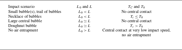
Let us summarise the impact scenarios and their underlying physics. The type of air film trapping and retraction in the present experiments depends on two key parameters: (i) the relation between the initial half-size
 $L_0$
of the air film (defined by an appropriate physical scaling as shown in figure 12 and § 5), and the half-size
 $L$
of the impacting body; (ii) the occurrence and time delay between the initial wetting contacts at the centre, at the liquid rim and at the outer edges of the solids. This idea is schematically described in table 3.
Impact scenario with
 $L_0$
the air film initial half-size,
 $L$
the half-size of the impacting body,
 $T_0$
the time of the first air film contact and the time of contact at the solid vertex
 $T_C$
.

The horizontal distance between the lowest point of the body (vertex for the three-dimensional solids and central edge for the two-dimensional solid) and the points of initial wetting events,
 $L_0$
, can be described by a scaling law relating the deadrise angle, the impact speed and physical properties of air and liquid, as explained in § 6.2. The horizontal extent of the solid is not significant. At low impact speeds,
 $L_0$
estimated from this scaling law may become comparable to or higher than
 $L$
. In addition, one may expect an increased role of capillary effects (Ross & Hicks Reference Ross and Hicks2019) and significant uncertainty in triggering of wetting events due to uncontrollable factors (e.g. small impurities on the surface of the solid or the free surface of the liquid). For a sphere, the spatial location of wetting contacts at low impact speed is affected by the critical value of the Weber number (as described by De Ruiter, Van Den Ende & Mugele (Reference De Ruiter, Van Den Ende and Mugele2015) and Cherdantsev et al. (Reference Cherdantsev, Gavrilov and Ermanyuk2021))
 \begin{equation} {\textit{We}}_{\textit{cr}} = \frac {\rho _l V^2 R}{\sigma } \simeq 1.8 .\end{equation}
Here,
 $R$
is the radius of the sphere,
 $\rho _l$
is the density of the liquid and
 $\sigma$
is the surface tension. Roughly speaking, for
 ${\textit{We}} \gt {\textit{We}}_{\textit{cr}}$
, the first contact occurs in the vicinity of the lowest point of the solid. However, when
 ${\textit{We}} \lt {\textit{We}}_{\textit{cr}}$
,
 $L_0$
increases significantly. In the case of a spherical lens with finite horizontal extent, as considered by Cherdantsev et al. (Reference Cherdantsev, Gavrilov and Ermanyuk2021), the wetting contact occurred near the edge of the lens in this situation. A similar effect can be expected for finite-sized wedges, coni and pyramids in the current experiments.
The wetting contact precisely at the lowest point of a body is rarely considered for an impacting sphere, except for the classical case of an impact on an ideal liquid in the absence of air (Schmieden Reference Schmieden1953). In the presence of air, the lubricating effect of a thin film of air on a smooth surface makes a contact less likely to happen. However, for bodies with sharp edges, such as those used in these experiments, a contact is still possible. The occurrence of a contact at precisely the lowest point of the body and/or at some distance
 $L_0$
(or
 $L$
) from the lowest point of the body depends on the interplay of the governing parameters (impact speeds and deadrise angles, and to a lesser extent , surface tension.). In table 3, the time instants for central and wetting contacts at the liquid rim are denoted by
 $T_C$
and
 $T_0$
, respectively. Within this classification, the most common case of the terminal bubble pattern resulting from the air film retraction is represented by one or several small bubbles located at the vertex of the solid, figure 3. For this simple case, there is neither a central contact, nor an outer edge contact. For this reason this case has been selected for further quantitative analysis to allow us to generalise the scaling law proposed in Carrat et al. (Reference Carrat, Gavrilov, Cherdantsev, Shmakova and Ermanyuk2023). The case with a trail of bubbles corresponds to a similar situation, figure 5, but it is affected by an azimuthal asymmetry in the retraction process during the early stage of retraction. The ‘necklace’ of bubbles is accompanied by a central contact that occurs earlier or simultaneously with the wetting contact on the outer edge of the air film, figure 8. Cases with a large central bubble and a doughnut-shaped bubble (figure 7) are characterised by the initial wetting contact at the outer edge, followed by central contact due to capillary wave focusing. Impact without air entrapment is observed at very low speed when the central contact occurs first and the gravity and capillary effects become more significant.
Estimation of the air film initial half-size based on the evolution of the half-sizes of the outer border of the wetted area (red squares) and the air film (blue circles) for different solids; (a) a conus,
 $V=6.24$
cm s−1,
 $\beta =3^\circ$
with water, (b) a 4-sided pyramid,
 $V=6.20$
cm s−1,
 $\beta =3^\circ$
with water, (c) a 6-sided pyramid,
 $V=6.35$
cm s−1,
 $\beta =3^\circ$
with water, (d) a wedge,
 $V=6.13$
cm s−1 and
 $\beta =3^\circ$
with water, The dashed and doted lines are respectively for the linear fitting of the liquid outer ring radius (in red) and the exponential fitting of the air film radius (in blue). In the image insets the darker parts are the part where the liquid is in contact with the solid.

5. Data processing
This section explains how the typical half-sizes of outer and inner borders of the wetted area are measured for all experiments with the terminal bubble pattern in the form of one/multiple bubbles for the conus and the pyramids, and a central line of bubbles for the wedge (domains marked by blue dots and light blue crosses in figures 9 and 10).
For the conus the half-sizes of the inner and outer borders of the wetted domain are the equivalent radii of the area occupied by the air film and the area delimited by the outer contact line, for more details see Carrat et al. (Reference Carrat, Gavrilov, Cherdantsev, Shmakova and Ermanyuk2023). A different approach is used for the pyramids and wedge, as they are not axisymmetric. The first step of the processing is to find the
 $x$
and
 $y$
positions of the solid vertex and their evolution over time. Then we look at the evolution of the grey-level profile along the line
 $y=y_{cent}(t)$
for the 4-sided pyramid and the wedge (dashed black line in the insets of figures 12
b and 12
d), along the line
 $x = x_{cent}(t)$
for the 6-sided pyramid (dashed black line in the inset of figure 12
c). The inner and outer borders of the wetted area are detected based on the gradient of the grey-level profile. The insets in figures 12(b), 12(c) and 12(d) show the measured size, the blue double-headed arrow for the inner border and the red double-headed arrow for the outer border for one frame. These measurements are taken for each frame as soon as contact is made.
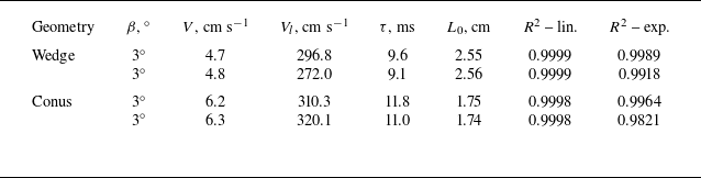
Figure 12 shows an example of the evolution of the half-sizes of the air film and the liquid outer border of the wetted area for all solids over time. As observed previously for the conus Carrat et al. (Reference Carrat, Gavrilov, Cherdantsev, Shmakova and Ermanyuk2023) and expected for the wedge, the half-size of the liquid outer border follows a linear law (red dashed line in figure 12). Breton, Tassin & Jacques (Reference Breton, Tassin and Jacques2020) observe a similar trend for a conus water entry. The slope of the linear fit represents the velocity of the wetted area outer border
 $V_l$
, which is discussed in § 6.1.
As soon as the thin air film is trapped and no more air can get out from below the solid, surface tension effects dominate the behaviour of the thin film and cause it to retract inward. Oguz & Prosperetti (Reference Oguz and Prosperetti1989) showed numerically that the retraction speed of the thin air film depends on its thickness. As explained by Thoroddsen et al. (Reference Thoroddsen, Etoh, Takehara, Ootsuka and Hatsuki2005) for a drop impacting a solid, the volume of air in the thin film is constant, and the size of the film is linked to its thickness. They proposed the following expression for the air film half-size :
 \begin{equation} L(t)= L_0 \boldsymbol{\cdot }\exp(-t/\tau ), \end{equation}
where
 $\tau$
represents the retraction time of the thin air film, which depends of surface tension, and
 $L_0$
the initial half-size. For example the retraction times are 11.8, 9.9, 9.7 and 6.2 ms respectively for the conus, 6-sided pyramid, 4-sided pyramid and wedge cases shown in figure 12. This exponential fitting (dotted blue line in figure 12) is in very good agreement with the experimental measurements of this present work for all solids, although it is applied to a solid impact on a liquid instead of a droplet impacting a solid. This expression is robust and seems to work for various types of impacts, such as solid sphere and conus impacts onto a liquid (Marston, Vakarelski & Thoroddsen Reference Marston, Vakarelski and Thoroddsen2011; Carrat et al. Reference Carrat, Gavrilov, Cherdantsev, Shmakova and Ermanyuk2023) and drop impacts onto a liquid (Lee et al. Reference Lee, Weon, Park, Kim, Pyo, Fezzaa and Je2020).
To obtain a more representative value, the initial half-size of the air film
 $L_0$
is estimated as the intersection of the two fittings, as shown in figure 12. The dependence of the initial half-size
 $L_0$
on the deadrise angle and impact speed is studied in detail in § 6.2. For all points, both liquids and one bubble/multiple bubbles patterns, the evolution of the characteristic half-sizes of the inner and outer borders of the wetted area follow with reasonable accuracy exponential and linear laws, respectively. The coefficient of determination calculated over all points is at least 0.95 for the exponential and 0.98 for the linear fitting in any experiments studied in this paper. Furthermore, for cases under the same impact conditions (solid, deadrise angle and impact speed) the results of the fittings are very similar and repeatable, as explained in Appendix B.
6. Results
6.1. Velocity of the liquid contact line at outer border of the wetted area
In this section we discuss the influence of the deadrise angle
 $\beta$
, impact speed
 $V$
and liquid properties on the propagation speed of the outer border of the wetted area estimated from the linear fitting, as shown in figure 12. The classical approach proposed in Wagner (Reference Wagner1932), with subsequent contribution by Schmieden (Reference Schmieden1953), yields the following estimates for the velocity of the contact line:
 \begin{equation} V_{w} = {\left \{\begin{array}{lc} \dfrac {\pi }{2} \dfrac {V}{\tan \beta } & \textrm {for the wedge,}\\[10pt] \dfrac {4}{\pi } \dfrac {V}{\tan \beta } & \textrm {for the conus.}\\ \end{array}\right .} \end{equation}
Hereinafter,
 $V_{w}$
is referred to as the Wagner velocity. Our previous work (Carrat et al. Reference Carrat, Gavrilov, Cherdantsev, Shmakova and Ermanyuk2023) showed that the experimental data for a conus are in fair agreement with the theory. It can be anticipated that for
 $n$
-sided pyramids the Wagner velocity is somewhat lower than the estimate for a wedge, and tends to the case of a conus as
 $n$
increases.
Velocities of the wetted area outer border
 $V_l$
obtained by linear fitting (see figure 12) as a function of the impact speed
 $V$
for different solids, deadrise angles for water and BWS. The colours correspond to the different solids and liquids: blue (water) and light blue (BWS) for the conus, purple (water) for the 6-sided pyramid, green (water) for the 4-sided pyramid, red (water) and pink (BWS) for the wedge. Each symbol corresponds to a deadrise angle: cross, square, round, triangle and diamond points are respectively for deadrise angles of
 $\beta =1^\circ$
,
 $2^\circ$
,
 $3^\circ$
,
 $4^\circ$
and
 $5^\circ$
. The markers cut in half are for the BWS.

Figure 13 shows the evolution of the contact line velocity in the outward direction
 $V_l$
with the impact speed
 $V$
for different solids and deadrise angles
 $\beta$
for water. Similar data are obtained for the BWS, as shown in figure 13 for the wedges and the coni. For a fixed geometry of the solid and a fixed deadrise angle,
 $V_l$
increases with the impact speed. For the same impact speed and the same solid,
 $V_l$
decreases as the deadrise angle increases. The data agree qualitatively with the expressions (6.1). The value of
 $V_l$
is generally higher for wedges than for pyramids and coni at a fixed deadrise angle
 $\beta$
. The data for the
 $6$
-sided pyramid and conus are in good agreement.
Variation of the ratio
 $({V_l}/{V}) \tan \beta$
with the impact speed
 $V$
for different solids, deadrise angles
 $\beta$
and liquids (water and BWS). The colours correspond to the different solids and liquids: blue (water) and light blue (BWS) for the conus, purple (water) for the 6-sided pyramid, green (water) for the 4-sided pyramid, red (water) and pink (BWS) for the wedge. The symbols correspond to the deadrise angles: cross, square, round, triangle and diamond points are respectively for deadrise angles of
 $\beta =1^\circ , 2^\circ , 3^\circ , 4^\circ \text{ and } 5^\circ$
. The markers cut in half are for the BWS. The red and blue dashed lines correspond to the ratios of
 $V_l/V \tan \beta$
equal to
 $\pi /2$
and
 $4/\pi$
, respectively.

The difference between different cases can be seen in detail in figure 14, where we show the ratio
 $({V_l}/{V}) \tan \beta$
as a function of the impact velocity
 $V$
. There are two regions in the graph, separated by an impact speed of 4.5 cm.s
 $^{-1}$
, indicated by a black vertical dashed line in the figure 14. Below this speed the ratio
 $({V_lV}/{\tan}) \beta$
increases when the impact speed decreases. Above this speed, the ratio remains relatively constant and is not significantly affected by the impact speed. Thus, an impact speed of 4.5 cm s
 $^{-1}$
can be considered a low-speed limit for the applicability of the Wagner theory for the range of parameters covered in the experiments. Above an impact speed of 4.5 cm.s
 $^{-1}$
for all three-dimensional solids, the experimental values of
 $({V_l}/{V}) \tan \beta$
are in good agreement with the predicted Wagner value of
 $({4}/{\pi })$
for the conus (blue dashed line in figure 14), if
 $\beta \geq 2^\circ$
. A similar observation for a conus with a deadrise angle of
 $7^\circ$
is presented by Elhimer et al. (Reference Elhimer, El Malki Alaoui, Gabillet and Jacques2022) or for coni with deadrise angles of
 $5^\circ$
,
 $20^\circ$
and
 $30^\circ$
as observed by Jain et al. (Reference Jain, Novaković, Bogaert and Van Der Meer2022). Similarly, for the wedge the existing data agree well with the Wagner value of
 $\pi /2$
(red dashed line in figure 14) for
 $\beta \geq 3^\circ$
. It can be seen that for all bodies (wedges, coni and pyramids) the case of low deadrise angle
 $\beta$
is special. The measured value of
 $({V_l}/{V}) \tan \beta$
may drop below the Wagner value. This effect is observed for the wedge at
 $\beta =2^\circ$
(red and pink squares in figure 14). It is also very pronounced for the 4-sided pyramid at
 $\beta =1^\circ$
(green diagonal crosses in figure 14) where
 $({V_l}/{V}) \tan \beta$
drops down to
 $0.93$
.
6.2. Initial half-size of the wetting pattern
Let us consider the scaling law governing the onset of the wetting events for the regimes where the final stage of the air film collapse is represented by one/multiple bubbles at the vertex for the three-dimensional solids and the central line of bubbles for the two-dimensional solid (wedge). These regimes are observed in the domains marked by blue dots and light blue crosses in figures 9 and 10. The initial half-size
 $L_0$
of the wetting pattern at the onset of the air-film-trapping process (defined in figure 12) is plotted in figure 15 as a function of the impact speed for water and different solids.
Log–log plot of the initial half-size
 $L_0$
as a function of the impact speed
 $V$
for water and different solids (conus, pyramids and wedge). Here,
 $L_0$
is estimated from the intersection between the fittings of the air film and outer border of the wetted area half-sizes, see figure 12. The colour corresponds to the different solids: conus (blue), 6-sided pyramid (purple), 4-sided pyramids (green), wedge (red). Each symbol corresponds to a deadrise angle: cross, square, round, triangle and diamond points are respectively for deadrise angles of
 $\beta =1^\circ , 2^\circ , 3^\circ , 4^\circ \text{ and } 5^\circ$
. The black dashed line is a slope of
 $1/V$
.

For a fixed impact speed
 $V$
the initial half-size
 $L_0$
decreases with the deadrise angle
 $\beta$
for all solids. However, for a given geometry and fixed
 $\beta$
, the initial half-size follows a power-law relationship
 $L_0 \sim V^{-1}$
, with good accuracy. This relationship is also observed for smooth solids (Hicks et al. Reference Hicks, Ermanyuk, Gavrilov and Purvis2012; Cherdantsev et al. Reference Cherdantsev, Gavrilov and Ermanyuk2021; Bagg et al. Reference Bagg, Pitto and Allen2022) but the exponent differs:
 $L_0\sim V^{-1/3}$
for a sphere impact. For a fixed impact speed
 $V$
and a deadrise angle
 $\beta$
of
 $2^\circ$
,
 $3^\circ$
or
 $4^\circ$
the initial half-size is always the largest for the conus and the smallest for the wedge. This is in agreement with the numerical (Faltinsen & Zhao Reference Faltinsen and Zhao1998; Ross & Hicks Reference Ross and Hicks2019) and experimental (Jain Reference Jain2020) results, which observe that the free surface deforms more for a wedge than a conus with the same deadrise angle and impact speed at the same moment in time. As a consequence, the wetting contact occurs closer to the solid vertex for a wedge than a conus and the initial half-size
 $L_0$
is smaller for a wedge than for a conus. For the 4- and 6-sided pyramids, the value of
 $L_0$
is nearly the same (see the data for
 $\beta =3^\circ$
indicated by the round markers in figure 15). It always falls between the values for the conus and the wedge, as could be expected since the pyramid shapes are a transition from the wedge to the conus, the latter being a pyramid with an infinite number of sides.
Log–log plot of the initial half-size
 $L_0$
as a function of the impact speed
 $V$
for two liquids (water and BWS), different solids (conus and wedge) and different deadrise angles. Here,
 $L_0$
is estimated from the intersection of the fittings of the air film and the outer border of the wetted area half-sizes, see figure 12. Each colour corresponds to a solid and liquid: conus for water (blue) and BWS (light blue), wedge for water (red) and BWS (pink). Each symbol corresponds to a deadrise angle: square, round, triangle and diamond points are respectively for deadrise angles of
 $\beta =2^\circ , 3^\circ , 4^\circ \text{ and } 5^\circ$
. The black dashed line is a slope of
 $1/V$
. The markers cut in half are for the BWS.

The initial half-size
 $L_0$
is plotted in figure 16 as a function of the impact speed for the conus and wedge, and for both liquids used in the present experiments. The results obtained for pure water and the BWS are similar. Surface tension has a weak effect on the initial half-size
 $L_0$
.
Now, let us discuss how the initial half-size
 $L_0$
scales with the key parameters of the problem. The concept of air–liquid lubrication–inertia balance has been discussed in great details for spheres impacting liquids and droplets impacting solid and liquids (Korobkin et al. Reference Korobkin, Ellis and Smith2008; Mandre et al. Reference Mandre, Mani and Brenner2009; Hicks & Purvis Reference Hicks and Purvis2010,Reference Hicks and Purvis2013). This approach is also used for a conus impact onto a liquid Carrat et al. (Reference Carrat, Gavrilov, Cherdantsev, Shmakova and Ermanyuk2023). Below, we use physical considerations inspired by Mandre et al. (Reference Mandre, Mani and Brenner2009) and Josserand & Thoroddsen (Reference Josserand and Thoroddsen2016) and show that the scaling law proposed by Carrat et al. (Reference Carrat, Gavrilov, Cherdantsev, Shmakova and Ermanyuk2023) applies to pyramids and wedges. First, let us clarify the role of the Froude number in the present experiments. Neglecting the thickness of the air layer, a solid of very small deadrise angle
 $\beta$
accelerates the liquid like a plate of expanding size
 $L_*(t)$
moving downward at a constant speed
 $V$
 \begin{equation} L_*(t)=Vt/\tan (\beta ) .\end{equation}
Based on the literature (Patton et al. Reference Patton1965; Brennen Reference Brennen1982; Korotkin Reference Korotkin2009), the added mass
 $m_a$
of such solids (in a deep liquid) is
 \begin{equation} m_a(t) = K \rho _l L_*^3(t), \end{equation}
where
 $\rho _l$
is the liquid density and
 $K$
is a constant dependent on the body shape. Tian et al. (Reference Tian, Tao, Li and Yang2017) observes that circular, hexagonal and square plates of the same area have a similar added mass. The inertial force
 $F_i$
acting on the disk can be evaluated by time differentiating the liquid impulse
 $m_a V$
 \begin{equation} F_i(t) = V \frac{\partial m_a(t)}{\partial t} \thicksim \rho_l V^4 t^2/\tan^3(\beta). \end{equation}
The inertial pressure
 $p_i$
can be estimated by dividing the inertial force
 $F_i$
by the area, which is proportional to
 $L_*^2$
 \begin{equation} p_i \thicksim F_i/L_*^2 = \rho _l V^2/\tan (\beta ). \end{equation}
It is interesting to note that the inertial pressure
 $p_i$
does not depend on time, as the problem is self-similar. The scale of the hydrostatic pressure can be evaluated as
 $p_h = \rho _l g V t$
, where
 $g$
is the acceleration due to gravity. The Froude number, which compares the inertial and hydrostatic pressures, is given by
 \begin{equation} Fr_*(t) = p_i/p_h \thicksim V/(\tan (\beta ) g t). \end{equation}
Given the low value of the deadrise angle and time (
 $\thicksim$
10 ms) the time-dependent Froude number respects the condition
 $Fr_*(t) \geq 1$
, and inertia dominates over buoyancy in the liquid for this study.
Second, the thickness of the air layer is observed to be of the order of
 $\delta$
 $\sim 10$
μm, for various solid impacts (flat plate Mayer & Krechetnikov (Reference Mayer and Krechetnikov2018), cone or wedge Jain et al. (Reference Jain, Novaković, Bogaert and Van Der Meer2022) and even wave-structured disk Fan et al. (Reference Fan, Jain and van der Meer2024)) and the deadrise angle
 $\beta$
is very small. Therefore, the fluid motion can be described within the lubrication approximation as a squeeze flow of a Newtonian fluid with dynamic viscosity
 $\mu _{g}$
between two flat plates moving towards each other at a speed
 $V$
. Thus the radial variation of the pressure
 $p_g(r)$
in the gap between the two flat plates is expressed as described by Hamrock, Schmid & Jacobson (Reference Hamrock, Schmid and Jacobson2004)
 \begin{equation} \frac {\text{d}p_g}{\text{d}r}=\frac {6r\mu _g V}{\delta ^3} \text{ with } 0 \lt r \lt L_* \text{ the radial position}. \end{equation}
Since we are considering a self-similar geometry, the dependence on the geometric parameters is only a function of the deadrise angle. Therefore, we assume that the air gap thickness
 $\delta$
at some distance
 $L_*$
scales as
 $\delta / L_* = C \tan \beta$
, with
 $C$
a proportional coefficient. Finally, one obtains the scale for the pressure in the air film in the viscous lubrication regime
 $p_g$
 \begin{equation} p_g \sim \mu _{g}V/(L_* C^3 \tan ^3(\beta )). \end{equation}
The initial half-size of the air film
 $L_0$
is defined as the moment when the pressure in the liquid equals the lubrication pressure in the thin air layer. Using
 $p_i = p_g$
gives us a scaling relation for the initial half-size of the air film
 $L_0 \sim A/C^3$
for a solid with a deadrise angle
 $\beta$
impacting a liquid at a constant speed
 $V$
, where
 \begin{equation} A= \mu _g/(\rho _l V \tan ^2(\beta )). \end{equation}
Note that, if we assume
 $C=O(1)$
, it does not guarantee that the experimentally determined coefficient
 $a$
in
 $L_0=aA$
remains
 $O(1)$
since
 $a\sim 1/C^3$
. Below, in the calculation of
 $A$
we used
 $\mu _g=1.8.10^{-5}$
 $\mathrm{Pa\,s}$
as the reference dynamic viscosity of air at 20
 $^{\circ }$
C. Importantly, the definition of
 $A$
can be applied to all solids in our study, whether they are two- or three-dimensional. It is worth noting that the non-dimensional quantity
 $A/L_0=\mu _g/(\rho _l L_0 V \tan ^2(\beta ))$
is a version of the Stokes number. The latter is widely used in the discussion of scaling for air trapping by spherical droplets impacting solid and liquid substrates (see, e.g. Mandre et al. Reference Mandre, Mani and Brenner2009; Bouwhuis et al. Reference Bouwhuis, Hendrix, van der Meer and Snoeijer2015; Josserand & Thoroddsen Reference Josserand and Thoroddsen2016). In our case the geometry is self-similar and there is no typical length. The Stokes number formulated using
 $L_0$
as a length scale (which is not known prior to experiments) is equivalent to
 $a^{-1}$
.
Figure 17 shows the initial half-size of the air film
 $L_0$
as a function of the scaling parameter
 $A$
for different solids and deadrise angles.
Log–log plot of the initial air film half-size
 $L_0$
as a function of the scaling parameter
 $A\,=\,\mu _g/(\rho _l V \tan ^2(\beta ))$
based on the idea of air–liquid lubrication–inertia balance. Each colour corresponds to a solid and liquid: conus for water (blue) and BWS (light blue), 6-sided pyramid (purple), 4-sided pyramid (green), wedge for water (red) and BWS (pink). Each symbol corresponds to a deadrise angle: cross, square, round, triangle and diamond points are respectively for deadrise angles of
 $\beta =1^\circ , 2^\circ , 3^\circ , 4^\circ \text{ and } 5^\circ$
. The linear fitting of the data is added as a dashed line. The markers cut in half are for the BWS.

It can be clearly seen that the data obtained for all bodies follow essentially the same scaling law over a wide range of
 $A$
covering two decades. For each specific body shape, the data are essentially universal for
 $2^\circ \leq \beta \leq 4^\circ$
. The case of
 $\beta = 1^\circ$
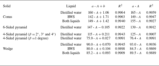
(where detailed data are available for the 4-sided pyramid) should be considered separately: it clearly follows the same scaling, but the numerical value of the prefactor differs significantly. For each type of solid, the experimental points obtained at all values of the deadrise angle are fitted by a linear function
 $a\boldsymbol{\cdot }A + b$
(see table 4). In figure 17, the fitting with an intercept of
 $b = 0$
is also shown as a dashed line for each solid. There are two sets of fits for the 4-sided pyramids: one for deadrise angles of
 $\beta = 2^\circ$
,
 $3^\circ$
and
 $4^\circ$
, and another for a deadrise angle of
 $1^\circ$
.
Fitting results of the initial half-size
 $L_0$
for the different solids as a function of the parameter
 $A\,=\,\mu _g/(\rho _l V \tan ^2(\beta ))$
for distilled water and BWS with
 $a$
the slope and
 $b$
the intercept. Here,
 $R^2$
is the determination coefficient of the fittings.

It is important to note that for all fittings the intercept value
 $b$
is very small and close to zero (see table 4), therefore for all solids
 $L_0 \sim A$
with good accuracy. The fitting results for the wedge and the conus show that surface tension has a weak, but detectable, effect on the prefactor
 $a$
, which is smaller for the BWS compared with distilled water. The prefactor
 $a$
for the two-dimensional solid (wedge) is the smallest (approximately 93 for water). It significantly increases for the three-dimensional solids, reaching (for water) values of
 $a=125$
,
 $139$
and
 $165$
for the 4-sided, 6-sided pyramids and conus, respectively. For the 4-sided pyramid with
 $\beta =1^\circ$
the value of
 $a$
is very low:
 $a=76$
for distilled water. Since the scaling law remains valid (the relevant data are shown by green diagonal crosses in figure 17), one may assume that the underlying physics remains the same and the drop of
 $a$
is due to the effect of the finite thickness of the lubrication layer. In an idealised case of a body impacting onto a liquid in the absence of air, the geometry of the body penetrating into the liquid is known. In the case of impact of the body onto a gas–liquid interface the geometry of the rigid body is modified by the lubricating gas layer. At low deadrise angle
 $\beta$
the relative effect of the finite thickness of the gas layer is expected to be stronger: it may be responsible for changing the value of prefactor
 $a$
due to a small change in the gas–liquid lubrication–inertia balance.
7. Conclusion
In this paper we investigate air entrapment during solid impact onto a liquid with small deadrise angles. The actual body shapes vary from purely two-dimensional (wedge) to purely axisymmetric (conus), with 4- and 6-sided pyramids as intermediate genuinely three-dimensional cases. The whole set of present shapes can be seen as an important complement, filling the gap between a flat plate and a sphere. The latter two cases are covered by an extensive literature (Josserand & Thoroddsen Reference Josserand and Thoroddsen2016; Jain Reference Jain2020). The distinctive feature of wedge, pyramid and conus is the self-similarity of the problem. Therefore, one may expect the existence of flow regimes where the transverse size of the body does not play a significant role in the scaling of the physical phenomena. Experimentally, a body with a sufficiently large horizontal extent can be considered virtually infinite within a suitable range of the governing parameters (deadrise angle, impact speed).
As a key visualisation technique we use total internal reflection (Jain et al. Reference Jain, Gauthier and van der Meer2021b ). For the conus and the pyramids, various air-trapping scenarios are observed and classified based on the air bubble patterns resulting from the trapped air film collapse. The observed bubble patterns include one or a few small bubbles at the body vertex, a random trail of bubbles, a regular ring (`necklace’) of bubbles, a large flat central bubble, a large doughnut-shaped flat central bubble and no air film. The scenarios of air film collapse are defined by two main factors: whether the wetting contact occurs at the facet or outer edge of the body, and whether there is contact at the vertex of the body. The scenarios for the wedge are mostly two-dimensional versions of those listed above.
Above a transitional speed, which depends on the deadrise angle (figure 11), only entrapment of small central air bubble(s) is observed, independent of the horizontal extent of the impacting body. Also, there is no wetting contact at the vertex during air film trapping and collapse. For this case, we investigate the initial size of the air film, which is understood as the horizontal distance between the lowest point of the body and the initial wetting contact, and the outward propagation of the contact line. The measured values of the outward velocity of the contact line for the wedge and the conus agree well with the Wagner theory predictions for two-dimensional and three-dimensional solids, respectively. Three-dimensional solids without axial symmetry, such as pyramids, exhibit intermediate velocity values of the contact line that are closer to those of the cone. Liquid surface tension has no significant effect on the contact line velocity, in agreement with the classic theory by Wagner (Reference Wagner1932), which also neglects the presence of air.
The initial half-size of the air film is measured for an air film retraction resulting in one/multiples bubbles near the vertex of the conus and pyramids, and a central line of bubbles for the wedge. The initial half-size of the air film is inversely proportional to the impact speed and the squared tangent of the deadrise angle. This relationship is derived from the balance between the inertial pressure in the liquid and the lubrication pressure in the thin air layer between the solid and the liquid. Qualitatively, this scaling is the same for all types of solids considered in this study. However, there is a systematic variation in the proportionality coefficient: the smallest value is found for wedges, and the largest value for cones, with intermediate values for pyramids. The cases with the smallest deadrise angles (
 $\beta \leq 2^\circ$
for two-dimensional solid and
 $\beta = 1^\circ$
for three-dimensional solids) tend to have lower values of the proportionality coefficient. The non-universal value of the proportionality coefficient reflects the effect of the finite thickness of the lubrication air layer, which becomes more pronounced at the lowest values of
 $\beta$
. The initial half-size of the air film weakly depends on the liquid surface tension. A twofold decrease in surface tension leads to a roughly
 $10\%$
decrease in the proportionality coefficient of the scaling law.
This study allows us to draw some general conclusions about the role of geometry in the air trapping. For a sphere the horizontal size of the air film scales with impact speed
 $V$
and radius
 $R$
as
 $V^{-1/3}R^{2/3}$
. For a wedge, conus and pyramid the relevant scaling with impact speed
 $V$
and deadrise angle
 $\beta$
is
 $V^{-1}(\tan \beta )^{-2}$
. Owing to the strong difference in exponents, one can use it to manipulate the air-trapping effect. For instance, a liquid droplet impacting a flat solid surface produces air trapping with a scaling similar to the case of a sphere. However, if the solid surface has a small-scale microstructure (micro-wedges, pyramids or coni), the air trapping can be significantly modified. Similarly, at the impact of a conus or pyramid on a liquid, the sharp or rounded shape of the body in the vicinity of the vertex allows us to switch from one scaling of air trapping to another if needed in some applications.
Supplementary movies
Supplementary movies are available at https://doi.org/10.1017/jfm.2026.11296.
Acknowledgements
The authors would like to thank A.S. Kizhevatov and A.V. Silaev for help with the experiments and the construction of the experimental set-up. The authors are grateful to the referees for their constructive comments. AI has only been used to improve the grammar using the English editor powered by YandexGPT 5.
Funding
The research was carried out under a State Budget contract with the Lavrentiev Institute of Hydrodynamics (project FWGG-2026-0005) and Kutateladze Institute of Thermophysics (project FWNS-2026-0006).
Author contributions
Conceptualisation, J.-B.C, A.C. and E.E; methodology, J.-B.C.; software, J.-B.C; validation, J.-B.C, N.G., A.C., N.S. and E.E.; formal analysis, J.-B.C, A.C. and E.E.; investigation, J.-B.C; resources, J.-B.C, N.G., A.C., N.S. and E.E.; data curation, J.-B.C and N.G.; writing – original draft preparation, J.-B.C.; writing – review and editing, J.-B.C, N.G., A.C., N.S. and E.E.; visualisation, J.-B.C. ; supervision, E.E. and A.C.; project administration, E.E.; funding acquisition, E.E. All authors have read and agreed to the published version of the manuscript.
Declaration of interests
The authors report no conflicts of interest.
Data availability statement
The data that support the findings of this study are available from the corresponding author upon reasonable request.
Appendix A. Estimation of the local deadrise angle
For the pyramids, the deadrise angle varies with the azimuthal angle
 $\phi$
. The azimuthal angle
 $\phi$
is defined as shown in figure 18. It can be shown that for any azimuthal angle
 $\phi$
 \begin{equation} \tan (\alpha (\phi ))=\frac {h}{l(\phi )}, \end{equation}
with
 $\alpha (\phi )$
the deadrise angle along the radial direction corresponding to the azimuthal angle
 $\phi$
, and
 $h$
the height of the pyramid. The height of the pyramid
 $h$
can be expressed for
 $\phi =0$
as
 \begin{equation} h=l(0) \tan (\alpha (0)=L\tan (\beta ) .\end{equation}
Using (A1) and (A2) it can be shown that, for one face of the solid,
 \begin{equation} \alpha (\phi )=\arctan [\tan (\beta )\cos (\phi )] .\end{equation}
This formula is used to estimate the local deadrise angle
 $\alpha (\phi )$
shown in figure 4 with
 $\phi \in [-\pi /4, \pi /4]$
for the 4-sided pyramid and
 $\phi \in [-\pi /6, \pi /6]$
for the 6-sided pyramid.
Geometrical considerations for the estimation of the local deadrise angle
 $\alpha (\phi )$
as a function of the azimuthal angle
 $\phi$
.

Appendix B. Repeatability between experiments
In order to have representative results in this study, each experiment (defined by a type of body geometry, an impact speed and deadrise angle) is repeated at least two times, as shown in figures 9 and 10. In total more than 1100 experiments have been conducted. However, it is important to distinguish between the type of terminal pattern of collapsed air film and the local shapes or positions of the bubbles at the surface of the solid in a particular experiment.
For the case where the terminal pattern of after collapse of air film is one/multiple bubbles (for the three-dimensional solids) or a central line of bubbles (for the two-dimensional solid) the local shapes or location of the bubbles are very similar under identical impact conditions. This is shown for example in (a) and (c) for the wedge and (b) and (d) for the conus in figure 19.
Central line of bubbles for a wedge with a deadrise angle of
 $\beta =3^\circ$
and an impact speed of (a)
 $V=4.71$
cm s−1 and (c)
 $V=4.75$
cm s−1. One bubble at the conus vertex with a deadrise angle of
 $\beta =3^\circ$
and an impact speed of (b)
 $V=6.24$
cm s−1 and (d)
 $V=6.26$
cm s−1.

For the trail of bubbles since the positions of the first contacts are azimuthally random and the closing is not symmetrical (as observed in figure 5), the local shapes or positions of the bubbles vary a lot between experiments in the same impact conditions. For the other types: necklace of bubbles, lines of bubbles, doughnut-shaped bubble, large central bubble, this a bit trickier, the local variation of the bubbles’ geometry, even though the impact conditions are similar, can be important. However, the type of the terminal bubble pattern is well reproducible.
For the necklace of bubbles in figure 20 we observe that the type of air bubble pattern is identical for the same velocity and deadrise angle for the conus (a and d), the 4-sided pyramid (b and e) and the 6-sided pyramid (c and f). The lines or ring along which the bubbles are located are well repeatable, and the total number of bubbles on each line is relatively stable. However, there are some minor variations in the positions and sizes of individual bubbles due to the sensitivity of this type of air film to the initial contact, which can occur spontaneously on the solid surface. For the wedge the same observation is made for the parallel lines of bubbles in figures 21(a) and 21(d). Although there are some local differences, the lines along which the bubbles are positioned are well reproducible.
Necklace of bubbles for different solids: (a)
 $V=1.38$
cm s−1 and (d)
 $V=1.43$
cm s−1 for the conus and a deadrise angle of
 $\beta =3^\circ$
, (b)
 $V=1.23$
cm s−1 and (e)
 $V=1.25$
cm s−1 for the 4-sided pyramid and a deadrise angle of
 $\beta =3^\circ$
, (c)
 $V=1.66$
cm s−1 and ( f)
 $V=1.67$
cm s−1 for the 6-sided pyramid and a deadrise angle of
 $\beta =3^\circ$
.

Parallel lines of bubbles for a wedge, a deadrise angle of
 $\beta =3^\circ$
and an impact speed of (a)
 $V=1.99$
cm s−1 and (d)
 $V=1.99$
cm s−1. Doughnut-shaped bubble for a conus, a deadrise angle of
 $\beta =1^\circ$
and an impact speed of (b)
 $V=1.02$
cm s−1 and (e)
 $V=1.02$
cm s−1. Large central bubble for a conus, a deadrise angle of
 $\beta =2^\circ$
and an impact speed of (b)
 $V=2.10$
cm s−1 and (e)
 $V=2.15$
cm s−1.

For a doughnut-shaped bubble even though the impact velocity and solid deadrise angle are similar, the final doughnut-shaped bubble is different as can be seen in figures 21(b) and 21(e). In the case of figure 21(e), the major diameter of the bubble is slightly smaller, but the minor diameter is larger compared with figure 21(b). Therefore, the volume of the bubble may be the same in both cases, but the shapes of the bubbles are different. This is because the contact at the 4-sided pyramid tip happens earlier for case (b) than case (e) in figure 21. Figures 21(c) and 21( f) show two cases of a large central bubble for the conus in similar conditions, again the large central bubble is well repeatable as such, but there are some local variations of the bubble shape between the two cases.
So, the cases of final air bubble pattern, of one/multiple bubbles for the three-dimensional solids and central line of bubbles for the two-dimensional solid, are highly reproducible, with minimum case-to-case variation. The corresponding regimes are studied in detail in § 6. The measured evolution of the inside and outer borders of the wetted area is very similar for experiments made under the same impact conditions. Figure 22 shows the evolution of the inside and outer borders for two experiments performed in similar conditions for the (a) wedge and (b) conus. It is observed that the results obtained from the fittings (shown in table 5) for both solids are similar with the same impact conditions.
Results of the fitting of the different experiments showed in figure 22. Here,
 $V$
is the impact speed,
 $\beta$
is the solid deadrise angle,
 $L_0$
the initial half-size,
 $V_l$
is the velocity of the outer border of the wetted area,
 $\tau$
is the retraction time of the air film and
 $R^2$
represents the determination coefficients for the linear fitting of the outer border of the wetted area and the exponential fitting of the air film half-size.

Evolution of the inside and outer borders for two experiments in similar conditions for the (a) wedge with a deadrise angle of
 $\beta =3^\circ$
for an impact speed of
 $V=4.7$
cm s−1 in red and
 $V=4.7$
cm s−1 in blue and (b) conus with a deadrise angle of
 $\beta =3^\circ$
for an impact speed of
 $V=6.2$
cm s−1 in red and
 $V=6.3$
cm s−1 in blue. Dotted and dashed lines represent the fittings of the inner and outer borders, respectively.

In conclusion, the terminal air bubble pattern is well repeatable for experiments performed under the same conditions, even though locally there can be some minor differences. The measurements of the time evolution of the inner and outer borders of the wetted area provide robust and reliable data characterising the air film behaviour and its initial size for the regime of air–liquid lubrication–inertia balance, which corresponds to the terminal air bubble pattern in the form of one/multiple bubbles at the body vertex.