1 Introduction
Two-phase displacement flows in narrow gaps are ubiquitous in industrial, geophysical and biological processes. Examples include coating processes (Coyle, Macosko & Scriven Reference Coyle, Macosko and Scriven1986), enhanced oil recovery (Sheng Reference Sheng2010),
 $\text{CO}_{2}$
sequestration (Huppert & Neufeld Reference Huppert and Neufeld2014), soil drying (Bachmann & van der Ploeg Reference Bachmann and van der Ploeg2002) and lung biomechanics (Heil & Hazel Reference Heil and Hazel2011). In the canonical problem, a fluid is driven into a gap initially completely filled by another fluid. When the driving fluid is the less viscous of the two, destabilising viscous forces can overcome stabilising surface tension forces, and the interface between the two fluids develops a finger-like morphology (Saffman & Taylor Reference Saffman and Taylor1958) that depends principally on the gap geometry and the driving flow rate. Such viscous fingering has been widely studied in rigid Hele-Shaw cells as an archetype for pattern-forming interfacial instabilities observed in many systems (Arneodo et al.
Reference Arneodo, Couder, Grasseau, Hakim and Rabaud1989; Ben-Jacob & Garik Reference Ben-Jacob and Garik1990; Ben-Jacob et al.
Reference Ben-Jacob, Shmueli, Shochet and Tenenbaum1992).
In a compliant radial Hele-Shaw cell, the onset of the fingering instability is delayed: it occurs at a higher flow rate than in equivalent rigid-walled cells (Pihler-Puzović et al. Reference Pihler-Puzović, Illien, Heil and Juel2012). The interface is observed to destabilise into a ring of short constant-length fingers (Pihler-Puzović et al. Reference Pihler-Puzović, Illien, Heil and Juel2012) that contrasts with the branched pattern formed in rigid cells. The nature of this instability and its connection to other interfacial instabilities remain incompletely understood. This is partly because, in the radial geometry, under constant-flux driving, the radial velocity of the propagating interface decreases with time, so that the pattern continuously evolves and the interface eventually restabilises. Moreover, the axisymmetric base state also evolves in time, meaning that a linear instability analysis is only valid assuming a suitable separation of time scales (Pihler-Puzović et al. Reference Pihler-Puzović, Périllat, Russell, Juel and Heil2013, Reference Pihler-Puzović, Juel, Peng, Lister and Heil2015; Peng et al. Reference Peng, Pihler-Puzović, Juel, Heil and Lister2015). The fluid injection leads to inflation of the compliant surface, so that the advancing interface propagates into a radially converging gap between the rigid bottom boundary and the compliant top wall, a geometry that also occurs during the steady peeling of a strip of viscous adhesive (McEwan & Taylor Reference McEwan and Taylor1966) or when a liquid meniscus is formed in the gap between two rotating cylinders (Rabaud, Michalland & Couder Reference Rabaud, Michalland and Couder1990; Couder Reference Couder, Batchelor, Moffatt and Worster2000). In both of these examples, interfacial instability also leads to the formation of finite-length fingers, known as the printer’s instability in the rotating-cylinder scenario.
In this paper, we study the constant-length fingering instability by developing an axial compliant Hele-Shaw set-up that avoids the unsteady interface evolution inherent in the radial system. Our principal aim is to quantify the saturated finite-length fingers that develop for sufficiently high capillary numbers,
 $Ca=\unicode[STIX]{x1D707}U/\unicode[STIX]{x1D70E}$
, where
 $U$
is the speed of the interface,
 $\unicode[STIX]{x1D707}$
is the dynamic viscosity of the more viscous fluid and
 $\unicode[STIX]{x1D70E}$
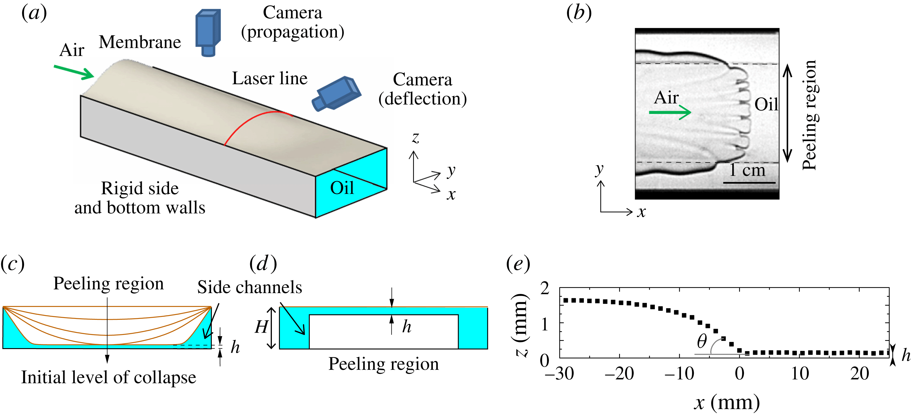
is the surface tension at the interface. We consider a rectangular channel with a flexible upper boundary (membrane); see figure 1(a). A potential difficulty with this geometry is that, although the propagation is steady, the presence of the sidewall boundaries means that, unlike the radial case, a front of uniform curvature is never observed and an analogue of the classic Saffman–Taylor finger develops instead (Ducloué et al.
Reference Ducloué, Hazel, Thompson and Juel2017). However, we have found that changes to the geometry of the cross-section of the compliant channel can generate fingers with effectively flat tips, when viewed from above, over a significant proportion of the channel width (figure 1
b).
(a) Experimental set-up, which consists of a rigid Hele-Shaw channel topped with an elastic membrane. Nitrogen is injected at a constant flow rate from one end of the oil-filled channel. The channel cross-section shown in (d) was used in the experiments in order to generate a flat peeling front. (b) Typical picture of the interface viewed from above: the approximately planar front propagating over the central block is deformed by small-scale finite-length fingers. Dashed lines highlight the edges of the block. (c) Schematic diagram of unoccluded channel cross-sections obtained when a negative transmural pressure is imposed prior to experimentation. (d) Cross-section for the present experiments, partially occluded by an axially uniform rectangular block. The cross-section of the partially occluded channel mimics the most strongly collapsed cross-section shown in (c) by including a uniform shallow central layer, which is isolated from side boundaries by deep side channels. (e) Axial profile along the centreline of the channel (
 $y=0$
) showing the deflection of the top membrane during the steady propagation of an air finger into the oil. The air–oil interface sits at
 $x=0$
, and
 $z=0$
has been taken on the surface of the block. The macroscopic peeling angle
 $\unicode[STIX]{x1D703}$
is indicated.

In our compliant channel, the morphology of the steadily advancing finger, which we refer to as the base state, is selected by the interaction between the wall deformation and the internal fluid flow (Heil & Hazel Reference Heil and Hazel2011; Ducloué et al.
Reference Ducloué, Hazel, Thompson and Juel2017). Ducloué et al. (Reference Ducloué, Hazel, Thompson and Juel2017) systematically investigated the dependence of this base state on the transmural pressure, which changes the level of collapse of the channel prior to injection of the finger; see figure 1(c). For modest levels of collapse, the advancing interface is only slightly modified from that found in rigid channels. At higher levels of collapse, when the compliant wall is in near contact with the rigid wall over a considerable proportion of the channel, and for sufficiently high
 $Ca$
, the advancing interface forms an approximately flat front in the near-contact region, which we term the peeling region by analogy with McEwan & Taylor (Reference McEwan and Taylor1966). Thus, in this geometry, the interface locally exhibits the desired properties of uniform curvature and a steady propagation speed under a compliant surface.
The existence of the flat-tipped peeling finger arises through a competition between viscous and elastic forces: it is selected at higher
 $Ca$
, when it becomes more favourable to lift the membrane than displace fluid in the two deeper side channels (Ducloué et al.
Reference Ducloué, Hazel, Thompson and Juel2017). As a result, the critical capillary number for the existence of this peeling mode gives a lower bound on the range of
 $Ca$
that we can explore to study finite-length fingering. This lower bound increases with the cost of elastic deformation, and thus with the membrane thickness, so that as the rigid limit is approached, the flat-tipped finger no longer exists for any
 $Ca$
.
In this paper, rather than collapsing the membrane onto the bottom of the channel to induce transverse depth variations, the cross-section of the channel was modified by bonding a tall axially uniform rectangular rigid block to the bottom boundary (see figure 1
d). The cross-section of this partially occluded channel topped with the horizontal membrane mimics that of the collapsed channel, keeping the essential feature of a shallow central layer isolated from the side boundaries by two deeper channels. This configuration gives us the ability to control the extent of the uniform peeling region by selecting the width of the block, and to impose larger controlled film thicknesses in the central peeling region, which can be varied through the slight collapse of the membrane. The deeper side channels are essential if the flat front peeling region is to be realised. If the side channels are not present, then the geometry is simply that of a rectangular channel with greater aspect ratio than the original channel, and a round-tipped interface results. The detailed mechanism for the formation of the flat front is not understood, but the sharp change in depth of the channel allows the interface, as viewed from above, to turn a
 $90^{\circ }$
corner from the flat front to the axially uniform downstream region. The downstream decrease in pressure difference across the interface imposes that the mean curvature of the finger decreases with distance from the finger tip. The mean curvature has two components, one within the channel cross-section and the other being in-plane curvature when the channel is viewed from above. In a channel of uniform depth, the cross-sectional curvature is approximately constant, so that the in-plane curvature has to decrease with the distance from the finger tip. The block induces a step change in cross-sectional curvature, which allows the in-plane curvature to increase locally so that the in-plane
 $90^{\circ }$
turn can be made, but the mean curvature still follows the decrease in pressure difference behind the tip.
2 Experimental set-up
Our elasto-rigid Hele-Shaw channel was similar to that described in Ducloué et al. (Reference Ducloué, Hazel, Thompson and Juel2017): the 60 cm long, 30 mm wide and
 $H=1.05\pm 0.01$
mm deep channel was milled in a Perspex block and topped with a latex membrane (Supatex) of Young’s modulus
 $E=1.44\pm 0.05$
MPa (Pihler-Puzović et al.
Reference Pihler-Puzović, Illien, Heil and Juel2012), Poisson’s ratio
 $\unicode[STIX]{x1D708}=0.5$
and thickness
 $b$
chosen between
 $210~\unicode[STIX]{x03BC}\text{m}$
and
 $570~\unicode[STIX]{x03BC}\text{m}$
. For all membranes,
 $b$
was uniform to a precision of
 $10~\unicode[STIX]{x03BC}\text{m}$
. A rigid transparent rectangular block of width 20 mm and height
 $900~\unicode[STIX]{x03BC}\text{m}$
was centred along the whole length of the channel and glued to the rigid base. A pre-tension was applied in the direction of the width of the membrane by uniformly hanging weights from a free-hanging long edge before clamping all four edges. This procedure resulted in the membrane lying flat on top of the empty channel and being pre-stressed with a tension of
 $2.0\pm 0.1$
kPa for
 $b=210~\unicode[STIX]{x03BC}\text{m}$
,
 $4.1\pm 0.1~\text{kPa}$
for
 $b=340~\unicode[STIX]{x03BC}\text{m}$
and
 $10.0\pm 0.2~\text{kPa}$
for
 $b=460~\unicode[STIX]{x03BC}\text{m}$
. The thickest membrane could not be laid flat by using this procedure, and manual pulling resulted in a tension greater than 10 kPa but of at least one order of magnitude smaller than
 $E$
. Prior to each experiment, the channel was filled with silicone oil (Basildon chemicals) of viscosity
 $\unicode[STIX]{x1D707}=0.099$
Pa s and surface tension
 $\unicode[STIX]{x1D70E}=21~\text{mN}~\text{m}^{-1}$
at the laboratory temperature of
 $21\,^{\circ }\text{C}$
. The oil fully wetted the latex and the Perspex. The initial shape of the latex membrane prior to experimentation could be set by imposing a constant hydrostatic pressure in the oil (relative to atmospheric pressure) (Ducloué et al.
Reference Ducloué, Hazel, Thompson and Juel2017). At the end of the filling procedure, the oil was at rest and the membrane was horizontal in the absence of loading, or inflated (deflated) if fluid had been added (withdrawn) from the channel respectively. By imposing different initial transmural pressures, the thickness of the liquid film on the block could be varied in the range
 $20\leqslant h\leqslant 300~\unicode[STIX]{x03BC}\text{m}$
. These small values of
 $h$
meant that the effect of gravity on the front propagation was negligible. Each experimental run was performed by injecting air at a constant flow rate via the channel inlet. The air flow was supplied by a compressed nitrogen cylinder whose flow rate was adjusted by a fine needle valve and monitored by a mass air-flow meter (Red-Y Smart Meter PCU1000, Voegtlin Instruments AG). The steady peeling front and the fingering instability developed concomitantly over the first 10 cm of the channel. We monitored the propagation of the interface using a megapixel CCD camera placed above the channel downstream of the development region to ensure that the pattern was established. The resolution of these top-view images was
 $190~\unicode[STIX]{x03BC}\text{m}$
per pixel. We recorded the deflection of the latex membrane as the interface propagated by vertically shining a laser line at a fixed position across the channel width and imaging it with a second megapixel CCD camera aligned with the channel axis and tilted by a known angle from the horizontal (between
 $22^{\circ }$
and
 $30^{\circ }$
). This procedure allowed us to measure the vertical displacement of the membrane with a precision of
 $20~\unicode[STIX]{x03BC}\text{m}$
(figure 1
e); see Ducloué et al. (Reference Ducloué, Hazel, Thompson and Juel2017) for details. The measured profile indicated deformation consistent with stretching of the membrane in the inflated region. In the region near the propagating interface, we expect the bending and stretching effects to be of comparable magnitude, as found by Peng et al. (Reference Peng, Pihler-Puzović, Juel, Heil and Lister2015) in a radial geometry for the same latex sheets.
3 Results
We quantify the air injection rate by the capillary number,
 $Ca$
, defined in the introduction, and the initial channel geometry by the thickness of the oil layer over the block,
 $h$
. The elastic properties of the membrane are quantified by its thickness,
 $b$
, and the non-uniform axial geometry of the channel is quantified by measuring the effective peeling angle,
 $\unicode[STIX]{x1D703}$
, see figure 1(e), from axial profiles of the membrane constructed by using the known propagation speed of the interface and the time-dependent height measurements of the channel; see Ducloué et al. (Reference Ducloué, Hazel, Thompson and Juel2017) for details. It should be noted that the presence of bending effects means that the axial profile of the membrane will always be smoothed locally, but, within our experimental precision,
 $\unicode[STIX]{x1D703}$
can be measured unambiguously. Our measurements of the membrane profile also show that the membrane does not wrinkle as the air propagates.
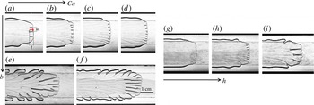
Qualitative results from air injection at various capillary numbers, membrane thicknesses and oil layer depths are shown in figure 2. As anticipated, the section of planar interface over the block undergoes finite-length fingering, and the qualitative evolution of the pattern with
 $Ca$
(
 $h=150~\unicode[STIX]{x03BC}\text{m}$
) is presented in figure 2(a–d) for the thinnest membrane that we used and in figure 2(e,f) for the thickest one. For a given membrane, the fingers become narrower and shorter as
 $Ca$
increases, which is consistent with fingering during the peeling of a strip of viscous adhesive (McEwan & Taylor Reference McEwan and Taylor1966) and the printer’s instability (Rabaud et al.
Reference Rabaud, Michalland and Couder1990). With the thicker membrane, we observe much longer fingers. At fixed
 $Ca$
, the fingers widen and lengthen as the depth of the oil layer
 $h$
increases, as shown by figure 2(g–i). For low
 $Ca$
, large
 $h$
or thick membranes, the front becomes increasingly curved, the patterns become less regular and large-amplitude tip-splitting occurs: the rear meniscus and the front tip of the fingers no longer travel at the same speed, so that their length increases as they propagate. We do not consider these cases in our quantitative analysis, but report them with empty symbols in the subsequent figures. Side branches are also visible in some of the panels in figure 2, and will be discussed later in § 4.
Typical images of the fingering pattern. In (a–d),
 $b=210~\unicode[STIX]{x03BC}\text{m}$
,
 $h=150~\unicode[STIX]{x03BC}\text{m}$
and (a)
 $Ca=0.21$
, (b)
 $Ca=0.56$
, (c)
 $Ca=1.05$
and (d)
 $Ca=1.74$
; in (e,f),
 $b=570~\unicode[STIX]{x03BC}\text{m}$
,
 $h=150~\unicode[STIX]{x03BC}\text{m}$
and (e)
 $Ca=1.61$
and (f)
 $Ca=3.77$
; in (g–i),
 $b=340~\unicode[STIX]{x03BC}\text{m}$
,
 $Ca=0.62\pm 0.02$
and (g)
 $h=100~\unicode[STIX]{x03BC}\text{m}$
, (h)
 $h=130~\unicode[STIX]{x03BC}\text{m}$
and (i)
 $h=240~\unicode[STIX]{x03BC}\text{m}$
.

The average width
 $w$
and length
 $l$
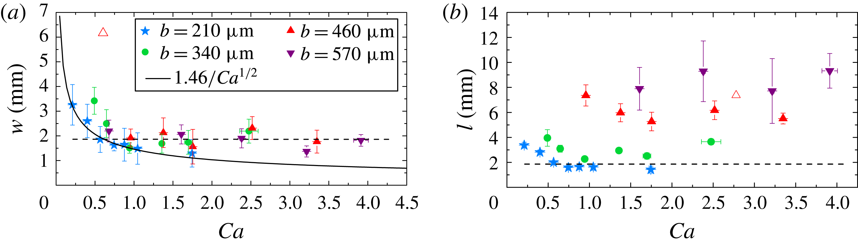
of the constant-length fingers are quantified in figure 3 as functions of
 $Ca$
, for
 $h=150~\unicode[STIX]{x03BC}\text{m}$
. These fingers are never strictly steady, as also found in the printer’s instability when the meniscus is confined between cylinders that are co-rotating with equal velocities (Rabaud et al.
Reference Rabaud, Michalland and Couder1990) – a configuration analogous to the tapered geometry experienced by our steadily propagating front. They widen and split regularly, but maintain a constant average width and length; see movie 1 of the supplementary material available at https://doi.org/10.1017/jfm.2017.468. This behaviour is the main source of uncertainty in our quantitative measurements. For all values of the membrane thickness, the average finger width decreases with
 $Ca$
, towards a constant value that does not depend on the membrane thickness to within experimental resolution (figure 3
a). For each membrane thickness, the average length of the fingers also decreases towards an approximately constant value with
 $Ca$
, but this saturation value increases considerably with the membrane thickness and the fingers are typically longer than they are wide (figure 3
b). Moreover, the value of
 $Ca$
at which saturation is reached increases with the membrane thickness. For the thickest membrane, only the saturated regime could be explored because the elastic peeling front does not occur until relatively large
 $Ca$
(smaller
 $Ca$
resulted in large-amplitude tip-splitting of a curved front).
Evolution of the finger width
 $w$
(a) and length
 $l$
(b) with
 $Ca$
for the four different latex membranes used (
 $h=150~\unicode[STIX]{x03BC}\text{m}$
). The same symbols and colours are used consistently in all subsequent figures. The solid line is a least-squares fit to describe the
 $1/\sqrt{Ca}$
behaviour of
 $w$
at low
 $Ca$
. The dotted guideline present on both figures shows the saturation value of
 $w$
. The empty symbol represents a large-amplitude tip-splitting mode on a curved front.

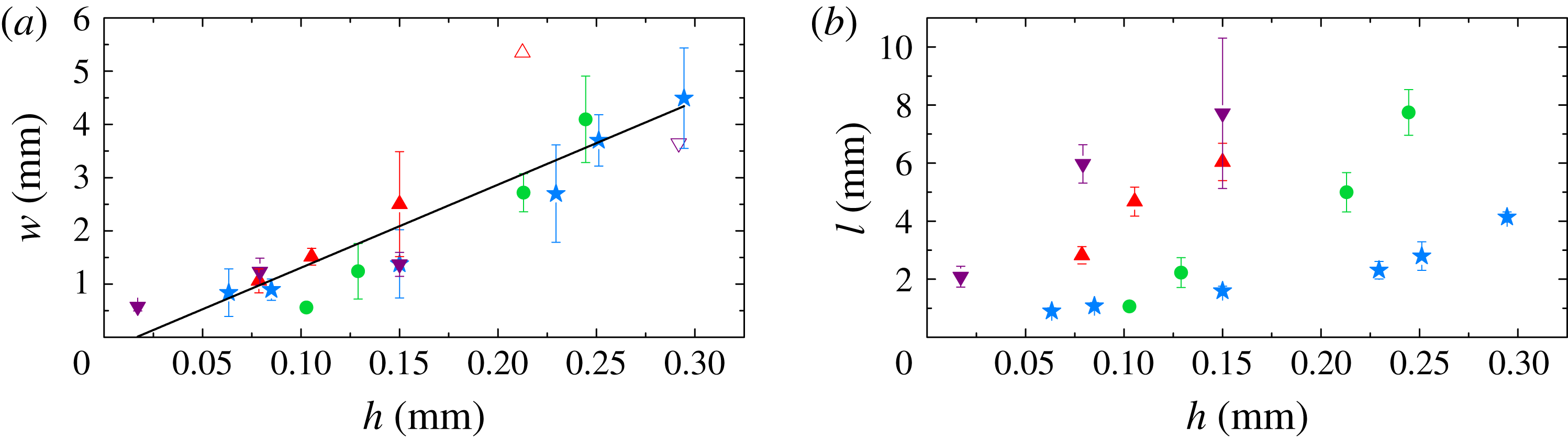
Evolution of the finger width
 $w$
(a) and length
 $l$
(b) in the saturated regime with the thickness of the oil layer. Here,
 $Ca=0.88\pm 0.03$
for
 $b=210~\unicode[STIX]{x03BC}\text{m}$
,
 $Ca=0.62\pm 0.02$
for
 $b=340~\unicode[STIX]{x03BC}\text{m}$
,
 $Ca=1.38\pm 0.05$
for
 $b=460~\unicode[STIX]{x03BC}\text{m}$
and
 $Ca=3.2\pm 0.1$
for
 $b=570~\unicode[STIX]{x03BC}\text{m}$
. The solid line is a linear least-squares fit to all the data for
 $w$
, excluding tip-splitting points (empty symbols).

Because the critical
 $Ca$
for the propagation of a uniform peeling front increases with the membrane stiffness, the data obtained with the softest latex membrane are the closest to onset. The measured finger width scales as
 $1/\sqrt{Ca}$
, as shown in figure 3(a). This scaling and the presence of a saturated plateau further above onset concur with the results obtained for the printer’s instability (Hakim et al.
Reference Hakim, Rabaud, Thomé, Couder, Coullet and Huerre1990; Rabaud, Couder & Michalland Reference Rabaud, Couder and Michalland1991). Moreover, for a given
 $Ca$
chosen in the saturated plateau, the width of the fingers collapses onto a master curve, irrespective of the membrane thickness, and increases linearly with
 $h$
, as shown in figure 4(a). These scalings, although established for fixed
 $h$
or fixed
 $Ca$
, are consistent with the linear stability analysis for a flat interface propagating in a rigid rectangular channel, which predicts that the most unstable wavelength is proportional to
 $h/\sqrt{Ca}$
(Saffman & Taylor Reference Saffman and Taylor1958). This suggests that the average finger width is essentially set by the fluid mechanical instability. Moreover, the fact that
 $w$
remains proportional to
 $h$
in the saturated regime indicates that this scaling still holds away from onset. A linear dependence of the wavelength on the layer depth is also present in instabilities affecting thin layers of soft solids (Chaudhury, Chakrabarti & Ghatak Reference Chaudhury, Chakrabarti and Ghatak2015), but we believe our results to be among the first to demonstrate this property in flowing viscous layers. The length of the saturated fingers (figure 4
b) also increases approximately linearly with
 $h$
, but the gradient increases with the membrane thickness.
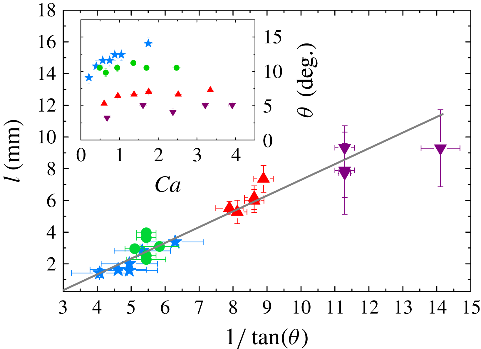
By increasing the membrane thickness (and the transverse pre-tension), the peeling angle
 $\unicode[STIX]{x1D703}$
presented in the inset of figure 5 is reduced. Larger values of the convergent gap angle
 $\unicode[STIX]{x1D703}$
have been shown to have a stabilising effect on the interface, enhancing the contribution of restoring capillary forces and reducing that of destabilising viscous forces, hence delaying the onset of fingering (Al-Housseiny, Tsai & Stone Reference Al-Housseiny, Tsai and Stone2012; Pihler-Puzović et al.
Reference Pihler-Puzović, Illien, Heil and Juel2012). We never observed total suppression of the instability using latex membranes in our compliant channel, because the critical
 $Ca$
needed to propagate the uniform peeling mode is larger than that at the onset of finite-length fingering. However, peeling of a thin silicone membrane (Elastosil from Silex Silicones,
 $b=100~\unicode[STIX]{x03BC}\text{m}$
,
 $E\simeq 600$
kPa, with bending stiffness smaller by a factor of 22 than the thinnest latex membrane) occurred at larger values of
 $\unicode[STIX]{x1D703}$
for a given
 $Ca$
and stabilised a uniformly flat interface, as can be seen in movie 2 of the supplementary material. By consistently varying the peeling angle, we show that
 $\unicode[STIX]{x1D703}$
also has an effect on the fingering pattern: it does not affect the wavelength of the pattern, as shown by the collapse of all data in figure 4(a), but steeper peeling fronts are more stable in the sense that they lead to shorter fingers, while shallower peeling angles promote the growth of long fingers.
Length of the fingers as a function of the peeling angle for
 $h=150~\unicode[STIX]{x03BC}\text{m}$
. The grey line is a linear least-squares fit to the data. The inset gives the variation of the peeling angle with the capillary number for
 $h=150~\unicode[STIX]{x03BC}\text{m}$
.

To quantify the effect of the peeling angle on the finger length, we plot
 $l$
as a function of
 $1/\tan \unicode[STIX]{x1D703}$
in figure 5 for all of the data points shown in figure 3(b). The length of the fingers is approximately proportional to
 $1/\tan \unicode[STIX]{x1D703}$
, indicating that, in all experiments performed with the same liquid-layer thickness, the fingers extend to a constant reopening height, approximately 1 mm for
 $h=150~\unicode[STIX]{x03BC}\text{m}$
. Based on the results in figure 4(b), where the length of the fingers increases with the liquid-layer thickness, we expect that this reopening height will depend on the volume of fluid available to form oil walls between the fingers.
4 Discussion and conclusion
The partially occluded compliant channel offers the possibility of fine control of the local geometry, which enables extensive study of the nonlinearly saturated fingering pattern of a steadily advancing interface in a converging channel. We found that for a given oil thickness,
 $h$
, the width of the fingers is set by the classic (fluid mechanical) linear stability result of Saffman & Taylor (Reference Saffman and Taylor1958) and is approximately proportional to
 $h/\sqrt{Ca}$
. In contrast, the length of the fingers is selected by the peeling angle, which results from a non-trivial (global) interaction between the fluid, the interface and the compliant surface. Thus, although prediction of the peeling angle,
 $\unicode[STIX]{x1D703}$
, from first principles remains a considerable challenge (Jensen et al.
Reference Jensen, Horsburgh, Halpern and Gaver2002; Heil & Hazel Reference Heil and Hazel2011; Peng et al.
Reference Peng, Pihler-Puzović, Juel, Heil and Lister2015; Pihler-Puzović et al.
Reference Pihler-Puzović, Juel, Peng, Lister and Heil2015), once the angle is known, the resulting finger length is simply proportional to
 $1/\tan \unicode[STIX]{x1D703}$
. This first quantification of the effect of the peeling angle on the pattern generated by viscous fingering opens up perspectives for controlled pattern formation. From a fundamental point of view, spanning a range of peeling angles allows us to explore the evolution of the fingering pattern as the channel transitions from compliant (steep peeling front) to rigid (limit of
 $\unicode[STIX]{x1D703}=0$
) boundaries. In the rigid limit, channel expansion no longer restrains the axial extension of the fingers. The divergence of the finger length as
 $\unicode[STIX]{x1D703}$
tends to 0 is a first step towards recovering the classical Saffman–Taylor finger, which grows infinitely long in a rigid uniform channel. Although we could not observe such behaviour, we would expect the constant-depth fingers to interact as they lengthen, as observed in viscous peeling experiments (McEwan & Taylor Reference McEwan and Taylor1966).
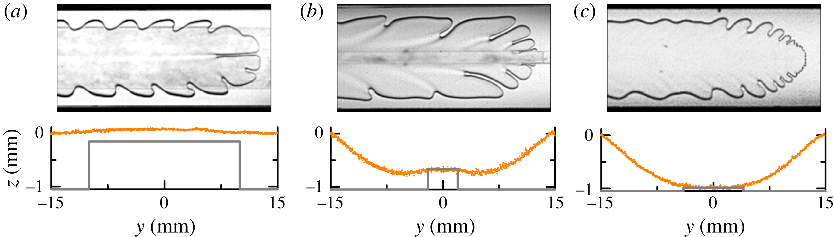
Examples of interfacial patterns that can be generated in an elasto-rigid channel of non-uniform cross-section. The corresponding cross-section prior to air injection is shown below the top view of each pattern (the rigid profile at the bottom of the channel is depicted by the thick grey lines – note that the reference for the vertical axis has been taken at the top of the rigid sidewalls). (a) Transverse depth gradients drive fingering (central block dimensions:
 $20~\text{mm}\times 900~\unicode[STIX]{x03BC}\text{m}$
,
 $Ca=0.43$
); (b) destabilisation far behind the front and fingering in the direction of the strongest depth gradient (block dimensions:
 $4~\text{mm}\times 380~\unicode[STIX]{x03BC}\text{m}$
,
 $Ca=0.71$
); (c) dendritic growth (block dimensions:
 $8~\text{mm}\times 60~\unicode[STIX]{x03BC}\text{m}$
,
 $Ca=0.40$
).

The rich behaviour of the propagating front in our channel allows for the actuation of a broader range of viscous fingering patterns than those obtained on an approximately flat peeling front. A reduction in
 $Ca$
results in curved fronts (figure 6
a), where tip-splitting instabilities form grooves of liquid near the finger tip. These are swept towards the sides of the air finger to form sideways fingers as the tip advances, because the curvature of the front means that the normal velocity at the interface is not aligned with the direction of propagation (Couder Reference Couder, Batchelor, Moffatt and Worster2000). Changes to the height and width of the block, as well as to the level of initial collapse, can be applied to modify the depth gradients in the channel, which promote several types of fingering patterns. Spatially periodic sideways oscillations rely on the transverse depth gradient at the edge of the occlusion (figure 6
a,b). Patterns are shed from the propagating tip, which undergoes oscillations in width driven by the change in cross-sectional curvature of the interface as it crosses the edge of the block. The locally arrested interface is then advected downstream as the finger grows, and periodic oscillations develop on the finger sides. This mechanism has been described in rigid constricted tubes (Pailha et al.
Reference Pailha, Hazel, Glendinning and Juel2012; Thompson, Juel & Hazel Reference Thompson, Juel and Hazel2014; Franco-Gómez et al.
Reference Franco-Gómez, Thompson, Hazel and Juel2016). The growth of fingers can also be observed away from the edge of the block, triggered by the sudden depth change at the edge of the block and amplified in the direction of the strongest depth gradient (figure 6
b). Finally, fingering on the block can couple with the transverse depth gradients to create the dendritic-like pattern illustrated in figure 6(c): the small fingers are amplified by the transverse depth gradient off the block. The amplification of the fingers generated at the edge of the block leads to approximately proportionate growth (fixed width/length ratio) of the fingers, a feature that has been observed in other viscous fingering experiments (Bischofberger, Ramachandran & Nagel Reference Bischofberger, Ramachandran and Nagel2014). The growth of dendrites has been triggered in rigid Hele-Shaw cells by locally perturbing the interface at the finger tip (Couder et al.
Reference Couder, Cardoso, Dupuy, Tavernier and Thom1986), but the selection of the pattern is unexplained; the well-controlled geometry of the compliant channel could enable a more systematic investigation.
Acknowledgements
The authors would like to thank M. Heil for helpful discussions. This work was supported by the Leverhulme Trust under grant number RPG-2014-081.
Supplementary movies
Supplementary movies are available at https://doi.org/10.1017/jfm.2017.468.