
Introduction
Medium carbon high alloyed steel has been widely used as the casting mold material for a long time due to a combination of excellent high-temperature strength, impact toughness, hot cracking resistance, and thermal fatigue [Reference Rafi, Ram, Phanikumar and Rao1]. To further improve the properties of the steels, extensive efforts have been made to investigate the effect of heat treatment on the microstructure and mechanical properties [Reference Zhou, Wu, Shi, Li and Min2, Reference Li, Deng, Wu, Wang and Min3, Reference Luo, Peng, Wang and Wu4, Reference Wei, Wang, Wang, Cui and Chen5]. As a matter of fact, it is the bainite transformation that plays an important role in industrial applications in that the bainitic microstructure has an optimal combination of strength and toughness [Reference Luzginova, Zhao and Sietsma6, Reference Bakhtiari and Ekrami7, Reference Gao, Zhang, Gui, Tan, Bai and Weng8, Reference Tang, Shang, Liu, Guan, Misra and Chen9]. From this point of view, a thorough understanding of bainite transformation kinetics is of significance to control the microstructure and properties of materials.
Earlier, Bhadeshia et al. [Reference Bhadeshia and Christian10] reviewed the bainite transformation in steels including a detailed account of microstructure, chemistry, and crystallography of bainitic ferrite, referring to the effect factors of the bainite transformation such as dislocation density and chemical composition. However, the formation mechanism of the bainite transformation still remains a subject of controversy, although a number of theories have attempted to explain the bainite formation [Reference Fielding11]. Santofimia et al. [Reference Santofimia, Caballero, Capdevila, García-Mateo and García de Andrés12] reviewed and evaluated several kinetic models which are based on the assumptions of the displacive theory of bainite formation. In the displacive theory, the bainite transformation rate was controlled by the rate of bainitic ferrite nucleation, and the models were based on nucleation kinetics. Recently, many modified kinetic models based on the displacive theory for bainitic transformation were developed considering various effect factors to get good qualitative agreement with the experimental results [Reference Chester and Bhadeshia13, Reference Azuma, Fujita, Takahashi and Iung14, Reference Chang15, Reference Hillert, Höglund and Ågren16, Reference Santofimia, Caballero, Capdevila, García-Mateo and Andrés17, Reference Santofimia, Caballero, Capdevila, García-Mateo and Andrés18, Reference Van Bohemen19, Reference van Bohemen and Sietsma20, Reference Sidhu, Bhole, Chen and Essadiqi21, Reference Li, Zhu, Karaman and Arróyave22]. To modify the kinetic model, many researchers have investigated the effect factors of bainite transformation in recent years. Jin et al. [Reference Jin, Min, Zheng and Hsu23] reported that the austenite deformation increased the Bs temperature and decreased the amount of bainite by introducing dislocations. Gong et al. [Reference Gong, Tomota, Harjo, Su and Aizawa24] studied the effect of the preexisting martensite on the bainite transformation using in situ neutron diffraction measurements, and found that the preexisting martensite accelerated the subsequent nano-bainite transformation by inducting dislocations in austenite. Navarro-López et al. [Reference Navarro-López, Sietsma and Santofimia25] and Toji et al. [Reference Toji, Matsuda and Raabe26] also confirmed that preexisting martensite accelerated the following bainite transformation. Chen et al. [Reference Chen, Zhu, Zhao and van der Zwaag27] found that the “transformation stasis” phenomenon during the isothermal bainitic ferrite formation was caused by the diffusion of alloy elements. As reported by Lambers et al. [Reference Lambers, Tschumak, Maier and Canadinc28], the plastic predeformations of austenite could promote the growth of bainite plates by providing additional energy from the plastic deformation. Besides, an important finding in his work was that the undissolved carbides accelerated the bainite transformation eventually. Because the carbides in the matrix led to a lower carbon and chromium content, and the residual carbides constituted additional nucleation sites for the bainite plates. However, there was no direct evidence to support that the carbides were able to act as nucleation sites, which needs further investigation.
Therefore, this study aims at clarifying the effect of carbides on the bainite transformation, in an attempt to provide direct evidence to demonstrate that the carbides are able to act as nucleation sites for the bainite transformation.
Results
The volume fraction of carbides precipitated at 950 °C
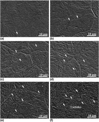
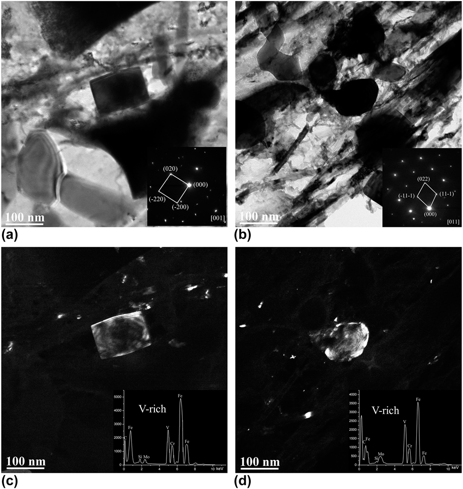
According to the equilibrium phase diagram of H13 hot-work tool steel [Reference Kang, Park, Jung, Kim and Lee29], three kinds of carbides, MC, M7C3 and M23C6, are able to precipitate in H13 hot-work steel below 1000 °C, and in the range from 910 to 1000 °C, only MC carbides were able to precipitate. To exclude the effect of other carbides, it was 950 °C that was selected for the single precipitation of MC carbides. Figure 1 shows the scanning electron microscope (SEM) images of the directly quenched specimens, S0, S2, S5, S10, S30, and S60, with different holding times at 950 °C. The white particles pointed by white arrows, as shown in Fig. 1, are carbides. There existed no cementite in the specimens due to a high content of Cr (5.13 wt%) and Si (0.95 wt%), because the alloying elements Cr and Si suppress the cementite formation [Reference Mesquita, Barbosa, Morales and Kestenbach31]. The carbides were observed to be distributed uniformly in the specimens. The fractions of carbides in specimens were counted using an image analyzer [Reference Kang, Park, Jung, Kim and Lee29, Reference Fujita and Bhadeshia32]. The volume fraction of carbides in S0, S2, S5, S10, S30, and S60 were 0.026%, 0.193%, 0.228% 0.367%, 0.68%, and 1.09%, respectively, which increased with the holding time at 950 °C. To investigate the crystal structure and composition of the carbides, the specimen held at 950 °C for 1 h was observed using transmission electron microscope (TEM). As shown in Fig. 2, the shapes of two big carbides were rectangular and elliptical with a size of about 100 nm. Both of these carbides were identified to be the V-rich MC carbides with face-centered cubic (FCC) crystal structure [Reference Kim, Kang, Son, Lee and Cho33, Reference Angang, Hanjie, Xichun and Mingbo34] based on the selected-area electron diffraction (SAED) and energy-dispersive spectrometer (EDS) analysis.
SEM images of the specimens isothermal at 950 °C for different times (a)–(f): S0–S60, which were held at 950 °C for 0, 2, 5, 10, 30, and 60 min. The carbides in the specimens are pointed by white arrows.

TEM micrographs and EDS of V-rich carbides in S60 specimens: (a, b) bright-field images, and the inserts were the SAED patterns of the carbides; (c, d) are dark-field images, and the inserts in the images are the EDS spectrum of the carbides. The carbides were identified as V-rich MC with an FCC crystal structure.

Morphologies of bainite formed at 350 °C
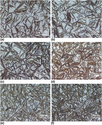
Figure 3 shows the metallographic images of specimens, isothermal at 950 °C for 0, 2, 5, 10, 30, and 60 min followed by a holding at 350 °C for 60 min, taken by optical microscope (OM). After corrosion by LePera reagent, the martensite/austenite (M/A) islands were bright while the needle-like bainite was dark [Reference LePera30], which could be distinguished clearly. As can be seen, the fraction of bainite in the specimens increased with the increasing preexisting VC carbides, and there were not obvious differences in sizes of the bainite needles in these specimens. And the volume fractions of bainite in different specimens, BS0, BS2, BS5, BS10, BS30, and BS60 were, counted using an image analyzer as 0.497, 0.556, 0.604, 0.643, 0.735, and 0.767, respectively. The fractions of bainite in BS60 were obviously more than that in BS0, and the M/A islands in BS60 were divided into smaller blocks.
Microstructures of specimens isothermal at 950 °C for different times and held at 350 °C for 1 h. (a)–(f) specimens S0, S2, S5, S10, S30, and S60.

The bainite transformation kinetics in each specimen
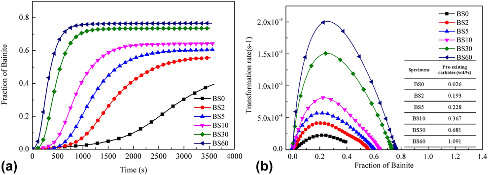
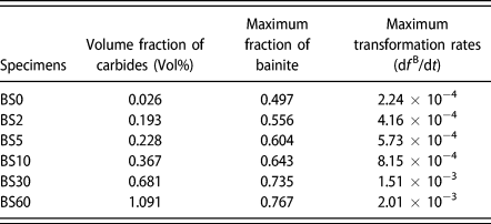
Figure 4(a) shows the length change of each specimen obtained by dilatometer during the isothermal holding stage at 350 °C, and the corresponding fractions of bainite in specimens. As Fig. 4(a) shows, the maximum volume fractions of bainite in different specimens, BS0, BS2, BS5, BS10, BS30, and BS60, were 0.497, 0.556, 0.604, 0.643, 0.735, and 0.767, respectively. As calculated in section “Effect of elements concentration on the bainite transformation”, the volume fractions of the preexisting carbides (precipitated at 950 °C) in BS0, BS2, BS5, BS10, BS30, and BS60 before the bainite transformation were 0.026, 0.193, 0.228 0.367, 0.68, and 1.09%, respectively. The maximum volume fraction of bainite in the specimens increased with the increasing preexisting carbides. Figure 4(b) shows the function of bainite transformation rates df B/dt and the fraction of bainite in different specimens. Because of the autocatalysis of the bainite transformation [Reference Tszeng35, Reference van Bohemen36], the transformation rate of bainite firstly increased, reached a peak value, and then decreased with the increasing fraction of bainite. The maximum transformation rates of specimens S0, S2, S5, S10, S30, and S60 were 2.25 × 10⁻⁴, 4.16 × 10⁻⁴, 5.72 × 10⁻⁴, 8.15 × 10⁻⁴, 1.51 × 10⁻³, 2.01 × 10⁻³ (/s), respectively, and the maximum rate of S60 was about ten times higher than that of the specimen S0 as shown in Table I. The bainite transformation rates were obviously accelerated by the preexisting carbides in the matrix.
(a) Dilatometric curves tested by dilatometer and the fraction of bainite measured using SMM of different specimens as a function of isothermal holding time at 350 °C. (b) The transformation rates df B/df of different specimens as a function of isothermal holding time at 350 °C. The insert is the volume fraction of the preexisting carbides in the specimens.

The maximum fractions and the maximum transformation rates of bainite in different specimens. The maximum fraction and maximum transformation rates of bainite increased with the increasing volume fraction of preexisting carbides in the matrix.

The role of preexisting carbides in the bainite formation process
To investigate the role of carbides in the process of bainite formation, a specimen was austenitized at 1100 °C for 30 min, then quickly cooled to 950 °C, held for 60 min to precipitate carbides, finally cooled to 350 °C, held for only 30 s, and then quenched to room temperature (this specimen was named BSI). Under this condition, the bainite transformation was interrupted just at the beginning. As a result, the initial acicular bainitic ferrites formed at the nucleation sites were kept in this specimen.
The specimen BSI was etched using 0.5% hydrochloric acid solution, because bainite was etched more easily, it could be distinguished under SEM. Figure 5(a) shows the morphology of BSI observed using SEM. As can be seen, the etched acicular pointed by long arrows are bainitic ferrites [Reference Gao, Zhang, Gui, Tan, Bai and Weng8, Reference Liu, Miyamoto, Yang and Furuhara37], which formed at positions beside the carbides (pointed by the short arrow), and this typical area was enlarged as shown in Fig. 5(b). The carbides and acicular bainite in specimen BSI were also confirmed by electron back scattered diffraction (EBSD). Figure 5(c) shows the SEM-BEI image, acicular bainite ferrites, and VC particles distributed uniformly, and a typical area is highlighted using a rectangle. The carbide and acicular bainite are pointed by long and short arrows, respectively. Figure 5(d) shows the phase map of BSI, in which the matrix is the phase with a bcc structure, and the small particles are VC carbides. In the rectangle, a typical morphology of bainite growing from a carbide core was observed, which corresponded to the results shown in Fig. 5(a).
SEM, EBSD, and TEM images of specimen BSI held at 350 °C for 30 s, (a) the SEM image of BSI, (b) is the enlarged image of (a), and the bainite and carbides are pointed by long and short arrows separately. (c) SEM-BEI image of BSI, (d) EBSD phase map of BSI, and the matrix and small particles represent the bcc structure and carbide FCC structure, respectively. (e) The dark-field image of carbides, (f) the dark-field image of bainite and the insert is the SAED pattern.

TEM characterization of BSI is shown in Fig. 5(e), and a primary bainite lath nucleating at the interface of carbide and matrix was observed. As can be seen in Fig. 5(e), carbides were observed in the matrix and confirmed as V-rich MC carbides with an FCC crystal structure by the SAED pattern as shown in the insert. And a bainite lath was observed growing beside the carbide. Figure 5(f) shows the dark field image of the bainite lath.
Discussion
Effect of element concentration on the bainite transformation
As shown in Fig. 4, the bainite transformation rates increase with the increasing carbides in the specimens. The effect of carbide precipitation on the bainite transformation kinetics was investigated according to the nucleation rate under the assumption that the kinetics of bainite transformation follows the displacive mechanism [Reference Santofimia, Caballero, Capdevila, García-Mateo and Andrés17, Reference Van Bohemen19, Reference van Bohemen and Sietsma20, Reference Sidhu, Bhole, Chen and Essadiqi21, Reference Garcia-Mateo and Bhadeshia38]. Under this assumption, the transformation rates are only related to the nucleation rates. The relationship between the transformation rate and the nucleation rate can be given as [Reference Navarro-López, Sietsma and Santofimia25]:
 $${{{\rm{d}}{f^{\rm{B}}}} \over {{\rm{d}}t}} = {{{\rm{d}}N} \over {{\rm{d}}t}}{V_{\rm{b}}}\quad ,$$
where f B is the fraction of bainite, N is the nucleation sites for bainite per unit of volume, t is the time, and V b is the average volume of bainite subunits. There have been many studies of the volume of bainite subunits, and according to the work of Bhadeshia [Reference Chang and Bhadeshia39], this thickness was assumed to be 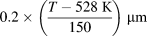 $0.2 \times \left( {{{T - 528\;{\rm{K}}} \over {150}}} \right)\;\mu {\rm{m}}$ based on the experimental data. The subunit volume can be described as [Reference Navarro-López, Sietsma and Santofimia25]:
 $${V_{\rm{b}}} = 20{\left( {{{T - 528\;{\rm{K}}} \over {150}}} \right)^3}\;\mu {{\rm{m}}^3}\quad .$$
Because the bainite transformation temperature was 350 °C in the experiments, the value of V b can be calculated, V b = 5.08 × 10⁻¹⁸ m3, and then the  ${{{\rm{d}}N} \over {{\rm{d}}t}}$ can be calculated using
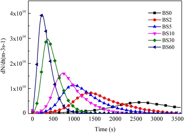
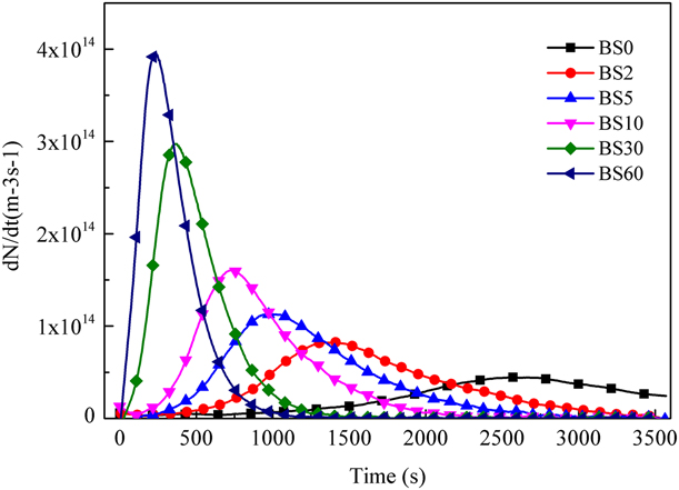
 ${{{\rm{d}}N} \over {{\rm{d}}t}} = {{{\rm{d}}{f^{\rm{B}}}} \over {{V_{\rm{b}}}{\rm{d}}t}}$ according to Fig. 4(a); the nucleation rates for bainite transformation in different specimens are shown in Fig. 6.
Evolution of nucleation rates for the bainite transformation of different specimens held at 350 °C. The nucleation rates in the specimens S2, S5, S10, S30, and S60, with preexisting carbides were larger than that in the specimen S0 without preexisting carbides.
Since all of the specimens were austenitized under the same condition holding at 1100 °C for 30 min, the initial austenite grain size of them was almost the same and the effect of grain size on the bainite transformation kinetics [Reference Lee, Park and Lee40] could be neglected. Here, the bainite transformation kinetics is expressed based on the model developed in Ref. Reference Bohemen and Hanlon41 as:
 $${{{\rm{d}}{f^{\rm{B}}}} \over {{\rm{d}}f}} = \left( {1 - {f^{\rm{B}}}} \right)\left( {1 + \lambda {f^{\rm{B}}}} \right)\kappa \quad ,$$
where f B is the bainite fraction, λ is the autocatalytic parameter of bainite nucleation at bainite-unstable austenite interfaces, here λ is a fitting parameter, and κ is a rate parameter depending on temperature.
 $$\kappa = {{kT} \over h}{{Z\delta } \over {{D_{\rm{A}}}}}\alpha \exp \left( {{{{K_1}\Gamma } \over R}} \right)\left( {{T_{\rm{h}}} - T} \right)\exp \left( { - {{{Q_{\rm{b}}}} \over {RT}}} \right)\quad .$$
where k is Boltzmann constant, h is Planck constant, Z is a geometrical factor, δ is the effective thickness of an austenite boundary, D A is the parent austenite grain diameter, α is a kinetic parameter describing the rate of bainite formation, Q b is the effective activation energy, T h is the highest temperature for the nucleation of a displacive transformation, and Γ represents the derivative of the maximum driving force ΔG m with respect to temperature. K 1Γ can be calculated using equation: K 1Γ = (169.8 kJ/mol − Q b)/(705 K). Q b and T h can be calculated using the following equations from Ref. Reference HajyAkbary, Sietsma, Miyamoto, Furuhara and Santofimia42. T h was fitted by the calculated data of JMatPro.
 $${Q_{\rm{b}}} = 89{\rm{X}}_{\rm{c}}^{{\rm{UA}}} + 10{{\rm{X}}_{{\rm{Mn}}}} + 12{{\rm{X}}_{{\rm{Si}}}} + 2{{\rm{X}}_{{\rm{Cr}}}} + 1{{\rm{X}}_{{\rm{Ni}}}} + 29{{\rm{X}}_{{\rm{Mo}}}}\quad ,$$
 $${T_{\rm{h}}} = 1338 - 198{{\rm{X}}_{\rm{C}}} - 91{{\rm{X}}_{{\rm{Mn}}}} - 15{{\rm{X}}_{{\rm{Si}}}} - 73{{\rm{X}}_{{\rm{Cr}}}} - 36{{\rm{X}}_{{\rm{Ni}}}} - 87{{\rm{X}}_{{\rm{Mo}}}}\quad ,$$
where the Xi is the concentration of element i in weight percent.
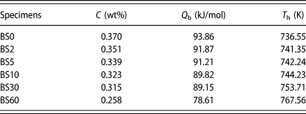
The calculated Q b and T h of different specimens are listed in Table I. Q b decreased from 93.86 kJ/mol to 78.61 kJ/mol, while T h increased from 736.55 to 767.56 K.
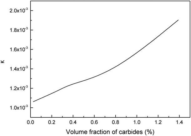
As shown in Table II, the carbon concentration in the matrix decreased after the precipitation of VC carbides [Reference Lambers, Tschumak, Maier and Canadinc28], resulting in the decrease in Q b and the increase in T h. And accounting to Eq. (4) both of these two factors made the rate parameter κ increase as shown in Fig. 7. As a result, the bainitic transformation rate was accelerated.
Q b and T h calculated according to Eqs. (5) and (6) of different specimens before the bainite transformation. The effective activation energy Q b decreased, while the highest temperature T h for the nucleation of a displacive transformation increased with the decreasing carbon concentration in the matrix.

Change of kinetics parameter κ with the increasing carbides in the specimens. The value of κ increased with the increasing volume fraction of carbides precipitated at 950 °C.

At the end of the bainitic transformation, the relation between the carbon content and volume fraction of bainite can be expressed as [Reference Santofimia, Caballero, Capdevila, García-Mateo and Andrés17]:
 $${V_{\max }} = {{{x_{{T_0}}} - \bar{x}} \over {{x_{{T_0}}} - {x_{\rm{B}}}}}\quad ,$$
where V max is the maximum volume fraction of bainite,  ${x_{{T_0}}}$ is carbon content of the residual austenite,
 $\bar{x}$ is the nominal carbon content of the material, and x B is the paraequilibrium value of carbon content in the bainitic ferrite. The precipitation of VC carbides before the bainite transformation would decrease the carbon content of the austenite matrix. Based on Eq. (7), the maximum volume fraction of bainite would increase with the decreasing carbon content, which agrees well with the observed results shown in Fig. 6.
The effect of carbides on bainite transformation
The effect of carbides precipitation on the bainite transformation kinetics came from two aspects. Firstly, the matrix composition would change after the carbides precipitation, which had an effect on the active energy of the bainitic nucleation [Reference Gong, Tomota, Harjo, Su and Aizawa24]. Secondly, the carbides played an important role in acting as nucleation sites for bainite, which accelerated the transformation rate.
Generally, the nucleation would start at the boundary of original austenite grain, due to the high interface energy [Reference Ravi, Sietsma and Santofimia43]. However, the preexisting carbides provided more interfaces between carbides and austenite matrix. As shown in Fig. 5, these sites acted as the new nucleation sites for the bainite transformation, which accelerated the transformation rate.
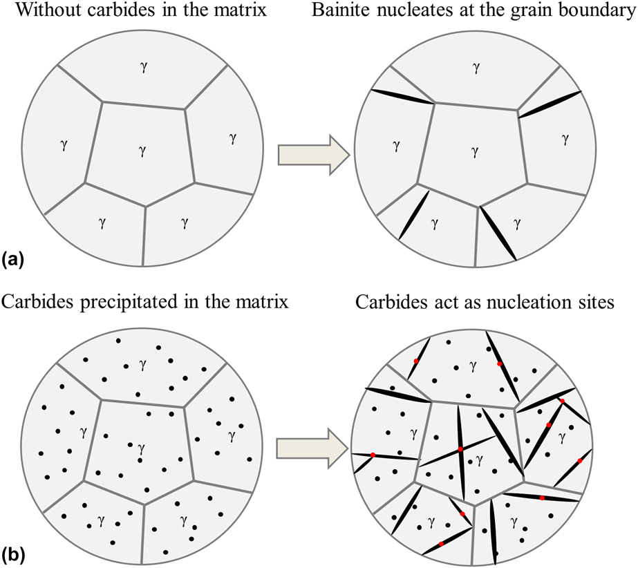
To clarify the effect of carbides on the bainite transformation, a sketch diagram of the isothermal transformation at 350 °C is shown in Fig. 8. The black needle-like laths represent bainitic ferrite, and the black particles are the preexisting VC carbides. Figure 8(a) shows the formation process of bainitic ferrites in the specimens without carbides, in which bainite nucleated mainly at the grain boundary, while in the specimens with the preexisting carbides in the matrix, bainite would nucleate not only at the grain boundary but also at the new nucleation sites created by the carbides as shown in Fig. 8(b).
Schematic of the bainite transformation at the beginning of the isothermal holding at 350 °C (a) without preexisting carbides in matrix, and (b) with preexisting carbides in the matrix. The black particles represent the preexisting carbides and the black acicular particles represent the bainite.

Conclusion
The carbides precipitated during holding at the austenite region were identified and the effect of carbides on the bainite transformation kinetics of H13 steel has been investigated via isothermal treatments at the bainite region. Following are the main conclusions obtained.
(1) The carbides precipitated at 950 °C were V-rich MC with a size of about 100 nm, and observed to be distributed uniformly in the specimens.
(2) The maximum volume fraction of bainite formed at 350 °C increased with the increasing amount of the preexisting VC carbides.
(3) The preexisting VC carbides decreased the C and V contents of the matrix, which decreased the active energy and raised the highest temperature for nucleation of the bainite transformation; as a result, the bainite transformation rate was accelerated.
(4) The preexisting VC carbides in the matrix had a strong accelerating effect on the subsequent isothermal transformation kinetics by creating a number of nucleation sites for the bainite transformation.
Experimental procedure
The chemical composition of the steel (H13) under investigation was Fe–0.37C–0.83V–5.13Cr–0.36Mn–1.23Mo–0.95Si (wt%). Cylinder specimens with length of 10 mm and diameter of 4 mm were machined. All the specimens were heat-treated in a DIL 805A/D dilatometer (produced by TA Instruments, New Castle, Delaware). The specimens were placed between two pushing rods, heated by an induction coil, and cooled by nitrogen gas. The length changes of the specimens were recorded by a linear variable displacement transducer. The specimens were austenitized at 1100 °C for 30 min, then rapidly cooled to 950 °C at 20 °C/s and held at this temperature for 0, 2, 5, 10, 30, and 60 min. Then, they were cooled from 950 °C to 350 °C at 20 °C/s and held at 350 °C for 60 min (for the isothermal bainitic transformation), and then cooled to room temperature at 20 °C/s. The specimens were named BS0, BS2, BS5, BS10, BS30, and BS60. Accordingly, all specimens were austenitized at 1100 °C since the original carbides would be dissolved at this temperature, before the bainite transformation at 350 °C; the specimens were held at 950 °C for different times to precipitate the VC carbides. It was 950 °C that was selected for the single precipitation of MC carbides because only the MC carbides were able to precipitate at this temperature according to the equilibrium phases diagram calculated using Thermo-Calc [Reference Kang, Park, Jung, Kim and Lee29].
To calculate the volumetric fractions of carbides precipitated at 950 °C, another group of specimens without bainite was prepared. The specimens were austenitized at 1100 °C for 30 min, then rapidly cooled to 950 °C at 20 °C/s and held at this temperature for 0, 2, 5, 10, 30, and 60 min, after which they were directly cooled to room temperature at 20 °C/s. The specimens in this group were named S0, S2, S5, S10, S30, and S60.
The specimens directly quenched from 950 °C were etched by a mixed solution of picric acid (4 g), ethanol (100 mL), and a few drops of concentrated hydrochloric acid (1 mL), and the specimens held at 350 °C were etched using LePera reagent [Reference LePera30]. The morphology of specimens were observed using OM and SEM in both the secondary electron imaging (SEI) and the backscattered electron imaging (BEI) modes. The phase compositions were confirmed by EBSD. The diffraction pattern and crystal structure of carbides were analyzed using a TEM. TEM specimens were polished by the solution of perchloric acid (5% perchloric acid and 95% alcohol) using an automatic twin-jet electropolisher produced by Struers, Shanghai, China. The volume fraction of carbides in the specimens was counted by an image analyzer. The bainite volume fraction of BS60 was counted using an image analyzer, and the bainite volume fraction in the other specimens was calculated using level rule method.
Acknowledgment
This work was financially supported by the National Basic Research Program of China under Grant No. 2011CB12904.