

Introduction
In North Africa, a broad array of human-made features of diverse shapes, dimensions and functions can be found on solid rocks (Gabriel Reference Gabriel, Krzyżaniak, Kroeper and Kobusiewicz2003). These include cupules or cupule-like features (cf. Bednarik Reference Bednarik2008), grinding grooves and hollows, hooks to hang objects, thread-through holes and pegs, and “rock gongs” (e.g. Kuhlmann Reference Kuhlmann2002: 133–37; Kleinitz Reference Kleinitz2004; Kuper et al. Reference Kuper, Leisen, Riemer, Förster, Krause, Büttner, Darius and Kindermann2010: 23 & fig. 26; Suková Reference Suková2011; Lenssen-Erz Reference Lenssen-Erz2015: 21 & fig. 4). They are usually recorded by epigraphists or rock-art researchers in the scope of their surveys, although they rarely fall within the sphere of epigraphy or iconography. Archaeologists, on the other hand, have so far devoted only minimal systematic attention to these features (e.g. Francaviglia Reference Francaviglia2005). This is surprising, given that these features represent the remains of deliberate human actions and offer great archaeological potential. Unfortunately, determining the age and function of these features is challenging, as they often have little direct association with other archaeological evidence at the site. This does not, however, negate the potential value of such features. This is the case with a specific type of drilled holes recorded by the Czech archaeological mission at the site of Sphinx (SBK.W-60) at Jebel Sabaloka at the Sixth Nile Cataract in central Sudan, where a functional interpretation can be proposed.
The site and the evidence
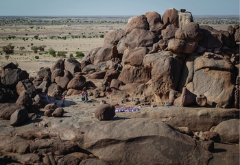
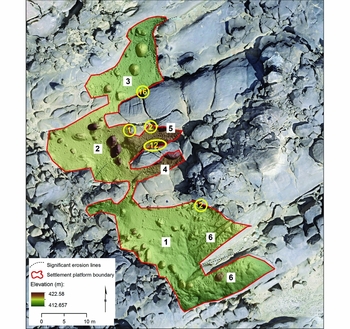
The site of Sphinx (SBK.W-60) is located on the west bank of the Nile, in the north-western foothill zone of Jebel Sabaloka. It is situated at the top of a hill formed of granite rocks and boulders (around 425m asl), the shape of which gives the site its name (Figure 1). The site is somewhat difficult to approach, as it is protected by a ‘rampart’ formed by surrounding rocks. Its elevated position, about 15m above the surrounding landscape, and the excellent view it commands, makes the site location quite strategic. The roughly crescent-shaped settlement platform (approximately 940m2) is divided naturally into southern, central and northern parts. Perpendicular to the central part are two tongue-shaped areas gently sloping from east to west: the southern and northern shelters (Figure 2). The site abounds with surface and subsurface finds of pottery, lithics and other artefacts datable to the Khartoum Mesolithic (c. 9000–5000 BC). During this period, it served as a core settlement and also as a collective burial ground for sedentary or semi-sedentary hunter-fisher-gatherers (Suková & Varadzin Reference Suková and Varadzin2012; Varadzinová Suková et al. Reference Varadzinová Suková, Varadzin, Bajer, Lisá, Pacina and Pokorný2015). A small number of surface finds dating to the Meroitic (c. 300 BC–AD 350) or Post-Meroitic (c. AD 350–550) and Funj (c. AD 1500–1800) periods have also been recorded.
Site of Sphinx (SBK.W-60), viewed from the south-east (photograph by Petr Pokorný).

Site of Sphinx, digital terrain model: 1–3) southern, central and northern parts of the settlement platform; 4) southern shelter; 5) northern shelter; 6) concentrations of grinding hollows; yellow) locations and numbers of drilled holes (plan by Jan Pacina, drawing by Ladislav Varadzin).

The granite surfaces at Sphinx have been affected by diverse natural processes that have left various marks and features. Quite distinct from the natural remains are two types of features that are undoubtedly anthropogenic in origin. The first are the numerous grinding hollows or rock mortars located on exposed horizontal rock surfaces (Figure 2: 6). Features of this type are found in large concentrations not only at Jebel Sabaloka, but throughout north-east Africa and beyond (Bednarik Reference Bednarik2008: 69).
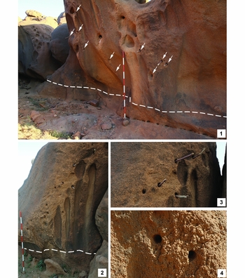
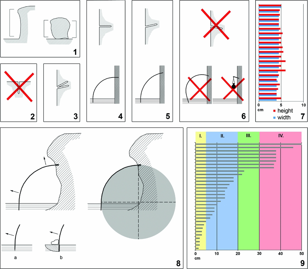
The second type consists of 33 holes found on the vertical faces of rocks or immovable boulders (Figure 3: 1–4). These holes vary in depth from 15–500mm, but are otherwise relatively uniform in character (Figure 4: 1–9). They are distinguished by having a regular cylindrical shape with visibly smooth sides, a reasonably standardised diameter of 40–50mm, and a pointed end. They were undoubtedly produced by drilling, probably using a stone or metal point (although no traces of metal were noted) attached to a wooden staff. Use of abrasives cannot be discounted. These features never occur on horizontal surfaces (Figure 4: 1–2). The holes extend either horizontally or with a slightly upward inclination into the vertical rock surface, but never downwards (Figure 4: 4–6). In one isolated case, two holes were drilled at different angles from the same spot (Figure 4: 3).
Examples of artificial holes (some with wooden sticks inserted during field research): 1) northern shelter, southern wall; 2–3) northern part of the settlement platform; 4) southern part of the settlement platform; dashed line) the uppermost of the weathering lines representing the maximum height of the terrain in the past (photograph by Ladislav Varadzin).

Overview of data: 1) the holes always occur on the vertical walls of rocks and boulders only; 2) they never occur vertically on horizontal surfaces; 3) there is a singular case of two holes drilled from one spot; 4–6) the holes are drilled horizontally or slightly upwards, never downwards; 7) comparison of the widths and heights at the mouths of some holes; 8) hypothetical building reconstruction—the poles with one end anchored into the rock and the other end either (a) pushed into the ground or (b) placed in a dug-out pit and recovered by earth, with the bend of the pole approximately circumscribing a circle; 9) division of the holes into four groups according to their depth (drawing by Ladislav Varadzin).

The holes are positioned at a height of about 1.3–3.2m above the present-day ground surface. Within the site they form five groups, with the largest groups situated on the southern wall of the northern shelter (12 holes) and on the southern side of the northern part of the settlement platform (16 holes) (Figure 2). Similar holes have been recorded at five other locations in the western and north-western foothill zone of Jebel Sabaloka. Elsewhere in North Africa, however, such features have not hitherto been formally reported, although a number of published and unpublished photographs suggest their existence in Ennedi and Tibesti in Chad, at Gilf Kebir in Egypt, and at Musawwarat es-Sufra in Sudan (Huard Reference Huard and Kuper1978: figs 2 & 4; Simonis et al. Reference Simonis, Faleschini and Negro1994: fig. 4; Lenssen-Erz Reference Lenssen-Erz2015: fig. 4). The investigation and interpretation of such holes at Sphinx form the main focus of this paper.
Functional interpretation
The drilling of holes into granite must have represented a task of considerable difficulty. Although we cannot exclude the possibility that the holes were created in connection with some ritual or magical activity, there is nothing to suggest such an interpretation. It thus falls beyond the scope of evidentiary reasoning and, for that reason, is not pursued further in this paper. The fact that the design, orientation and distribution of the holes obey certain rules (see below) suggests, on the contrary, that they were made to fulfil some kind of practical function.
Recording and analyses of the holes prompted the discussion of several hypotheses. Did they, for example, represent holes for pegs from which to hang objects (cf. Berger Reference Berger2010), or for ladders and scaffolding (cf. Riemer & Bartz Reference Riemer, Bartz and Kuper2013)? Such uses are, however, contradicted by the small diameter of the holes, their depth and inclination, and a lack of reasonable justification for the existence of such fittings at the places in question. The most practical explanation was to view the holes as the remains of built structures made of wooden components affixed to the rocks.
We decided to test this hypothesis using a virtual experimental building project that is based on detailed documentation of both the holes and the rock walls (using photogrammetry, 3D models, photographs and measurements). In the reconstructions presented below, attention is focused on the two largest groups of holes recorded on the southern wall of the northern shelter (structure 1) and in the northern part of the settlement platform (structure 2).
In the absence of mortar or metal anchoring elements, drilled holes appear to constitute a simple but effective method for attaching installations firmly to a rock. The size and shape of the holes, however, would permit only slender building components with a diameter of no more than 40–50mm. We suppose the use of pliable wooden poles made of branches or roots, one end of which was inserted into the holes in the rock (where they could have been further secured using some kind of fill), with the other end pushed into the ground or set in a pit dug in front of the rock wall. Bending the poles created a tension that held them in place. With an even width and homogeneous material, the arc of the poles was likely to circumscribe a circle (Figure 4: 8). This allows an estimation of the approximate pole length and the place where each pole entered the ground.
In our reconstruction, we attach key importance to the supposition that the poles anchored in the rock served a supporting function, firmly securing the construction in place, while providing support for additional building materials. It can be expected that the deepest holes held poles taking the greatest strain, and these therefore represent the most crucial structural elements. In contrast, the shallow holes may have served as attachment sites for subsidiary structural components or internal partitions. Nevertheless, the possibility that some of the shallow holes remain unfinished cannot be ignored. Accordingly, we have divided the holes into four categories (Figure 4: 9) with depths equating to: (I) less than 50mm (yellow); (II) 50–200mm (blue); (III) 200–300mm (green); and (IV) exceeding 300mm (red).
The present-day terrain at the site is situated several tens of centimetres below the past ground-surface level (Varadzinová Suková et al. Reference Varadzinová Suková, Varadzin, Bajer, Lisá, Pacina and Pokorný2015). This lowering of the surface was caused particularly by wind erosion, accelerated with the onset of Middle Holocene climatic aridity (e.g. Kuper & Kröpelin Reference Kuper and Kröpelin2006). The approximate maximum height of the ground surface during climatically favourable periods of the Early and Middle Holocene is indicated by weathering lines on the rocks that enclose the settlement platform. In the northern shelter and in the northern part of the site, the former ground surface was as much as 60cm above the modern surface. Although the reconstructions used the highest proposed (i.e. of the Early and Middle Holocene) level of the terrain (Figure 3: 1–2), the authors do not claim that the holes may not date to later periods when the terrain level was already lowered. Given the circular bend of the poles, the reconstructed ground-plan of both structures is smaller than it would be if based on the modern terrain level.
Structure 1 (northern shelter)
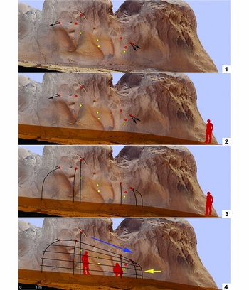
The hypothetical reconstruction of structure 1 (Figure 5) made use of 12 holes spread over the southern wall of the northern shelter. The ground surface below the rock wall featured a cluster of medium-sized granite fragments that were otherwise uncommon at the site, both in terms of quantity and arrangement (in 2014 the cluster was disturbed by looters in search of valuables), and a comparably large quantity of ground stone artefacts. Lithics and potsherds were also present, but in greatest abundance along the northern side of the shelter. Here, several dozen sherds of Funj date (c. AD 1500–1800) were also collected. Due to deflation and water erosion, the surface finds had been redeposited both vertically and horizontally, and were rarely in their original position.
Northern shelter, southern wall, projection into a vertical plane derived from 3D model, viewed from the north: 1) position of the holes (lateral directions indicated by black arrows) and their depths (yellow, blue, and red—categories I, II and IV); 2) reconstruction of the maximum level of the terrain (in brown) prior to deflation (height of the figure = approximately 170cm); 3) reconstruction of the position of supporting poles; 4) possible installation of horizontal elements; the blue arrow indicates the direction of rainwater drainage; the yellow arrow indicates an entrance (3D model by Jan Pacina, drawing by Ladislav Varadzin).

The drilled holes were situated above or outside the natural recesses in the lower section of the rock wall (Figure 5: 1), and fall into three depth categories (I, II and IV). It is significant that the deepest holes (category IV distinguished in red—more than 300mm) constitute the uppermost in the entire set. We assume that it was into these holes that the main supporting poles were inserted. The westernmost and easternmost holes were drilled at an angle, meaning that the poles at both ends projected laterally from the rock wall (Figure 5: 1–3). With the supporting poles in place, horizontal components could be easily attached using various binding materials. Thus a basic wooden skeletal framework was created (Figure 5: 4) that was subsequently covered by roofing. The resulting structure featured an oval ground-plan approximately 6.2 × 2.3m, with the long axis aligned east–west. It was comparatively large—its floor area can be estimated at around 17m2 (including the area of the recesses). It had a vaulted roof, high enough (2.3m) inside for an adult to stand comfortably upright.
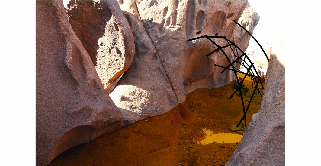
The reconstruction shows that the upper purlin slopes downwards conspicuously at the western (right) side. This design may have served to direct rainwater from the roof onto the slope below the structure. The western side is the most probable location for a tunnel-shaped entrance, with a height of at least 1.1m (or up to 1.8m when measured from the modern surface). Placing an entrance here would have had several advantages. First, it would offer an easy approach from the only access path to the northern shelter; second, its placement would preclude rainwater ingress through the entrance; and third, it would be placed away from the prevailing winds, which usually blow east–west. The method of closing the structure on the left (eastern) side is not clear (Figure 6). The structure could not, however, have extended much farther east, as the rock face trends sharply inward. Stones or earth could have been placed around the base of the structure to tighten the covering. Drainage around the base of the structure could have been easily achieved by a concentric ditch or embankment, evidence for which, however, has not survived.
Northern shelter, view from the north-east: reconstruction of the wooden skeletal framework of structure 1 on the former terrain prior to deflation (in brown) (photograph and drawing by Ladislav Varadzin).

Structure 2 (northern platform)
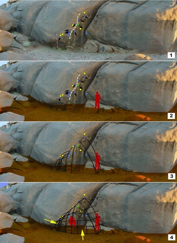
The hypothetical reconstruction of structure 2 (Figure 7) made use of 16 holes located on two adjacent boulders in the middle of the southern side of the northern settlement platform. The surface below the boulders was littered with lithics, potsherds and other Mesolithic finds. As in the previous case, most of the surface finds had been redeposited both vertically and horizontally. The terrain sloped gently from west–east (Figure 2).
Southern side of the northern part of the settlement platform, view from the north-west: 1) position of the holes and their directions (black arrows) and depths (yellow, blue and green—categories I, II and III); the dashed line indicates the division of the holes based on their orientation to the east (left) and west (right); 2) reconstruction of the maximum level of the terrain prior to deflation (height of the figure = approximately 170cm); 3) reconstruction of the position of the vertical poles; 4) possible installation of horizontal elements; the yellow arrows point to the possible locations of an entrance (photograph and drawing by Ladislav Varadzin).

The arrangement of the holes differs from structure 1 in that nearly all of them (15) are distributed along a steep oblique line that runs parallel to the edge of one of the boulders (Figure 7: 1). They differ also in the depth categories to which they are assigned—category IV is absent; there is only one hole in category III (green); and the holes in category II (blue) are twice as numerous as those in category I (yellow). The shallower holes could only provide subtle anchoring of supporting poles, as compared with structure 1, although this was counterbalanced here by their higher quantity and denser arrangement. The holes can be divided into two groups, based on their orientation. To the right of the dashed line shown in Figure 7: 1–2, the holes are drilled at an angle and point to the west (right). To the left, the holes are drilled either perpendicular to the rock face, or laterally at an angle directed to the east (left). The orientation affected the position of the supporting poles in our reconstruction (Figure 7: 3). Horizontal elements could be easily attached to the vertical poles, with some possibly inserted into the natural clefts, where they could be further secured by pegs (Figure 7: 4). The reconstructed structure featured a roughly semi-circular ground-plan and a dome-shaped roof. As with structure 1, it was comparatively large (approximately 3.9 × 2.3m), with a floor area estimated at about 7.5m2, and an internal height (1.8m) sufficient for an adult to stand upright.
The entrance to structure 2 could have been located either in the free space created in the centre between the vertical poles, or beside the rock wall on the left side of the structure. The latter option would mirror structure 1 in its tunnel-like shape, a height of around 0.6m and with its location downslope, preventing surface water ingress.
Verification
Experimental procedures in archaeology can support hypotheses, rather than confirm them. Subsequently, the reconstructions presented above can only suggest that the holes at Sphinx may have performed an architectural function. Due to either wind erosion or looting, no artefactual evidence has survived (Varadzinová Suková et al. Reference Varadzinová Suková, Varadzin, Bajer, Lisá, Pacina and Pokorný2015: 142–47; Varadzinová et al. Reference Varadzinová, Varadzin, Čuláková, Řídký and Sůvová2016) that would unequivocally corroborate this hypothesis. It should, however, be stressed that only constructions similar to the structures proposed can provide a coherent explanation for all the characteristic features of the holes:
-
1) They are only located on vertical rock faces or immovable boulders (Figure 4: 1).
-
2) They are never found on horizontal surfaces (Figure 4: 2).
-
3) They are always drilled horizontally or with their terminal pointing obliquely upwards (Figure 4: 4–5), never downwards (Figure 4: 6). This probably prevented overstraining the poles and the accumulation of rainwater at the interface of roofing and rock. Moreover, the direction of hole-drilling does not support their use for pegs—an opposite drilling angle would be expected for such a purpose.
-
4) The isolated occurrence of a hole drilled twice at different angles (Figure 4: 3) may be the result of re-installation of a particular pole that, upon completion of the construction, was found not to produce the desired structural shape.
-
5) The diameter of all holes is very similar (Figure 4: 7), as they were created according to the same design.
-
6) The smaller width to height measurement ratios of the hole mouths (Figure 4: 7) may indicate increased vertical tension of the bent supporting poles (Figure 4: 8); this may be the result of abrasion of the hole mouths in a vertical direction by intermittent high winds.
-
7) Diversity in hole depth (Figure 4: 9) can be explained by different strength requirements for securing the individual anchoring components.
-
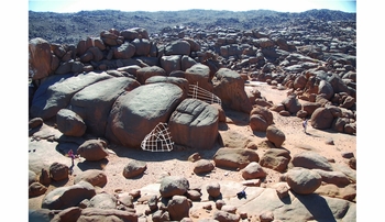
8) Both reconstructed structures are situated in the only two places at the site shaded by rocks throughout the day (Figure 8). If one wanted to camp at the site today, no better place for shelter could be found.
Figure 8.Structures 1 and 2 erected at the most shaded locations at the site (viewed from the north) (photograph and drawing by Ladislav Varadzin).


Dating
The holes themselves cannot be dated. We can only state that they are almost certainly not recent, as they are patinated and their mouths are weathered. Surface and subsurface finds of pottery (several thousand fragments analysed so far), lithics (several tens of thousands analysed so far), and other artefact types retrieved during excavation place the main occupation of the site within the Khartoum Mesolithic. This time range is supported by a series of 15 AMS 14C measurements that span the period 8276–5002 cal BC (Varadzinová Suková et al. Reference Varadzinová Suková, Varadzin, Bajer, Lisá, Pacina and Pokorný2015: tab. 1). Nevertheless, a surface find of one broken archer's loose—a cone-shaped stone ring used by archers to protect their thumbs—dating to the Meroitic (c. 300 BC–AD 350) or Post-Meroitic (c. AD 350–550) period, along with several dozen potsherds attributable to the Funj period (c. AD 1500–1800), have also been noted in the central part of the settlement platform and in the northern shelter, respectively. These finds suggest the presence of early hunter-gatherers and later pastoralists—both of whom could have made use of such pole-built structures. Reconstructed, the two structures fit a higher terrain level (hence an Early or Middle Holocene date) better, as a lower level would make either structure unnecessarily tall.
Ethnographic and other evidence
Ethnographic research on diverse ethnic groups in North Africa has documented many light skeletal structures made of fine pliable poles. These are found over vast geographic and climatic ranges. Examples include dwellings of the Tuareg and the Tebu of the Southern Sahara, the Fulani of the Sahel, the Beja of the Sudan, the Afar of Ethiopia, and the Rendille of northern Kenya (e.g. Peel Reference Peel1942: 74–76; Nicolaisen Reference Nicolaisen1963: 341–91; Majlis Reference Majlis and Kuper1978; Smith Reference Smith1992; Jelínek Reference Jelínek2006: 398–417). The dwellings in question—mostly mat huts and mat or skin tents—take the form of light, free-standing vaulted or dome-shaped structures made of flexible poles set directly into the ground, or into a ground-plan frame, and bound together by means of ropes, strips of leather, pliable palm leaves and so on. The poles consist of stems, branches or roots of trees (often of Acacia sp., Tamarix sp. or Salvadora persica), with a diameter no more than several centimetres. Heat treatment may be used to bend them into a curved shape (e.g. Nicolaisen Reference Nicolaisen1963: 351; Anderson & Salah eldin Mohamed Ahmed Reference Anderson and Mohamed Ahmed2010: 102). Pole length can be extended, if necessary, by tying two or more pieces together. Characteristic features of the structures include flexibility and, despite the delicacy of the components, surprising compression resistance (e.g. Anderson & Salah eldin Mohamed Ahmed Reference Anderson and Mohamed Ahmed2010: 104). By using diverse types of covering—unwoven grasses and leaves, vegetal mats, animal hides or textiles—the structures can be easily adapted for diverse climates, with mat huts more suitable for hot and dry climates, and leather tents suiting cold and wet environments (Majlis Reference Majlis and Kuper1978; Jelínek Reference Jelínek2006: 404). Thorns or splinters can be used to fix the covering to the wooden framework, with its base anchored in the ground by pegs. In some cases (e.g. among the Tebu of northern Tibesti), flat stones are placed around the base of the wooden framework (Jelínek Reference Jelínek2006: 413).
Regardless of climate, these simple structures share portability and the easy availability of building material. This type of architecture is, therefore, often encountered among nomadic or semi-nomadic societies that travel either with their entire dwellings, or—as with the Tuareg of the Southern Sahara, the Tebu of Tibesti or the Afar of Ethiopia—take only the roofing (mostly of mats), leaving the wooden skeletal framework in place for later use (e.g. Nicolaisen Reference Nicolaisen1963: 359–60; Majlis Reference Majlis and Kuper1978; Jelínek Reference Jelínek2006: 410 & 413; cf. Wendorf & Schild Reference Wendorf and Schild1998: 104). The only indication of the presence of such structures following camp movement or the decay of organic structural material is the survival of structure-associated occupational debris and placed stones (e.g. Cribbs Reference Cribbs1991: 65–112; Wolf & Nowotnick Reference Wolf and Nowotnick2005).
Although the ethnographic examples given above are recent, some scholars consider these structures to be an archaic form, perhaps originating with Early and Middle Holocene Saharan hunter-gatherers (Jelínek Reference Jelínek2006: 403 & 405). The early existence of this type of light architecture is suggested by archaeological evidence (see Schild et al. Reference Schild, Królik, Wendorf, Close, Krzyżaniak, Kroeper and Kobusiewicz1996 for Early Holocene simple brush- or mat-covered oval or round huts at Nabta Playa) and also by depictions of simple dome-shaped huts in the pastoralist rock art of the Central (e.g. Wadi Tiksatin in Fezzan, or Sefar, Iheren and Tamrit in Tassili-n-Ajjer) and Eastern (e.g. Gilf Kebir and Jebel Uweinat) Sahara (Majlis Reference Majlis and Kuper1978: 366 & 369; Le Quellec et al. Reference Le Quellec, De Flers and de Flers2005; Jelínek Reference Jelínek2006: 399–401).
The constructional ‘logic’ of these structures is reminiscent of that which we hypothesise at Sphinx. There is, however, an important difference: in the modern studies, structures are not affixed to vertical rock walls by means of anchoring holes. The site of Sphinx may, therefore, provide evidence of an extinct type of building technique, or a local adaptation, no longer used, of frame-built structures for the rocky environment of Jebel Sabaloka.
Summary and discussion
The various artificially created features occurring on North African solid rock faces have so far garnered little archaeological attention. We have argued that the drilled holes discussed in this article represent evidence for the anchoring of buildings to vertical rocks. A virtual experimental building project was constructed to test this hypothesis. Focusing on the two largest concentrations of the holes and based on their metrical parameters, orientation and distribution, we reconstructed two vaulted skeletal structures supported by fine wooden poles.
Ethnographic studies in North Africa have recorded a diversity of skeletal structures made of arched or semi-arched wooden poles. They are never, however, attached to rock walls using anchoring holes. We may, therefore be discussing an extinct type of architecture. Recent examples show that light skeletal structures are relatively stable and, depending on the covering used (of which no remains have survived at Sphinx), are suitable for hot, dry, cold or wet conditions. The floor areas of the structures reconstructed at Sphinx (approximately 17m2 and 7.5m2) and their setting at the most shaded locations, suggest that they served as dwellings. Support for this functional interpretation through excavation is, however, unlikely. This is due to the extensive post-depositional damage to deposits in the northern shelter and near the southern side of the northern settlement platform (Varadzinová Suková et al. Reference Varadzinová Suková, Varadzin, Bajer, Lisá, Pacina and Pokorný2015; Varadzinová et al. Reference Varadzinová, Varadzin, Čuláková, Řídký and Sůvová2016).
The authors do not, of course, claim that holes of similar characteristics (either at Sphinx or elsewhere) must always represent evidence for dwellings. They may have formed part of a number of other installations (e.g. windbreaks, enclosures or subsidiary structures for production equipment), the common denominator being the need to fix them to an immovable rock. Robust interpretations must always depend upon the consideration of individual holes and their distribution, and of the context as a whole.
The delicate wooden materials from which the proposed structures were made are likely to have deteriorated over time and been repeatedly replaced. This disadvantage seems to have been counterbalanced by the ready availability of building material and by the portability of the structures. Hence, we assume that these were constructions used by mobile or semi-mobile societies. This is also supported by ethnographic examples of similar types of light architecture.
The drilling of holes into hard granite at Sphinx suggests a long-term intention to re-use the site. These anchoring holes may, therefore, be indicative of mobile or semi-mobile societies that moved within a territory consisting of a network of fixed occupation sites (cf. Wendorf & Schild Reference Wendorf and Schild1998). And Sphinx may have been one of these. Further evidence is, however, required to determine whether these were hunter-gatherer (Binford Reference Binford1980) or pastoral (e.g. Smith Reference Smith1992) groups. At Sphinx, we cannot discount dating the structures to the pre-pastoral (prior to the fifth millennium cal BC) or the later pastoral periods (despite the absence of domestic animal bones).
If correct, these interpretations further our understanding of lightly built structures associated with rock or boulder walls, particularly at sites where surface field survey or excavation is not possible, or is unable to reveal any evidence for them. Other examples of holes drilled in rock or boulder walls should be recorded and analysed to build on this understanding. To do this, the position of the drilled holes and other artificially made features on rocks above ground level will require archaeologists to turn their attention away from surface or subsurface deposits that are, in other respects, a valuable source of knowledge.
Acknowledgements
This study was supported by Charles University scientific development programmes P14: ‘Archaeology of non-European areas, sub-project: ancient Egyptian civilisation research: cultural and political adaptations of the North African civilisations in antiquity (5000 BC–1000 AD)’, and Q11: ‘Complexity and resilience: ancient Egyptian civilisation in multidisciplinary and multicultural perspective’. The authors thank the National Corporation for Antiquities and Museums of Sudan for their long-term support, and to the following scholars and colleagues who shared with them their knowledge of varied features on rocks in North Africa when searching for parallels: Friedrich Berger, Lorenzo de Cola, David N. Edwards, Alessandro Menardi Noguera, Roberta Simonis, Ursula Steiner, Pawel Wolf, Richard Wollf and Andras Zboray. We are grateful to both reviewers—Timothy Insoll and Dirk Huyge—for their inspiring comments that helped us improve some aspects of the paper.