Nomenclature
-
 $AR$
-
aspect ratio
-
${C_L}$
-
three-dimensional lift coefficient
-
${C_l}$
-
two-dimensional lift coefficient
-
${C_D}$
-
three-dimensional drag coefficient
-
${C_d}$
-
two-dimensional drag coefficient
-
$L'$
-
two-dimensional lift
-
$D'$
-
two-dimensional drag
-
$L$
-
three-dimensional lift
-
$D$
-
three-dimensional drag
-
$Re$
-
Reynolds number
-
$c$
-
chord
-
$b$
-
wingspan
- zj
-
span coordinate for the
$j{\rm{th}}$
wing section -
${U_\infty }$
-
freestream velocity
-
$N$
-
total number of horseshoe vortex
-
$k$
-
reduced frequency
-
$F$
-
circulation correction factor
-
$t$
-
time
-
$\Delta t$
-
physical time step
- y +
-
dimensionless wall distance
-
$\alpha $
-
angle-of-attack
-
${\alpha _i}$
-
induced angle-of-attack
-
${\alpha _e}$
-
effective angle-of-attack
-
$\omega $
-
angular frequency
-
${\alpha _0}$
-
mean angle-of-attack for the pitching motion
-
${\alpha _m}$
-
amplitude of the pitching motion
-
$\Gamma $
-
circulation magnitude
-
$\rho $
-
air density
-
$\nu $
-
dynamic viscosity
-
$\varepsilon $
-
convergence criterion
-
$w$
-
relaxation factor


1.0 Introduction
In the process of aircraft design, aerodynamic calculation is often the most time-consuming stage, especially for 3D unsteady aerodynamic problems. Therefore, developing efficient 3D unsteady aerodynamic model is important for engineering fields.
For steady flow, the traditional potential flow methods such as vortex lattice method and panel method [Reference Katz and Plotkin1] only consider the surface grid. Compared with computational fluid dynamics (CFD) methods, the matrix order of potential flow methods is usually small, and the calculation efficiency is obvious, which is suitable for the steady aerodynamic forces estimation in the preliminary design. However, for unsteady flow, the wake treatment for the Lagrange method becomes complex, and the wake nodes grow rapidly when the physical time becomes longer, resulting in a significant increase of the computational cost [Reference Joseph and Mohan2], which is unacceptable for the aerodynamic design.
Although the data-driven unsteady aerodynamic model [Reference Lucia, Beran and Silva3, Reference Kou and Zhang4] has high computational efficiency, the training process largely depends on the sample data [Reference Brunton, Noack and Koumoutsakos5]. Moreover, the model based on 2D CFD data can only be used to predict the aerodynamic force for 2D configuration, and the model needs to be re-builded for the 3D configuration. However, lots of 3D CFD calculations are time-consuming for the aerodynamic force estimation at the preliminary design. Therefore, the establishment of an aerodynamic model using 2D aerodynamic data to predict 3D aerodynamic force will greatly reduce the time cost and have obvious significance for the engineering fields [Reference Bourgault-Cote, Ghasemi, Mosahebi and Laurendeau6].
Lifting-line model [Reference Prandtl7, Reference Phillips and Snyder8] is an efficient computational method, which is especially suitable for the estimation of aerodynamic forces of wings with large aspect ratio. It uses the 2D aerodynamic data of the wing section as the input to calculate the aerodynamic force of the 3D wing, which is widely used in engineering fields [Reference Phillips9–Reference Vernengo, Bonfiglio and Brizzolara11]. The lifting line method can be roughly divided into two types: effective angle-of-attack iteration method (
 $\alpha - based$
method) [Reference Van Dam12, Reference Gallay and Laurendeau13] and circulation iteration method (
 $\Gamma - based$
method) [Reference Anderson, Corda and Van Wie14, Reference Wickenheiser and Garcia15], but the two are essentially the same. Both consider the 3D effects for the finite span wing by calculating the downwash of the streamwise wake vorticity. By this way, the aerodynamic mapping relationship between 2D and 3D is established.
In theory, the wake vorticity of a wing with finite span can be divided into the streamwise vorticity and the spanwise vorticity [Reference Smyth, Young and Mare16]. For steady flow, the spanwise wake vorticity doesn’t exist and the streamwise vorticity remains unchanged. This lifting-line method is suitable for steady flow; however, under unsteady conditions, the strength of the streamwise vorticity and the spanwise vorticity are both variable, and the influence of both must be considered. Therefore, many scholars have carried out research on the unsteady lifting-line method.
Sugar-Gabor [Reference Sugar-Gabor17, Reference Sugar-Gabor and Koreanschi18] combined the unsteady K-J theorem with the lifting-line method, and calculated the unsteady aerodynamic force of the 3D pitching wing based on the steady data of the 2D aerofoil. Parenteau [Reference Parenteau, Plante and Laurendeau19] coupled 2D Unsteady Reynolds-averaged Navier-Stokes (URANS) data with unsteady vortex lattice method and calculated the pitching wing at low reduced frequencies. Similar to Parenteau, Kharlamov [Reference Kharlamov, Da Ronch, Drofelnik and Walker20] also used 2D URANS results as input, and studied the pitching wing at transonic speed. The above methods both can consider the viscosity, but none of them simplifies the 3D wake, thus the unsteady computation cost still remains high.
Through complex mathematical derivation, Sclavounos [Reference Sclavounos21] decomposed the 3D unsteady wake calculation into two parts, the internal calculation is equivalent to Theodorsen theory of 2D aerofoil, and the external calculation contains 3D downwash of finite span wing. By coupling the internal and external calculations through the lifting-line method, Sclavounos studied the periodic motion of the elliptical wing. Based on Sclavounos’s idea, Bird [Reference Bird and Ramesh22–Reference Bird and Ramesh24] also simplified the 3D wake by coupling internal and external wake together. Bird compared different simplified models and pointed out that even if using steady streamwise wake vorticity, the results calculated by simplified method also have certain accuracy [Reference Bird, Ramesh, Ōtomo and Viola25].
Boutet [Reference Boutet and Dimitriadis26, Reference Boutet and Dimitriadis27] introduced the Wagner function to the calculation of 2D unsteady aerodynamic force of the aerofoil and solved the circulation lift of the wing through the state-space model, which simplified the 3D wake to a certain extent. Izraelevitz [Reference Izraelevitz, Zhu and Triantafyllou28] also combined the 2D state-space model with the lifting-line method. In his paper, the 3D wake was simplified to a combination of 2D unsteady spanwise vorticity and 3D steady streamwise vorticity. The unsteady aerodynamic force of the elliptical wing was calculated, and the results are in good agreement with the vortex lattice method.
From the above analysis, it can be seen that simplifying the 3D unsteady wake is the key to improve the calculation efficiency of the unsteady lifting-line, and a feasible way is to deal with the streamwise vorticity and the spanwise vorticity separately. The state-space model can be used to simplify wake, but additional state equations need to be solved [Reference Izraelevitz, Zhu and Triantafyllou28]. The 2D unsteady CFD method can not only consider the viscosity, but also avoid the wake updating every time step like the Lagrange method. Because the computation cost of 2D unsteady CFD is acceptable, this paper adopts 2D URANS data as input for lifting-line method.
Based on the idea of reference [Reference Parenteau, Plante and Laurendeau19], this paper combines the 2D URANS with the lifting- line method to establish an augmented lifting-line method. The influence of the spanwise vorticity is included in 2D URANS simulation, and the downwash of the streamwise vorticity is calculated by the lifting-line method. Considering the difference between 2D and 3D spanwise vorticity, the circulation correction is also used to improve the accuracy of the calculation. The augmented lifting-line method fully combines the advantage of CFD and lifting-line method, without solving additional variables or requiring complex mathematical derivation, and effectively reduces the computation cost of 3D unsteady problems, which is preferred for the preliminary design.
The paper is divided as follows. Firstly, the current study about steady/unsteady lifting-line method is summarised, and the solution process of the improved lifting-line method in this paper is introduced. Subsequently, the pitching motions of NACA 0012 wing under different reduction frequencies and aspect ratio are calculated by the improved method, and compared with 3D CFD results as well. Later, the NACA 4412 wing is used to verify the applicability of the improved method to the wing with camber. Finally, a tandem configuration is selected, which verifies the feasibility of the improved method in the unsteady motion calculation of multiple wing.
2.0 Method Formulation
In this paper,
 $\Gamma - based$
lifting-line method is used to improve, and the discrete horseshoe vortex in Fig. 1 is used to represent the wing and its wake.
Lifting-line model.

Each horseshoe vortex consists of a straight bound vortex segment and two trailing vortex lines. The centre of the bound vortex segment is the collocation point, and the trailing vortex line is a semi-infinite vortex filament extending to infinity behind the wing.
The process of augmented lifting-line method is described here:
-
1) Divide the wing into N elements along the spanwise, and the spanwise position of the collocation points is
${z_j}$
,
$j = 0, \cdot \cdot \cdot ,N - 1$
. Initialise the circulation.


In this paper, the wing is divided into 50 elements along the spanwise for all cases.
-
2) Calculate local induced angle of each section.
(1)
\begin{align}{\alpha _i}({z_j}){\rm{ = }}{1 \over {4\pi {U_\infty }}}\int_{ - b/2}^{b/2} {{{(d\Gamma /dz)dz} \over {{z_j} - z}}} \end{align}
-
3) Calculate the effective angle-of-attack, obtain the lift coefficient corresponding to the effective angle-of-attack, and calculate the lift per unit span.
(2)
\begin{align}{\alpha _e}({z_j}) = \alpha - {\alpha _i}({z_j})\end{align}
(3)
\begin{align}{L'_{\!\!j}}(t) = \frac{1}{2}\rho U_\infty ^2{c_j}{C_l}\end{align}


In Equation (3),
 ${c_j}$
is the chord of the
 $j^{\rm{th}}$
section, and
 ${C_l}$
is the lift coefficient corresponding to
 ${\alpha _e}$
.
-
4) Use Unsteady K-J theorem to calculate the circulation and consider the circulation correction.
 \begin{align}{\Gamma _j}(t){\rm{ = }}\frac{{{{L'}_j}(t) \cdot \Delta t + \rho {\Gamma _j}(t - \Delta t){c_j}}}{{\rho \left[ {{U_\infty }\Delta t + {c_j}} \right]}}\end{align}
 \begin{align}{\Gamma _j}(t) = {\Gamma _j}(t) - F \cdot \left[ {{\Gamma _j}(t) - {\Gamma _j}(t - \Delta t)} \right]\end{align}
 $\Delta t$
is time step, and
 $F$
is circulation correction factor, details will be introduced later.
-
5) Repeat steps 2–4 along spanwise, update the circulation using relaxation iteration method.
 \begin{align}\Gamma _j^{new}{\rm{(t) = (1 - }}w{\rm{)}} \cdot \Gamma _j^{old}{\rm{(t)}} + w \cdot \Gamma _j^{new}{\rm{(t)}}\end{align}
-
$w$
is relaxation factor,
$\Gamma _j^{new}{\rm{(t)}}$
and
$\Gamma _j^{old}{\rm{(t)}}$
is the circulation of the adjacent iteration in one time step. In this paper, the relaxation factor is
$w = 0.03$
.
-
6) Repeat steps 2–5 until
$\left| {{\Gamma ^{new}}(t) - {\Gamma ^{old}}(t)} \right| \le \varepsilon $
,
$\varepsilon $
being a small tolerance parameter. In this paper, we set
$\varepsilon {\rm{ = }}0.000001$
. -
7) Advance along the time step, repeat steps 2–6 until the end of time.


In every time step, the process of the improved method is similar to the steady lifting- line method. The difference is that the aerodynamic data of the aerofoil needs to be updated at each time step, and the unsteady K-J theorem and the circulation correction are also imposed. Advancing along the time, the aerodynamic force of the 3D wing at each moment can be obtained by the improved method. In a word, the improved method uses the combination of 2D unsteady spanwise vorticity and 3D steady streamwise vorticity to simplify the unsteady 3D wake, thus avoiding 3D CFD computation and reducing the time cost. A schematic of the improved method is shown in Fig. 2.
2.1 Equivalent aerofoil
The steady lifting-line method uses the aerodynamic data of 2D aerofoil at a series of angles of attack to calculate the aerodynamic forces of 3D wing. Similarly, the key to the improved method in this paper lies in the utilisation of unsteady aerodynamic data of 2D aerofoil.
For the pitching motion, the literature [Reference Parenteau, Plante and Laurendeau19] used the unsteady aerodynamic data of the aerofoil as the input for 3D calculations. In this paper, we consider that every phase of the pitching motion corresponds to an aerofoil, which can be called an equivalent aerofoil. Meanwhile, the angle-of-attack of the equivalent aerofoil is equal to the mean angle-of-attack of the periodic motion.
Figure 3 gives the illustration of equivalent aerofoil. Keeping the same pitching amplitude, we can obtain the aerodynamic curve of the equivalent aerofoil in every phase by calculating the pitch motion under different mean angles of attack. Then, these aerodynamic data can be used as the input for the augmented lifting-line method in every time step.
Schematic of the augmented lifting-line method.

Illustration of equivalent aerofoil.

For example,
 $\alpha = {\alpha _0} + 4.0 \cdot \sin (\omega t)$
, the mean angle-of-attack
 ${\alpha _0}$
varies from - 8° to 8°. If the angle interval is 1º, there are 17 calculation cases for 2D CFD simulation, and we can obtain 17 aerodynamic curves. If the phase angle is 90° (t/ T = 0.25), by taking the aerodynamic data at 90° phase angle in these 17 aerodynamic curves, the aerodynamic curve of the equivalent aerofoil at 90° phase angle can be obtained. The other phases are similar, so we can obtain the equivalent aerofoil of all phases in one cycle.
2.2 Unsteady Kutta-Jouowski(K-J) Theorem
The steady lifting- line method uses K-J theorem for the circulation iteration, and finally realises the convergence between the lift of angle-of-attack and the lift of the circulation. For unsteady conditions, the unsteady K-J theorem must be considered. Reference [Reference Katz and Plotkin1] presents the lift formula of 2D aerofoil under unsteady flows as follows:
 \begin{align}L'(t) = \rho {U_\infty }\Gamma (t) + \rho \frac{{\partial \Gamma (t)}}{{\partial t}}c\end{align}
In Equation (7), the lift consists of two parts in unsteady condition. The first term is the proportional term, which represents the circulation lift, and the second term is the time derivative term, which represents the influence of the additional mass.
For the jth section on the wing, the time derivative term of the unsteady K-J theorem is discretised by first-order explicit scheme:
 \begin{align}{L'_{\!\!j}}(t) = \rho {U_\infty }{\Gamma _j}(t) + \rho \frac{{({\Gamma _j}(t) - {\Gamma _j}(t - \Delta t))}}{{\Delta t}}{c_j}\end{align}
After the derivation, the expression of the circulation in unsteady flows can be obtained as follows:
 \begin{align}{\Gamma _j}(t){\rm{ = }}\frac{{{{L'}_{\!\!j}}(t) \cdot \Delta t + \rho {\Gamma _j}(t - \Delta t){c_j}}}{{\rho \left[ {{U_\infty }\Delta t + {c_j}} \right]}}\end{align}
In each time step, once the lift changes, the circulation will be updated.
2.3 Circulation correction factor
For a 2D moving aerofoil, its wake is constructed by the infinite span spanwise vorticity. However, for a moving wing with finite span, its wake contains both spanwise vorticity and streamwise vorticity, and the length of the spanwise vorticity is finite, which leads to different influence for the bound vorticity compared to the 2D one. Thus, in the augmented lifting-line method, we add the circulation correction to consider this difference.
Studies in references [Reference Smyth, Young and Mare16, Reference Ahmadi and Widnall29] have shown that when aspect ratio or reduction frequency is large enough, 2D and 3D results will tend to be consistent. Therefore, the expression of the circulation correction factor in this paper is given as follows:
 \begin{align}F = {f_1} \cdot {f_2}\end{align}
The circulation correction factor consists of the product of two factors.
 \begin{align}{f_1} = 1.0 - \frac{{2.0}}{\pi }arccos\left( {{e^{\frac{{ - 4\left(\frac{b}{2} - \left| z \right|\right)}}{{A{R^2}\left| z \right|}}}}} \right)\end{align}
 $\left| z \right|$
indicates the span position of the section.
 ${f_2}$
is related to the sign of the circulation difference between adjacent time step.
 \begin{align}{f_2}{\rm{ = }}\left\{ {\begin{array}{*{20}{l@{\quad}l}}{\dfrac{2}{{AR}}\dfrac{k}{{{k^2} + 1}}} & {\Gamma (t) - \Gamma (t - \Delta t) \gt 0}\\[12pt] 0 & {\Gamma (t) - \Gamma (t - \Delta t) = 0}\\[9pt] {{e^{ - \left(\frac{{A{R^2}}}{{1000}}\right)}}{e^{ - \left(\frac{{{k^2}}}{3}\right)}}}& {\Gamma (t) - \Gamma (t - \Delta t) \lt 0}\end{array}} \right.\end{align}
The circulation correction factor
 $F$
is related to the aspect ratio, the reduction frequency and the span position of the section.
 ${f_1}$
reflects the circulation correction along the spanwise, which is similar to the Prandlt’s tip loss factor [Reference Branlard30] and closer to 1 at wingtip;
 ${f_2}$
represents the correction of the 2D spanwise vorticity. Through the circulation correction factor, the improved method can consider the difference between 2D and 3D spanwise vorticity to a certain extent.
2.4 Aerodynamic force calculation of 3D wing
The improved method can obtain the aerodynamic force coefficient and induced angle-of-attack of each section on the wing during the calculation process, and the aerodynamic force of 3D wing at each time step can be calculated based on these quantities.
Figure 4 illustrates the downwash of a finite wing. For the
 $j{\rm{th}}$
section, the span is
 $\Delta {b_j}$
, and the chord is
 ${c_j}$
.
 ${C_l}$
and
 ${C_d}$
are aerodynamic coefficient correspond to effective angle-of-attack
 ${\alpha _e}$
, we can obtain aerodynamic forces per unit span,
 \begin{align}\begin{array}{*{20}{c}}{{{L'}_{\!\!j}} = \dfrac{1}{2}\rho U_\infty ^2{c_j}{C_l}}\\[14pt]{{{D'}_{\!\!j}} = \dfrac{1}{2}\rho U_\infty ^2{c_j}{C_d}}\end{array}\end{align}
Effect of downwash over a local aerofoil section of a finite wing.

If the induced angle-of-attack is
 ${\alpha _i}$
, the lift
 ${L_j}$
and drag
 ${D_j}$
relative to freestream can be expressed as follows:
 \begin{align}\begin{array}{*{20}{c}}{{L_j} = \dfrac{1}{2}\rho U_\infty ^2\Delta {b_j}{c_j}({C_l}\cos {\alpha _i} - {C_d}\sin {\alpha _i})}\\[14pt] {{D_j} = \dfrac{1}{2}\rho U_\infty ^2\Delta {b_j}{c_j}({C_l}\sin {\alpha _i} + {C_d}\cos {\alpha _i})}\end{array}\end{align}
Figure 4 shows the effect of downwash. The total force of the 3D wing can be obtained by summing the aerodynamic force of Equation (14) along the span.
The following will use the improved method to perform a series of calculations, and compare results with the 3D CFD calculations to verify the effectiveness of the improved method.
2.5 CFD method verification
In order to compare with CFD method, this paper first tests the effectiveness of CFD method. The NACA 0012 aerofoil for pitching motion is selected for the verification.
The sliding mesh method in the commercial software Fluent is used to simulate the pitch motion, and the calculation is based on the density-based solver. The velocity inlet condition is adopted for the left, upper and lower boundaries of the computation domain, while the pressure outlet boundary is adopted for the right. The non-slip condition is used on the aerofoil surface.
The computation domain shows in Fig. 5, which is divided into two zones. The outer zone is rectangular with a length of
 $160c$
and a width of
 $120c$
. The inner zone is a circular zone with a radius of
 $2.0c$
, and the centre of the zone is rotation position of the aerofoil, which is
 $0.37c$
from the leading edge of the aerofoil. During the process of the computation, the inner zone moves with the aerofoil. The inner and outer zones interact with each other by the interpolation on the interface surface.
CFD mesh of NACA0012 aerofoil.

The aerofoil surface is divided into 268 mesh elements, and a value of
 ${y^ + }$
below 1 is realised to ensure the accuracy of wall flow. The mesh element in the inner zone is 25,000, while the mesh element in the outer zone is 21,000, and the total mesh element is 46,000.
The general form of pitching motion is
 \begin{align}\alpha = {\alpha _0} + {\alpha _m}\sin (\omega t)\end{align}
In Equation (15),
 ${\alpha _0}$
is the mean angle-of-attack, and
 ${\alpha _m}$
is the amplitude of the oscillation. In this case,
 ${\alpha _0}{\rm{ = }}{0^{\rm{o}}}$
,
 ${\alpha _m}{\rm{ = }}{6.74^{\rm{o}}}$
,
 $k = \dfrac{{\omega c}}{{2{U_\infty }}} = 0.4$
.
The free stream velocity is
 ${U_\infty } = 34.0294m/s$
, and the air density is
 $\rho {\rm{ = }}1.225kg/{m^3}$
. The chord length is
 $c{\rm{ = }}0.43m$
, and dynamic viscosity is
 $\upsilon {\rm{ = }}1.7894 \times {10^{{\rm{ - }}5}}kg/(m \cdot s)$
, corresponding to Reynolds number
 $Re = 1.0 \times {10^6}$
.
The incompressible Unsteady Reynolds-averaged Navier-Stokes equations are solved in conjunction with the S-A turbulence model. Every cycle of pitching motion takes 250 time steps, and the number of iterations in each time step is 50 to ensure the convergence. After four cycles, the motion reaches a stable period. Take the lift coefficient in the fifth cycle and compare it with the experiment [Reference Halfman31] as follows:
Comparisons of lift coefficient.

It can be seen in Fig. 6 that the lift coefficient calculated by CFD method is in good agreement with the experiment, indicating that the CFD method used in this paper is reliable.
The second verification example is NACA0015 aerofoil for pitching motion. In this case,
 ${\alpha _0}{\rm{ = 4}}{\rm{.}}{{\rm{0}}^{\rm{o}}}$
,
 ${\alpha _m}{\rm{ = 4}}{\rm{.}}{{\rm{3}}^{\rm{o}}}$
,
 $k = 0.133$
. More flow conditions can be found in reference [Reference Piziali32]. Take the lift and drag coefficients and compare them with the experiment [Reference Piziali32] as follows:
Comparisons of lift and drag coefficient.

It can be seen in Fig. 7 that CFD results is in good agreement with the experiment data, which further validates the numerical method.
In the following, the pitch motion of different wings will be calculated by the CFD method, and the results will be compared with the improved method at the same time.
3.0 Validation and application
3.1 Pitching motion for large aspect ratio wing
Firstly, the NACA 0012 wing with AR = 20 is selected to verify the effectiveness of the improved method for the calculation of unsteady aerodynamic force of wing with large aspect ratio.
3.1.1 CFD calculations
In order to perform the improved method, the aerodynamic data of 2D equivalent aerofoil must be obtained. Thus, NACA 0012 aerofoil undergoing pitching motion is calculated by CFD method firstly.
The free stream velocity is
 ${U_\infty } = 30m/s$
, and the air density is
 $\rho {\rm{ = }}1.225kg/{m^3}$
. The chord length is
 $c{\rm{ = 1}}{\rm{.0}}m$
, and dynamic viscosity is
 $\upsilon {\rm{ = }}1.7894 \times {10^{{\rm{ - }}5}}kg/(m \cdot s)$
, corresponding to Reynolds number
 $Re = 2.0 \times {10^6}$
. The CFD calculation method remains the same as the 2.6 section; 250 time steps are taken in one cycle, corresponding to 250 equivalent aerofoils.
The amplitude of the oscillation remains
 ${\alpha _m}{\rm{ = }}{{\rm{4}}^{\rm{o}}}$
. Given the reduced frequency
 $k = 0.3$
, the mean angle-of-attack
 ${\alpha _0}$
is −8° to 8°, the lift curves corresponding to the equivalent aerofoil under five typical phases in a cycle are presented as follows:
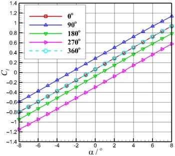
Lift curves of equivalent aerofoil at different phases.

In Fig. 8, one lift curve reflects the lift characteristics of the equivalent aerofoil at a phase angle. For the same angle-of-attack, taking the force coefficients of different lift curves, the lift characteristics of the aerofoil in a motion cycle can be obtained. It can be seen that the lift curve of the equivalent aerofoil is similar to the ordinary aerofoil, which keeps linear at small angles of attack.
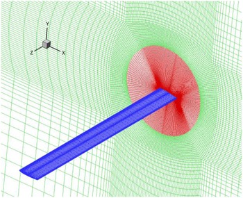
For 3D CFD calculation of the wing, the calculation adopts a half-model considering the symmetry and the mesh is showed in Fig. 9. The length of the X and Y directions of the computational domain is consistent with 2D calculation, and the length of the Z direction is
 $160c$
. The computational domain is also divided into two zones. The inner zone is a cylindrical zone with a mesh of 1.9 million, which can rotate with the wing; the outer zone is a stationary zone with a mesh of 2.6 million and a total mesh for 3D calculation is 4.5 million.
3D mesh of NACA 0012 straight wing.

Symmetry boundary condition is used for the planes of symmetry in the inner and outer zones, and the other settings are consistent with the 2D CFD calculation. The sliding mesh method is used to calculate the pitching motion again.
3.1.2 Comparisons of different methods
The reduction frequencies are
 $k = 0.1$
, 0.3 and 1.0, respectively. For pitching motion of
 ${\alpha _0}{\rm{ = }}{{\rm{4}}^{\rm{o}}}$
and
 ${\alpha _m}{\rm{ = }}{{\rm{4}}^{\rm{o}}}$
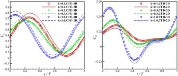
, the lift and drag coefficients obtained by 2D and 3D CFD methods are compared as follows:
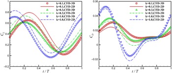
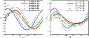
Comparisons of 2D and 3D CFD results for NACA 0012 wing with AR = 20.

In Fig. 10, it can be seen that there exists difference between the aerodynamic curves of the aerofoil and the wing, which comes from the three-dimensional effect. With the increase of reduction frequency, the effect of additional mass is enhanced, and the phase of aerodynamic curve is advanced [Reference Yu and Bernal33] for both 2D and 3D.
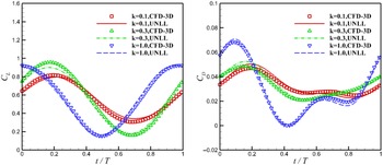
The improved method can be called UNLL (unsteady lifting-line). Firstly, the influence of the number of horseshoe vortices on the solution of UNLL is studied. The wing is divided into 10, 30, 50 and 80 elements, respectively. For
 $k = 0.3$
, the lift and drag coefficients calculated by UNLL with different number of horseshoe vortices are compared as follows:
Comparisons of UNLL results with different number of horseshoe vortices.

It can be seen in Fig. 11 that for N = 10, the lift coefficient calculated by UNLL has some differences with the other three curves. However, for N > 30, UNLL results are basically not affected by the number of horseshoe vortices. Thus, 50 horseshoe vortices along the spanwise is sufficient for UNLL in this paper.
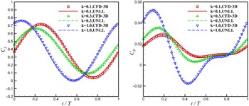
The comparisons between UNLL and 3D CFD results are as follows:
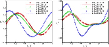
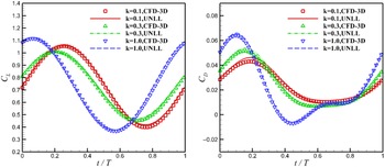
Comparisons of UNLL and 3D CFD results for NACA 0012 wing with AR = 20.

In Fig. 12, the aerodynamic curves calculated by UNLL are in better agreement with 3D CFD results compared with 2D CFD results at every reduced frequency. Thus, the improved method can capture the three-dimensional effect and can be used for the calculation of unsteady aerodynamic force of wings with large aspect ratio.
3.1.3 Comparisons of time cost
For the pitching motion of
 ${\alpha _0}{\rm{ = }}{{\rm{4}}^{\rm{o}}}$
and
 ${\alpha _m}{\rm{ = }}{{\rm{4}}^{\rm{o}}}$
, 2D CFD results with the mean angle-of-attack −2° to 5° are needed in the lifting-line method. The angle interval is taken as
 ${1^{\rm{o}}}$
, and a total of eight 2D cases should be calculated.
The time cost of UNLL and 3D CFD

The comparisons of time cost between UNLL and 3D unsteady CFD calculation are reported in Table 1.
In Table 1, we can be seen that the time cost on the improved method is mainly in 2D URANS simulations, and the cost of the lifting-line is small. Compared with 3D unsteady CFD simulation, the computational efficiency for unsteady aerodynamic simulation is significantly improved at least 12 times by the improved method. Thus, the improved method is suitable for the preliminary design in engineering.
3.2 Pitching motion for wing with medium aspect ratio
Because the improved method is based on the lifting-line method, it’s convenient to predict the aerodynamic force of 3D wings under different aspect ratio. Based on the same 2D URANS data, NACA 0012 wings with aspect ratio AR = 10 and AR = 5 are selected for pitching calculations again.
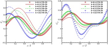
Comparisons of 2D and 3D CFD results for NACA 0012 wing with AR = 10.

Comparisons of 2D and 3D CFD results for NACA 0012 wing with AR = 5.

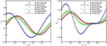
Comparisons of UNLL and 3D CFD results for NACA 0012 wing with AR = 10.

Comparisons of UNLL and 3D CFD results for NACA 0012 wing with AR = 5.

The reduction frequencies are
 $k = 0.1$
, 0.3 and 1.0, respectively. For
 ${\alpha _0}{\rm{ = }}{{\rm{4}}^{\rm{o}}}$
and
 ${\alpha _m}{\rm{ = }}{{\rm{4}}^{\rm{o}}}$
, the calculation results of different methods are compared as follows:
From Figs 13 and 14, it can be seen that the lift curve of 2D aerorfoil is always above the lift curve of 3D wing, but the drag curve is just the opposite. As the aspect ratio decreases, the difference between 2D and 3D becomes larger, indicating that the downwash of the wake is enhanced, and the 3-D effect becomes more and more obvious.
From Figs 15 and 16, the lift curve obtained by the improved method is in good agreement with 3D CFD under different aspect ratio. For the drag curve, although the error at the peak has increased, the drag obtained by the improved method is more consistent with 3D results throughout the cycle compared with 2D CFD. Therefore, the improved lifting-line method in this paper is also suitable for the estimation of unsteady aerodynamic forces of wings with medium aspect ratio.
3.3 Pitching motion for NACA 4412 wing
In order to verify the applicability of the improved method to different type of wings, the NACA4412 wing was selected to perform unsteady CFD calculations, and then the results were compared with the improved method as well.
The CFD calculation method remained the same as the previous section. Firstly, 2D CFD pitching calculations were carried out to obtain aerodynamic data of equivalent aerofoils. Then, NACA4412 wing with AR = 20 was selected for the verification of the improved method.
The reduction frequencies are
 $k = 0.1$
, 0.3 and 1.0, respectively. For
 ${\alpha _0}{\rm{ = }}{{\rm{4}}^{\rm{o}}}$
and
 ${\alpha _m}{\rm{ = }}{{\rm{4}}^{\rm{o}}}$
, the calculation results of different methods are compared as follows:
Comparisons of 2D and 3D CFD results for NACA 4412 wing with AR = 20.

In Fig. 17, there is still an obvious difference between 2D and 3D results. However, the aerodynamic curves obtained by the improved method in Fig. 18 are in good agreement with the 3D CFD results, indicating that the proposed method is also effective for the wing with camber.
Comparisons of UNLL and 3D CFD results for NACA 4412 wing with AR = 20.

From another point of view, the improved method can also be regarded as a reduced order model. Based on the idea of lifting-line, the mapping relationship between 2D and 3D is constructed, and low-dimensional aerodynamic data is used to predict high-dimensional aerodynamic forces, achieving the purpose of time-saving for unsteady calculations.
3.4 Pitching motion for tandem configuration
The above calculations are all about the single wing, but in engineering, there are often multiple wing aerodynamic problems, such as biplane wing and tandem wing [Reference Hosseini, Tadjfar and Abba34]. For 3D multiple wings CFD calculations, the time cost on mesh generation and computation will also increase, so it is necessary to develop a fast estimation method for these problems. Thus, the tandem configuration is selected in order to verify the effectiveness of the improved method in calculating unsteady aerodynamic forces of multiple wings.
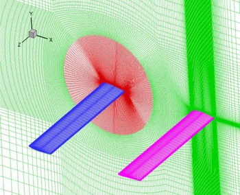
The tandem shows in Fig. 19. The front wing adopts NACA 0012 aerofoil with a geometric installation angle of 4°, and the rear wing adopts NACA 4412 aerofoil with a geometric installation angle of 0°, and the front and rear wing chords are both 1.0 m. In this case, the front wing will perform the pitching motion while the rear wing keep stationary. The pitching centre of the front wing is around its own 0.25c position and the distance between the front and rear wings is D = 4 m. The span of front and rear wing is 10 m, corresponding to AR = 10. 3D mesh is showed in Fig. 20.
Schematic of tandem wing.

3D mesh of tandem wing.

In the previous sections, we expands the concept of aerofoil and considers that every phase of the pitching motion corresponds to an aerofoil. Furthermore, multiple aerofoil can also be considered as a single equivalent aerorfoil, and we can use 2D CFD results of multiple aerofoils to calculate the unsteady aerodynamic force of 3D multiple wings. In other words, the multiple wings can be considered as a single equivalent wing, which avoids modeling each wing separately and can further improve the calculation efficiency for complex configuration.
Figure 21 shows the equivalent aerofoil for the tandem. For each phase, the aerodynamic force of the equivalent aerofoil is defined as the sum of the front and rear aerofoils, and the aerodynamic force of the equivalent wing is the sum of the front and rear wings. By changing the direction of the free stream flow, the 2D aerodynamic force of the equivalent aerofoil at different angles of attack can be obtained. Then, the aerodynamic force of 3D equivalent wing is calculated based on the improved method. The reference chord length and reference area of the equivalent wing are defined as the chord length and area of a single wing.
Equivalent aerofoil for tandem configuration.

The CFD calculation method remains the same as the previous section. The front wing performs periodic pitching movement with
 ${\alpha _m}{\rm{ = }}{{\rm{4}}^{\rm{o}}}$
, while the rear wing remains stationary. The reduction frequencies are
 $k = 0.1$
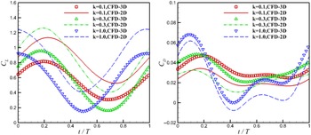
, 0.3 and 1.0. For 0º angle-of-attack, the total aerodynamic force of the tandem configuration calculated by different methods is compared as follows:
In Fig. 22, it still can be seen obvious difference between 2D and 3D aerodynamic curves of the tandem configuration. However, the aerodynamic curves obtained by the improved method in Fig. 23 are in good agreement with 3D CFD results, indicating that the improved method can also be used to estimate the overall unsteady aerodynamic force of 3D multiple wing configuration.
Comparisons of 2D and 3D CFD results for tandem wing.

Comparisons of UNLL and 3D CFD results for tandem wing.

4.0 Conclusions
In this paper, the
 $\Gamma - based$
lifting-line method is improved and extended to the unsteady calculation. Compared with the original lifting-line method, the improved method uses the aerodynamic data obtained by 2D URANS as the input, and combines unsteady K-J theorem to calculate the aerodynamic force of 3D configuration.
Using the improved method, this paper calculates the pitching motion of 3D wing at different aspect ratio and reduction frequencies, and compares the results of UNLL with the 3D CFD simulations. In all verification examples, the improved method is in good agreement with the 3D CFD results, which shows the effectiveness of the simplified method. Compared with 3D unsteady CFD simulations, the computation efficiency of the simplified method is improved by more than 12 times. In addition, the improved method can also be used for the estimation of unsteady aerodynamic force of multiple wing configuration.
It should be noted that the augmented lifting-line method in this paper simplifies the wake calculation. Thus, the appropriate application condition for this method is the calculation of the longitudinal motion of the wing at medium- and low-reduction frequencies. For very-high-reduction frequencies, especially when flow separation occurs, the mutual interference of the wing wake becomes complicated, and the unsteady and 3D effects are more pronounced. In these states, non-local effects are dominant, and the simplified treatment of the wake in this paper may be invalid.
It can be seen that the calculation time of the improved method is mainly spent on 2D CFD calculations. In order to reduce the cost of 2D CFD calculations, the method in this paper can also be combined with some data-driven 2D aerodynamic reduced-order models [Reference Li, Kou and Zhang35], which can further decrease the computation expense for 3D unsteady problems.
Acknowledgements
The author acknowledges support from Natural Science Basic Research Program of Shaanxi (Program NO. 2022JQ-060) and Shaanxi Provincial Key Research and Development Program (Program NO. 2021ZDLGY09-08), so that the author can successfully complete this study.