Introduction
The reflectarray antennas are new generation of the planar array antennas, which can be designed in both active and passive forms. The active electromagnetic band-gap (EBG) based reflectarray antennas can be tuned and steer the antenna beam without any mechanical movement of the antenna [Reference Johnson, Brunton, Kutz and Kundtz1]. In the reflectarray antenna, the beam steering is done similar to the phased array antenna. However, the complexity, power consumption, and the cost of the reflectarray antenna are much lower than the phased-array antenna [Reference Lim, Caloz and Itoh2, Reference Hum, Okoniewski and Davies3]. Nowadays, due to features such as flatness, slimness, low weight, low power consumption, and electronically beam steering, EBG-based reflectarray antennas are used in aerospace, maritime, navigation, ground station applications, and so on [Reference Zhou, Jong and Lo4]. Using reflectarray antennas with active EBG, airplanes provide data services such as live TV, Internet, live video communication, and so on [Reference Chou, Lin and Wu5]. Some of the previous reflectarray antennas support only linear polarization [Reference Sievenpiper, Schaffner, Song, Loo and Tangonan6]. These types of antennas are not suitable for many applications. In satellite communications due to Faraday's effect and rotation of the electric field, the polarization of electromagnetic wave changes and the polarization loss occurs. In order to reduce the loss, circular polarized antenna is suggested [Reference Guo, Zhang, Li and Hong7]. It is also demanded in many applications that the circular polarized antenna has the ability of creating both right- and left-handed circular polarizations (RHCP and LHCP). For instance, if the RHCP antenna gain in desired direction is low, usually the LHCP antenna gain is high. Antenna with two polarizations also enhances the channel capacity [Reference Dong, Choo, Heath and Ling8]. The circular polarized EBG are introduced in [Reference Mener, Gillard, Sauleau, Cheymol and Potier9, Reference Liang, Sanz-Izquierdo, Parker and Batchelor10], which cannot steer the antenna beam. A reflectarray antenna with limited steering angle is proposed in [Reference Li and Abbosh11]. In this paper, a reflectarray antenna with capabilities of electronically beam steerable up to ±40o is designed. The beam steering property in this type of antenna is achieved based on a flat tunable surface that acts as an EBG reflector. The EBG structure is equipped with active varactor diodes whereas an active electronic board controls the biasing voltages of the varactors. Therefore, when the biasing voltage changes and the phase of the reflected wave varies, the direction of the reflected beam will lie towards the desired direction. The designed reflectarray antenna is also equipped with both RHCP and LHCP, and capability of switching electronically between them.
Design of circular polarized antenna element
In the EBG reflectarray antennas, the polarization of the reflected wave from the reflector depends on the polarizations of the antenna element and the radiated wave from the antenna feed. As it is shown in Fig. 1, in the element design of the reflectarray antenna with circular polarization, the idea of designing circular polarized element in a passive reflectarray antenna is utilized [Reference Chang and Huang12].
A passive circular polarized antenna element via two stubs [Reference Chang and Huang12].

In Fig. 1, L x and $L_y$ are the length of stubs. According to equation (1), it is assumed that the electric field of the incident wave in the direction of −Z is LHCP:

Then, equation (2) is used to express the reflected electric field [Reference Liang, Sanz-Izquierdo, Parker and Batchelor10, Reference Yang and Rahmat Samii13].

If L x = L y, the relation (2) may be rewritten as follows:

where E 1 is constant. Equation (3) shows that the polarization of the reflected wave is RHCP in the + Z direction. Similarly, in the case of L x = L y, if the polarization of the incident wave is RHCP, the polarization of the reflected wave will be LHCP [Reference Yang and Rahmat Samii13, Reference Malfajani and Atlasbaf14]. In the passive reflectarray antenna element in Fig. 1, the phase of reflected wave is compensated by the variations of the length of stubs L x and $L_y$ . Similar to the element introduced in Fig. 1, in [Reference Malfajani and Atlasbaf14], a broadband circular polarized passive reflectarray antenna element is presented which is shown in Fig. 2.
A circular polarized reflectarray antenna element [Reference Malfajani and Atlasbaf14].

Based on the introduced elements in Figs 1 and 2, a new reflectarray antenna element is proposed where the corresponding phase compensation is done by varying the capacitor of the varactor instead of varying the stub length.
Design of element for the reflectarray antenna
In the design process of a passive reflectarray antenna element, the physical parameters of the proposed unit cell are changed to spread the range of phase variation of the cell in a wide frequency band and increase the antenna bandwidth. However, in the reflectarray antenna element, the variations in the varactor capacitor cannot change widely the unit cell phase response, so the antenna bandwidth is low and other methods should be utilized to increase the antenna bandwidth. Figure 3 shows the proposed antenna element for the reflectarray antenna. The element is based on EBG structure composed of a circular patch, ring, via, and two varactor diodes which are connected between the inner patch and outer ring [Reference Fazaelifar, Jam and Basiri15]. The via connects the inner patch to the ground for biasing the varactors.
The proposed reflectarray antenna element. (a) Front view, (b) side view.

The physical parameters of the unit cell and the capacitance of the varactors should be determined properly to increase the bandwidth of the antenna and create circular polarization.
Determination of the dimensions of the proposed element
In this section, the initial dimensions of the physical parameters of the element are calculated in the frequency band of 10.5–12 GHz. The RT5880 with dielectric constant ɛr = 2.2, the thickness of h sub = 0.787 mm, and loss tangent 0.0009 is used as the substrate of the reflector plane. The mushroom like EBG structure is modeled by an LC parallel circuit. The initial dimensions of the antenna elements can be estimated from equations (4–6) [Reference Sievenpiper, Schaffner, Song, Loo and Tangonan6]:


In the above equations, L, C, and ω 0 are the inductance, capacitance, and resonance frequency of the element. W is the total diameter of the element, G is the air gap between the two elements, and P is the period of the mushroom like EBG structure. In order to reduce the mutual coupling between adjacent elements and prevent the creation of the grating lobes in the radiation pattern, the period of the reflectarray antenna elements is selected to P = 0.55λ 0. Using equations (4–6), the initial dimensions of the antenna elements are calculated for the maximum frequency of the desired band. It should be mentioned that increasing the varactor capacitor leads to decreasing the resonant frequency of the structure. The initial values of the physical parameters of the unit cell at f 0 = 12 GHz are tabulated in Table 1.
Initial dimensions of the antenna unit cell.

As shown in Fig. 3, there are too many parameters for the antenna element that should be determined. At frequency f 0 = 12 GHz, the values of some of parameters such as the surrounding rings (L 1, L 2) and the air gaps (S 1, S 2, S sep) are very small. So, the initial values of all these parameters are assumed to be fixed as follows:

Other physical parameters of Fig. 3 may be expressed in terms of the fixed parameters of equation (7):

The part number of the utilized varactor diode is SMV2020 with an average width of 0.5mm. So, W 1 = W 2 = 0.5 mm is assumed in Fig. 3. Using the results of Table 1 and equations (7) and (8), the initial dimensions of the reflectarray antenna element at the frequency of f 0 = 12 GHz are calculated and presented in Table 2.
Initial dimensions of the reflectarray antenna element.

Unit cell analysis and simulation
In Fig. 4(a), the Floquet analysis in CST full wave electromagnetic simulator is utilized for simulation of the unit cell. The phase response for normal incidence of the proposed element is obtained and optimized using the PSO algorithm. The aim of the optimization is creation of adjacent resonant frequencies in the frequency band of 10.5–12 GHz. Table 3 presents the optimized dimensions of the unit cell.
The normal incidence phase response. (a) Floquet analysis, (b) phase response of the unit cell at f = 11.4 GHz.

Optimized dimensions of the proposed element.

The phase response of the optimized unit cell in terms of the variations of the varactor capacitor from 0.17 to 1.7 PF for normal incidence and in desired frequency f = 11.4 GHz is determined and plotted in Fig. 4(b).
To form a reflectarray antenna, the elements must be able to create at least a phase difference of 360° in the desired frequency [Reference Malfajani and Abbasi Arand16]. According to Fig. 4, the phase difference at f = 11.4 GHz is about 360°. Obviously, phase difference less than 360° will reduce the antenna performance.
Fabrication and test of the antenna unit cell
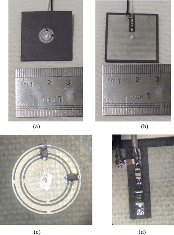
One of the best simple known methods which can be used to check the validity of a designed reflectarray unit cell is waveguide simulator technique [Reference Elshennawy and Attiya17]. Based on the optimized dimensions of the proposed unit cell in Table 3, the antenna element was fabricated. Figures 5(a) and 5(b) illustrate the front and back views of the fabricated unit cell. In Fig. 5(c), the varactor diodes on the cell can be seen quite clearly under a microscope. The magnified biasing circuit under the microscope is also shown in Fig. 5(d). To prevent unwanted interference, the element is biased via LC low pass filter (L = 12 nH, C = 10 nF) and a 1 kΩ series resistor mounted on the back of the unit cell.
The fabricated unit cell. (a) Front view, (b) back view, (c) magnified front view, (d) magnified back view.

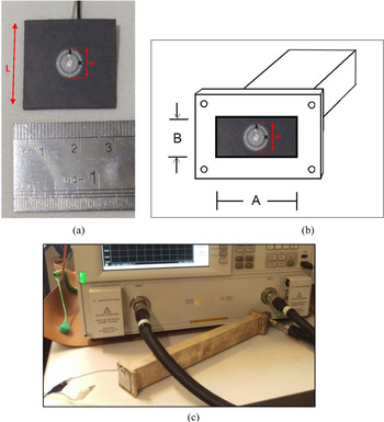
For experimental validation of the antenna element, it's fixed in the aperture of a waveguide. Due to the size of the antenna element, the waveguide WR102 is implemented for the measurement. As shown in Fig. 6, the dimensions of the fabricated unitcell are W = 8.33 mm and L = 30 mm. The aperture size of the WR102 is A = 25.90 mm, B = 12.95 mm. Therefore, the fabricated unitcell will cover all the aperture of the waveguide. The waveguide port is connected to the Agilent PNA Network Analyzer E8363 via waveguide-SMA adaptor. The phase of the reflected wave of the fabricated element in terms of the biasing voltage in desired frequency of 11.4 GHz is measured and tabulated in Table 4.
Waveguide port simulation. (a) Dimension of the fabricated unitcell, (b) the aperture size of WR102, (c) measurement setup.

Measured phase response of the fabricated unit cell in terms of the biasing voltage.

To compare the simulation and measurement results, two key points should be considered. First, the simulated phase response is in terms of varactor capacitance, while the measured one is in terms of its biasing voltage. Therefore, in order to compare the simulated and measured results, the voltage of the varactor is converted to its corresponding capacitance using equation (9).

where the varactor parameters are listed in Table 5.
The varactor diode parameters.

Moreover, since the polarization of the incident wave in the waveguide simulator is liner, both the simulated and measured phase responses of the unit cell should be considered in linear polarization. Based on the information of Table 4, the simulated and measured phase responses of the antenna element are plotted in Fig. 7. The comparison results verify good coincidence between simulation and measurement results.
Measured and simulated phase response of the unit cell at f = 11.4 GHz.

Beam steering in reflectarray antenna
In this section, a steerable reflectarray antenna is proposed based on the optimized unit cell in section “Design of circular polarized antenna element”. Therefore, it is necessary to identify the incident and reflected waves vectors and the position vector of each element in the reflector plane. In Fig. 8, the surface of the reflector is divided into four areas. Because of symmetry consideration, the phase of each element in one quadrature is calculated and the same process will be used for obtaining the required phases of elements in other areas.
Layout of a reflectarray antenna. (a) The incident and reflected wave vectors, (b) position of the feed and the antenna elements.

Assuming the center feed reflectarray antenna, the required phase of ith element can be determined from equation (10) [Reference Huang and Encinar18]:

where (x i, y i) is the position of ith element, d i is the distance from the center of the feed antenna to ith element, and k o is the propagation constant in air. (θ in, ϕ in) and (θ ref, ϕ ref) are the directions of the incident and reflected waves, respectively.
In order to arrange the antenna elements in the reflector plane, the required phase for each element is calculated using the code provided in MATLAB software. As shown in Fig. 8(b), the reflector is divided into four distinct areas. This code receives the direction of the required reflected beam $\lpar \theta _{ref}\comma \;\phi _{ref}\rpar$ in area1 as the input parameter, and the phases of elements of the reflectarray antenna in this area are calculated based on equation (10). The phase of other elements in areas 2, 3, and 4 are calculated from the following transformation equations:

The required phase of each element must be supplied through the varactor capacitor. Therefore, the phase response of the unit cell versus the varactor capacitor in Fig. 4 is utilized to calculate the capacitance of each element. Using MATLAB software, at first, the unit cell phase response is estimated by a polynomial function. This function is used to calculate the capacitors of the varactors, which are saved in a matrix form. The capacitance of a varactor depends on its biasing voltage. The capacitance diagram of the varactor in terms of biasing voltage is given in corresponding data sheet. This diagram is estimated by a polynomial function and the biasing voltages of varactors are obtained using the capacitors.
Feed of the reflectarray antenna
The polarization of a reflected wave from an EBG reflectarray depends on the polarizations of the reflectarray antenna elements and the polarization of the incident wave. Therefore, as it is mentioned in section “Design of circular polarized antenna element”, in order to have a circular polarized reflectarray antenna, the polarization of the radiated wave from the antenna feed must be circular as well as the antenna elements. To this end, an ortho-mode transducer (OMT) polarizer is considered as a feed for the reflectarray antenna. The feed has two RF ports R and L, which can produce RHCP and LHCP. When the RF signal reaches the port R/L, RHCP/LHCP EM wave will be appeared on its aperture, respectively [Reference Leal-Sevillano, Cooper, Ruiz-Cruz, Montejo-Garai and Rebollar19, Reference Esteban and Rebollar20]. The OMT polarizer as the feed of the reflectarray antenna was designed and fabricated [Reference Esteban and Rebollar20]. The schematic views of the simulated and fabricated OMT polarizer antenna are depicted in Fig. 9.
The OMT polarizer antenna [Reference Esteban and Rebollar20]. (a) Simulated, (b) fabricated.

The reflection coefficient and the radiation pattern of the simulated and fabricated polarizer antenna are shown in Fig. 9. According to Fig. 10, the designed antenna has S 11 ≤ −10 dB over the frequency band from 9.5z to 12.5 GHz. The gain of antenna is also about 8.5 dBi at f = 11.4 GHz. The polarization of the antenna is circular in the desired frequency range whereas the axial ratio less than 1.5 dB is achieved [Reference Fazaelifar, Jam, Basiri and Azadi21].
The simulated and measured diagrams of the polarizer antenna [Reference Fazaelifar, Jam, Basiri and Azadi21]. (a) S 11, (b) radiation pattern at f = 11.4 GHz.

The type of polarization (RHCP or LHCP) of the designed reflectarray antenna is changed electronically by varying the status of an RF switch between ports R and L. The switch is controlled by a signal, which comes from the active board. The connection of the RF switch to the feed antenna will be explained in the active board section. The illumination of the radiation pattern of feed plays an important role for determining of the focal length and consequently, the efficiency of the reflectarray antenna. The shape of the pattern is estimated by cosq(θ 0). So, the radiation pattern of the feed in linear scaling is compared with cosq(θ 0) for different values of q. In this work, q = 4.5 is selected for the antenna feed at the frequency of 11.4 GHz.
Optimum focal length of the reflectarray antenna
The feed antenna should be placed in a proper position where the antenna efficiency reaches to its maximum level. The spillover and illumination taper efficiencies have the greatest effect on the total efficiency of the reflectarray antenna. Therefore, the antenna total efficiency can be estimated by equation (12), [Reference Maddahali and Forooraghi22, Reference Shaker, Chaharmir and Ethier23]:

where, q is exponent of the feed pattern in Cos q(θ 0) and ϕ RA/2 is subtended angle between the center of the feed and the reflectarray aperture (Fig. 8(b)). Using MATLAB software and in aid of equation (12), the total efficiency of the reflectarray antenna for q = 4.5 at ϕ RA/2 = 48° will be maximum. Determining subtended angle ϕ RA/2 and using equation (12), the focal length F and F/D of the reflectarray antenna are calculated and summarized in Table 6.

where, D is diameter of the reflectarray antenna aperture (Fig. 8(b)), N is the number of elements of a row or column, and P is the period of the antenna elements.
The reflectarray antenna parameters.

Active board of the reflectarray antenna
One of the necessary parts of a reflectarray antenna is an electronic board, which provide the analog voltages for biasing of the varactors, controlling and displaying the polarization status of the antenna. The main sections of the board, including digital-to-analog converter (DAC), RF switch, and control board are shown in Fig. 11.
Fabricated electronic active board of the reflectarray antenna.

Digital-to-analog converter
The chip AD5370 is a DAC from ANALOG DEVICES company, which is used to produce the required analog voltages for biasing the varactors. The resolution of the DAC is 16 bits and it has 40 analog channels. The AD5370 chipset is connected to a computer through a USB port to setup the chipset registers. Using a program in MATLAB software and considering the AD5370 datasheet, the relationships between DAC output voltages and the values of registers are determined. Then, the program gives the values of the chipset registers to achieve the required analog voltages on desired DAC channels. For example, if it is necessary to produce analog voltages 5 and 9.2358 V on channels 39 and 32, these voltages are given to the MATLAB program and the output of the program will determine the values of the registers (X,M,C,Offset) in hexadecimal as follows:

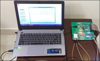
As it is shown in Fig. 12, loading the above values into the AD5370 registers through a USB port interface creates the voltages 5.0 and 9.2358 V on channels 39 and 32, respectively. In the same way, all required analog voltages for biasing of the varactors are provided on DAC channels.
Loading the values into the electronic board through the USB port.

RF switch
To change the polarization status of the reflectarray antenna, the switch CCR-33 from TELEDYNE Company is used. According to Fig. 11, the switch has three RF ports, which are compatible with the SMA connectors. The insertion loss of this switch is less than 0.5 dB and the isolation between the ports is greater than 60 dB in the frequency range from DC to 18 GHz. The ports 1 and 2 of the RF switch are connected to RHCP and LHCP ports of the septum feed antenna, respectively. Consequently, when the switch is off/on, the polarization status in port 3 will be RHCP/LHCP. The status of the switch CCR-33 is changed by applying a voltage control of 5 V to its logic terminal that is called Logic1. This voltage is supplied from control board.
Control board
The control board of the reflectarray antenna is presented in Fig. 8, which is utilized to provide the control voltages and display the corresponding status. To change the polarization status of the reflectarray antenna, the appropriate voltage is applied to RF switch from the control board. The control board also provides the power distribution to the supplies of the RF switch and DAC board.
Simulation of the reflectarray antenna
In this section, a reflectarray antenna, which is composed of an 16 × 16 array of the proposed elements is designed and simulated. These elements are arranged in the four areas of the reflector plane based on the capacitors that are determined in Section “Beam steering in reflectarray antenna” to form the reflectarray. The OMT polarizer feed is placed on the focal point F = 94.6 mm and the ports R and L of the feed are connected to the corresponding ports of RF switch, which is shown in Fig. 12. Finally, the designed reflectarray antenna is simulated using the full-wave CST electromagnetic software. It should be noted that the simulation of active element, such as varactor diode, are not included in CST full wave simulator. Therefore, the equivalent Spice circuit model (Fig. 13) is utilized in CST simulations. Figures 14(a) and 14(b) illustrate the schematic view of the designed reflectarray antenna, where R S and C v can be determined from equation (9) and Table 5.
Equivalent circuit of the varactor diode.

The designed 16 × 16 reflectarray antenna. (a) Front view, (b) back view, (c) magnified view of biasing network.

The designed reflectarray antenna is composed of the feed antenna, electronic board, biasing tracks, and reflector plane. Each element is biased via LC low pass filters and 1 kΩ series resistor that are connected to biasing tracks. As demonstrated in Fig. 14(c), in order to reduce the effects of RF signals on biasing network, the tracks are placed behind the reflector plane. The feed and the electronic board are designed, fabricated, and tested. However, in the desired frequency band, the elements are so small that the process of inserting vias and assembling the varactor diodes is very costly. Therefore, in order to ensure the antenna performance, the proposed reflectarray antenna is simulated for various steering angles and for both RHCP and LHCP polarizations.
The reflectarray antenna is programed to steer the beam in θ ref = 3° and ϕ ref = 0° direction in both LHCP and RHCP modes at frequency f = 11.4 GHz. As it is mentioned in subsection “RF switch”, when the switch is off, RHCP EM wave is radiated from the antenna feed and the reflectarray antenna will propagate LHCP EM waves. The LHCP radiation pattern of the deigned reflectarray antenna is depicted in Fig. 15.
The radiation pattern of reflectarray antenna in LHCP mode.

Similarly, when the switch is on, the reflectarray antenna will propagate RHCP EM waves. The RHCP radiation pattern of the reflectarray antenna is demonstrated in Fig. 16.
The radiation pattern of reflectarray antenna in RHCP mode.

The results of Fig. 17 confirm that the acceptable values of the axial ratios (AR = 0.89 dB and AR = 0.96 dB) are achieved in the desired direction, which guarantee the high quality of circular polarization. Comparison of Figs 15–17, for the two LHCP and RHCP shows that, the results are not significantly different.
The axial ratio of the reflectarray antenna. (a) LHCP axial ratio, (b) RHCP axial ratio.

In Fig. 18, the LHCP 2D radiation patterns of the designed reflectarray antenna (based on Table 5), for steering the antenna beam towards different values of θ ref and in desired frequency f = 11.4 GHz are illustrated. It should be mentioned that ϕ ref = 0° is considered in all of the simulations.
The LHCP 2D radiation patterns of the antenna at steering angle of $\phi _{ref} = 0^0$ . (a)θ ref = 3°, (b)θ ref = 16°, (c)θ ref = 30°, (d)θ ref = 33°, (e)θ ref = 40°, (f)θ ref = 45°.

Based on the simulation results of Fig. 18, it is seen that the side lobe level (SLL) of the designed reflectarray antenna has deteriorated when the beam steering angle in θ direction increases up to 45°. This phenomenon may be explained as follows. The increase of the angle θ causes the deviation of the phase response curve from linear shape. Depending on the acceptable SLL and required gain, the maximum steering angle of the reflectarray antenna can be determined. According to equations (10) and (11), the beam of the designed reflectarray antenna can steer in any ϕ and θ directions. In order to show the beam steering of the antenna in all directions, the 2D and 3D views of radiation patterns are illustrated in Fig. 19 in (θ ref = 16°, ϕ ref = 15°) and (θ ref = 16°, ϕ ref = 45°) directions.
The 2D and 3D side and top views of the radiation patterns (a, b)2D and 3D θ ref = 16°, ϕ ref = 15°, (c, d) 2D and 3D θ ref = 16°, ϕ ref = 45°.

Comparing the simulation results of Figs 18 and 19, confirms that increasing the steering angle in ϕ direction does not increase the SLL as much as steering angle in θ direction. In the same manner, the beam of the designed reflectarray antenna can steer in $-\theta _{ref}$ direction. Generally, the simulation results of Figs 18 and 19 are summarized in Table 7 for different values of both θ ref and $\phi _{ref}$
 directions.
The simulation results of the active reflectarray antenna at f = 11.4 GHz.

Note that the DAC board in subsection “digital-to-analog converter” supports 40 analog channels. In practice, for biasing the 16 × 16 reflectarray antenna independently, seven DACs are needed.Note that the fabricated active board has been used as a proof of concept to validate its operation.
Conclusion
In this paper, a single layer circular polarized tunable reflector is designed based on the EBG unit cell and varactor diodes. For the proposed reflectarray antenna, an electronic active board is designed and fabricated to provide all of required control signals. An OMT polarizer is also utilized as the feed antenna. This feed is placed in a proper distance with respect to EBG reflector to create a circular polarized reflectarray antenna. The effects of beam steering on the antenna gain in both θ and ϕ directions are studied. The simulated radiation patterns of the designed reflectarray antenna confirm that the proposed antenna is electronically beam steerable up to θ ref = ±40°. The antenna also has the capability of switching electronically between the RHCP and LHCP. Having two special features of the 3D beam steering and interchangeable circular polarizations has made the reflectarray antenna distinctive for many applications.
 Mohammad Fazaelifar received a B.Sc. degree in Electronics from the University of Guilan in 2000 and received his M.Sc. degree in Communication Engineering from Shiraz University, in 2003. He received his Ph.D. from Shiraz University of Technology in 2018, in Communication Engineering. He is a researcher at the Electrical Engineering Department of Shiraz University of Technology. His main research interests are design and fabrication of antennas and Wireless Communication Network.
 Shahrokh Jam received his B.Sc. degree from Shiraz University in 1988 and his M.Sc. and Ph.D. degrees from Iran University of Science and Technology in 1992 and 2001, respectively, all in Electrical Engineering. He was the faculty member of Shiraz University from 1993 to 2004 and then he joined Shiraz University of Technology as associate professor. Now he is a full university professor. His main fields of research are microwave, antenna, microstrip antenna, and high frequency circuits. He is a IEEE senior member.
 Raheleh Basiri received the B.Sc., M.Sc., and Ph.D. degrees in communication engineering from Shiraz University, Shiraz, Iran, in 2005, 2008, and 2015, respectively. Since 2015 she has been with the Electrical Engineering Department, Shiraz University of Technology, where she is now an assistant Professor. Her research interests include numerical methods in electromagnetic theory, microwave circuits, electromagnetic wave interactions with special materials and metamaterials.