1. Introduction
Modern manufacturing industry is trending toward small-batch production, high flexibility, and high intelligence [Reference Ji, Lee, Yoo, Suh, Kwon, Park, Lee and Kim1]. Robotic assembly tasks requiring high performance and customization have appeared in many fields, including aerospace, consumer electronics, and construction industry [Reference Zhang, Wang, Zhao and Ke2–Reference Apolinarska, Pacher, Li, Cote, Pastrana, Gramazio and Kohler4]. High-precision manipulation in dynamic open environment is a comprehensive challenge, including environment prediction, task learning, state monitoring, and so on, which attracts many researchers. Hou et al. [Reference Hou, Li, Hsu, Zhang and Xu5] proposed a fuzzy logic-driven variable time-scale prediction-based reinforcement learning (RL) algorithm for environment prediction and assembly action control, so as to solve the problems of long training time and low data efficiency of the RL algorithm in the complex environment of multiple peg-in-hole assembly. Zachares et al. [Reference Zachares, Lee, Lian and Bohg6] proposed a hierarchical probabilistic method for autonomously assembling parts with uncertain types and positions by learning physical interaction. Lee et al. [Reference Lee, Park, Jang, Kim and Park7] proposed an approach based on Gaussian mixture model to estimate contact state in order to prevent or monitor unexpected situations during peg-in-hole assembly.
In industrial production with a relatively stable environment, the utilization of existing conditions and information directly affects the efficiency and quality of the manipulation. Therefore, how to improve the assembly strategy or the execution device, and how to realize the effective use of the sensing information under different sensing constraints have been hot topics in robotic assembly research for a long time.
For the assembly problem of irregular-shaped parts, Song et al. [Reference Song, Kim and Song8] proposed a force control strategy based on visual geometric feature and CAD models for complex-shaped parts assembly. Liu et al. [Reference Liu, Li and Xing9] proposed a probabilistic control approach that realizes simultaneous precision assembly of multiple irregular-shaped objects. Wu et al. [Reference Wu, Liu and Wang10] summarized a new method for the assembly of circular–rectangular compound on the base of six-dimension force sensor.
In introducing the compliance device, Hamaya et al. [Reference Hamaya, Lee, Tanaka, von Drigalski, Nakashima, Shibata and Ijiri11] equipped the robot with a compliant module on its wrist and presented a novel control framework for exploring assembly strategies based on the softness and environmental constraints. Xing et al. [Reference Xing, Liu, Liu and Xu12] utilized a compliant mechanism with multiple degree of freedoms to realize compliant insertion in precision assembly and proposed an effective assembly strategy accordingly.
Regarding the effective use of the sensing information, Luo and Li [Reference Luo and Li13] considered the contact-rich phase and proposed a learning-based method for high-precision robot assembly. Song et al. [Reference Song, Li, Quan, Yang and Zhao14] put forward a robotic assembly method based on deep Q-learning using visual and force sensing information. In particular, when the sensing accuracy is limited, Drigalski et al. [Reference von Drigalski, Hayashi, Huang, Yonetani, Hamaya, Tanaka and Ijiri15] proposed an efficient in-hand pose estimation method that does not require accurate camera calibration, only using off-the-shelf visual and force sensors on the wrist. Kim et al. [Reference Kim, Choi, Son, Yun and Yoon16] presented a vision-force guided precise assembly system in which the combined system of a force sensor and two charge-coupled device cameras, instead of an expensive three-dimensional (3D) sensor, is used to reduce cost.
The robotic assembly method based on attractive region in environment (ARIE) presents an effective way to solve the high-precision assembly problem under the limitation of sensing accuracy or robot motion accuracy. Qiao et al. [Reference Qiao, Wang, Su, Jia and Li17] found that ARIE, which was reported as Qiao’s concept [Reference Gao, Shi, Fukuda, Li and Huang18], exists in the vast scope of a new space of robotic manipulation. Their series work including cognition, strategy, control, and mechanism in this area provides an important approach for robotic system to realize high-precision manipulation by efficiently leveraging environment information [Reference Chen and Qiao19–Reference Zhong, Chen and Zhou22].
Inspired by the concept of ARIE, Su et al. [Reference Su, Qiao, Liu and Ou23] proposed a sensorless manipulation strategy for the piston-peg-rod assembly where the hole is unfixed. Li et al. [Reference Li, Li, Qiao, Ma and Li24] used the information of the contact force direction to improve the assembly strategy based on ARIE, and the robustness of the system was enhanced. Salem and Karayannidis [Reference Salem and Karayiannidis25] proposed novel strategies for the hole-in-peg and nut-in-screw assemblies based on the combination of quasi-static models and the concept of ARIE, and the experiments showed a high success rate and great performance in error elimination. Park et al. [Reference Park, Park, Lee, Park and Bae26] introduced the concept of ARIE into a compliant peg-in-hole assembly method based on blind searching using a spiral force trajectory, which leads to a significant decrease in the variance of the elapsed time.
The goal of this paper is to try to solve the possible blocking problem in the assembly process caused by the nonconvex structure of parts at the strategic level. Based on the theory framework of ARIE, a new assembly strategy for nonconvex axisymmetric components is proposed. The main contributions of this paper are as follows:
The geometric characteristics of the assembly constraint region of a class of nonconvex axisymmetric parts are analyzed, and the reasons for assembly failure using the ARIE-based classic strategy are analyzed;
Based on the concept of ARIE, a multi-step sliding strategy is proposed by using the geometric features of the assembly constraint region of the nonconvex axisymmetric parts;
The effectiveness of the proposed multi-step sliding strategy is verified by comparison experiments.
We note that a conference version of this paper [Reference Liu, Chen, Zhang and Gao27] studied the assembly of a pair of nonconvex cylindrical parts. The strategy in the initial article is only for one case, without considering its generalization or comparison. Compared with the previous conference version, in this manuscript, the object of study is a class of axisymmetric parts rather than a pair of specific quasi-cylindrical parts. The influence of axial orientation error of the peg on constraint regions is taken into consideration, and the scope of application of the multi-step sliding strategy is expanded. An explanation of the rationale for the mathematical model of two-point contact in the axisymmetric parts assembly is presented. In addition, comparison experiments are added to illustrate the effectiveness of the proposed strategy in solving the blocking problem caused by nonconvex structures.
2. Problem statement
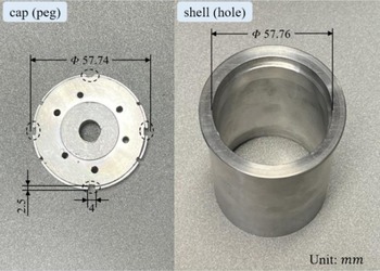
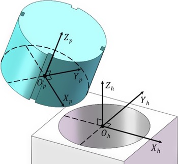
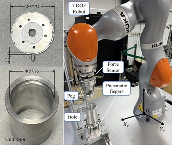
In the precision manufacturing, many peg parts, e.g. end caps, are designed as nonconvex structures to meet the requirements of wiring. The assembly test pieces used for manufacturing a precision instrument include a cap (peg) and a shell (hole), as shown in Fig. 1. The hole is with a circular outline, while the cross-sectional shape of the corresponding peg is an incomplete circle. The grooves on the side of the peg are axisymmetrically distributed and relatively small in volume. Except for the groove area, the clearance is 0.02 mm.
The assembly test pieces used for manufacturing a precision instrument.

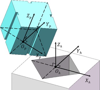
Based on the characteristics of the parts, we propose an assembly model for nonconvex axisymmetric components. The cross-sectional shape of hole is X–Y axisymmetric convex polygon, and the vertexes are located on the symmetry axis. The shape of the cross-section of peg is an axisymmetric nonconvex polygon, and its formation process can be seen as cutting off the edge of the reference pattern matching the hole to generate a limited number of side grooves. The area occupied by the grooves accounts for a small proportion of the total cross-sectional area (e.g., less than 2%). The clearance is extremely small except for the groove area.
Taking the quadrilateral hole and its corresponding peg as an example, Cartesian frames
 $\{h\}$
and
 $\{p\}$
are attached to the hole and the peg, respectively, as shown in Fig. 2.
 $O_{h}$
is the geometric center of the upper surface of the hole and
 $O_{p}$
is the geometric center of the lower surface of the peg.
 ${\overrightarrow{{O_{h}Z_{h}}}}$
is upward and perpendicular to the cross-section of the hole. The straight lines of
 ${\overrightarrow{{O_{h}X_{h}}}}$
and
 ${\overrightarrow{{O_{h}Y_{h}}}}$
pass through the vertexes of the contour of the upper surface of the hole.
 ${\overrightarrow{{O_{p}Z_{p}}}}$
is perpendicular to the cross-section the peg, pointing from the lower surface to the upper surface. The straight lines of
 ${\overrightarrow{{O_{p}X_{p}}}}$
and
 ${\overrightarrow{{O_{p}Y_{p}}}}$
pass through the vertexes of the contour of the lower surface of the peg. The distribution of nonconvex areas is symmetric with respect to
 ${\overrightarrow{{O_{p}X_{p}}}}$
and
 ${\overrightarrow{{O_{p}Y_{p}}}}$
. The method of describing the orientation of the frame
 $\{p\}$
in the frame
 $\{h\}$
is X–Y–Z Euler angles [Reference Craig28], and the rotation matrix is
 ${}_{p}^{h}{R}{_{XYZ}^{}}(\theta _{x},\theta _{y},\theta _{z})=R_{X}(\theta _{x})R_{Y}(\theta _{y})R_{Z}(\theta _{z})$
. That means, starting with the frame
 $\{p\}$
coincident with the frame
 $\{h\}$
, rotate
 $\{p\}$
first about
 ${\overrightarrow{{O_{p}X_{p}}}}$
by an angle
 $\theta _{x}$
, then about
 ${\overrightarrow{{O_{p}Y_{p}}}}$
by an angle
 $\theta _{y}$
, and, finally, about
 ${\overrightarrow{{O_{p}Z_{p}}}}$
by an angle
 $\theta _{z}$
.
 $R_{X}, R_{Y}$
, and
 $R_{Z}$
are rotational operators that perform rotation about
 ${\overrightarrow{{O_{p}X_{p}}}}, {\overrightarrow{{O_{p}Y_{p}}}}$
, and
 ${\overrightarrow{{O_{p}Z_{p}}}}$
, respectively.
Coordinate systems established for the nonconvex axisymmetric parts assembly.

In the ARIE-based classic strategy, there should be a fixed angle
 $\theta =(\theta _{x},\theta _{y},\theta _{z})$
between the frame
 $\{p\}$
and the frame
 $\{h\}$
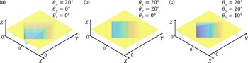
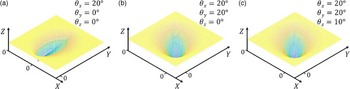
during the stage of peg moving [Reference Li and Qiao20]. Figure 3 illustrates the constraint regions of the nonconvex axisymmetric peg-in-hole assembly when the peg is rotated about a single axis, two axes, or three axes. It can be found that in the three cases, there are nonconvex areas in the constraint regions. When the peg is rotated about a single axis, the constraint region is symmetrically distributed about the coordinate axis. However, when the peg is rotated about two or three axes, the constraint regions have no obvious geometric features. From the perspective of assembly strategy design, it should be conducive to the analysis of constraint regions, strategy design, and operation simplicity to set the posture of the peg. Therefore, select the constraint region with the peg rotating about a single axis for analysis, for example, rotate the peg about
 ${\overrightarrow{{O_{p}Y_{p}}}}$
.
Constraint regions of the nonconvex axisymmetric peg-in-hole assembly when (a)
 $\theta =(20^{\circ},0^{\circ},0^{\circ})$
, (b)
 $\theta =(20^{\circ},20^{\circ},0^{\circ})$
, and (c)
 $\theta =(20^{\circ},20^{\circ},10^{\circ})$
.

The constraint region in configuration space of the peg and hole when
 $\theta =(0,\theta _{y},0)$
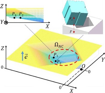
is shown as Fig. 4. It can be found that the constraint region contains a step-shaped nonconvex area
 $\Omega _{\mathrm{NC}}$
symmetric about
 ${\overrightarrow{{X}}}$
, and there exist nonstrictly stable points [Reference Qiao, Wang, Su, Jia and Li17] along
 ${\overrightarrow{{Z}}}$
direction in the area
 $\Omega _{\mathrm{NC}}$
. Taking the case in Fig. 4 as an example, the unit vector
 ${\overrightarrow{{e}}}$
is along
 ${\overrightarrow{{Z}}}$
direction; the point
 $O$
is the lowest point in the frame
 $O-XYZ$
; the point
 $P_{1}$
and point
 $P_{2}$
belong to
 $\Omega _{\mathrm{NC}}$
and satisfy
 ${\overrightarrow{{e}}}\cdot {\overrightarrow{{OP_{1}}}}={\overrightarrow{{e}}}\cdot {\overrightarrow{{OP_{2}}}}$
, thus
 $P_{1}$
and
 $P_{2}$
are nonstrictly stable points along
 ${\overrightarrow{{Z}}}$
direction. The contact state of the peg and the hole in the physical space corresponding to
 $P_{2}$
is shown in the upper right of Fig. 4. The quasi-static analysis illustrates that, under the input
 $F$
in
 $-{\overrightarrow{{Z}}}$
direction, the peg will be subjected to an equal reverse contact force
 $F_{c}$
. It means that the peg will be blocked during the assembly process and the position error cannot be dynamically eliminated, thus the assembly task assembly task will not be completed successfully.
The constraint region of the nonconvex axisymmetric parts.

In particular, when the reference cross-sectional shape of the peg is circular (X–Y axisymmetric
 $n$
polygon,
 $n\rightarrow \infty$
), the impact of the posture error about
 ${\overrightarrow{{O_{p}Z_{p}}}}$
that may be introduced during the grasping process needs to be considered. Because the volume of the groove area is very small, it requires high-precision sensing information and relatively complex algorithms to recognize the orientation of the peg. If the groove area is ignored, the posture of the peg is unable to be recognized. Therefore, a large posture error may be introduced in the process of grasping the peg, which will have a great impact on the shape of the constraint region and the design of the strategy based on ARIE.
For example, the assembly model of peg-in-hole where the peg is quasi-cylindrical with four grooves is shown in Fig. 5. Figure 6 illustrates the constraint regions of the quasi-cylindrical peg-in-hole assembly when the peg is rotated about a single axis, two axes, or three axes. In order to facilitate the strategy design and the implementation of assembly, rotate the peg about a single axis, such as
 ${\overrightarrow{{O_{p}Y_{p}}}}$
. Moreover, the influence of the orientation error about
 ${\overrightarrow{{O_{p}Z_{p}}}}$
on the constraint region is considered.
Coordinate systems established for the quasi-cylindrical parts.

Constraint regions of the quasi-cylindrical peg-in-hole assembly when (a)
 $\theta =(20^{\circ},0^{\circ},0^{\circ})$
, (b)
 $\theta =(20^{\circ},20^{\circ},0^{\circ})$
, and (c)
 $\theta =(20^{\circ},20^{\circ},10^{\circ})$
.

Let
 $\theta _{x}$
and
 $\theta _{y}$
remain unchanged and
 $\theta _{Z}$
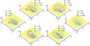
change uniformly. The corresponding constraint regions are shown in Fig. 7. When
 $\theta =(0,20^{\circ},0)$
, the nonconvex region
 $\Omega _{\mathrm{NC}}$
is symmetrically distributed about
 ${\overrightarrow{{X}}}$
axis. Keep
 $\theta _{x}$
and
 $\theta _{y}$
unchanged, as
 $\theta _{Z}$
increases from 0,
 $\Omega _{\mathrm{NC}}$
moves toward
 ${\overrightarrow{{Y}}}$
as a whole and is divided into two areas: the Y-positive area and the Y-negative area. The volume of the Y-positive area gradually increases, while the volume of the Y-negative area gradually decreases. Let
 $\theta _{Z}$
take a set of opposite numbers, the shapes of the two constraint regions are symmetric about
 ${\overrightarrow{{X}}}$
axis. Here, because the four grooves are
 $90^{\circ}$
angular symmetric with respect to the geometric center of the peg, when
 $\theta =(0,20^{\circ},\pm 45^{\circ})$
, the shapes of the two constraint regions are the same, and there is no nonconvex area.
Constraint regions of the quasi-cylindrical peg-in-hole assembly when
 $\theta _{x}=0, \theta _{y}=20^{\circ},$
 $\theta _{z}=0,\pm 15^{\circ},\pm 30^{\circ},\pm 45^{\circ}$
.

To sum up, due to the single input direction in the classic strategy based on ARIE, the nonconvex structure on the peg may cause the peg to be stuck during the moving process, thus the task cannot be finished successfully. In addition, if there exists a large error in the axial posture of the peg, the distribution of nonconvex areas in the constraint region is of great uncertainty. In other words, the uncertainty of the axial posture of the peg will lead to the uncertainty of the position where the blocking occurs. Therefore, it is necessary to design a general assembly method to solve the problems.
3. Assembly strategy design
This section includes three aspects about the assembly strategy design. First, the nonconvex X–Y axisymmetric assembly constraint region is analyzed and some key geometric features are obtained. Second, a new multi-step sliding assembly strategy is proposed by utilizing low-dimensional attractive regions in the subspace of the constraint region. Third, impedance control is used to enable the peg to achieve the desired compliant motion in the proposed strategy. Theoretically, the peg can be prevented from being blocked in the assembly process, and the position error can be dynamically eliminated by using the new strategy.
3.1. Assembly modeling for the nonconvex X–Y axisymmetric parts
In the previous discussion about the relationship between the high-dimensional attractive region and the low-dimensional one, Qiao et al. pointed out that the 3D constraint region (or attractive region) may contain multiple 2D attractive regions, which is helpful to make feasible and reliable manipulation strategies in the low-dimensional configuration space [Reference Qiao, Wang, Su, Jia and Li17]. Inspired by this conclusion, we can design a series of 2D attractive regions in the low-dimensional subspace of the 3D constraint region. By designing different state-independent inputs for each 2D attractive region, the stable point of the former attractive region falls within the latter one. Thus, the peg can move directionally step by step under a series of simple inputs and environmental constraints, and finally reach the global lowest point.
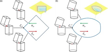
In another work about condition and strategy analysis for assembly based on ARIE, Li and Qiao further pointed out that the transversal-sectional shape (except the boundary state) of the constraint region is related to the shape of the hole. In particular, for round peg-in-hole assembly, the outline of the transversal section of the constraint region consists of three arcs (except the boundary state) [Reference Li and Qiao20]. Obviously, the conclusion is also applicable to the assembly where the transversal-sectional shape of the hole is X–Y axisymmetric convex polygon. As shown in Fig. 8, on the transversal section of the constraint region, there is a 2D attraction region along
 $\vec{e}_{tv}$
direction, where point
 $C_{2}$
(
 $C^{\prime}_{2}$
) is the strictly stable point corresponding to the two-point contact state. Therefore, when the noncritical peg-hole contact condition is satisfied, keep the peg fixed in posture and let it free in translation along the horizontal direction; then apply a transversal input
 ${\vec{u}_{tv}}$
, and the peg will finally keep stable in the two-point contact state. It should be noted that the convexity of the transversal section of the constraint region is only related to the shape of the hole, and the nonconvex structures on the peg do not affect geometric characteristics of the constraint region. In other words, the nonconvex structures on peg do not affect the existence of the transversal 2D attractive region.
(a) Transversal section (except the boundary state) of the constraint region of polygon parts; (b) Transversal section (except the boundary state) of the constraint region of cylindrical parts.

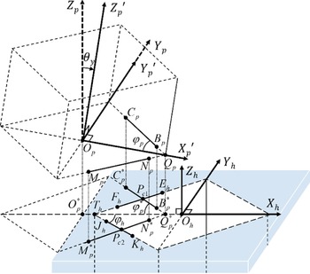
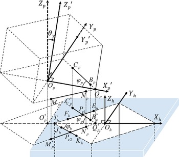
From the continuity of motion, it is obvious that when the nonconvex area is ignored, the peg maintains two-point contact with the hole and slides down, and finally reaches the three-point contact state (global minimum point). So, we considered to search the attractive region on the longitudinal section of the constraint region including the two-point contact state and the three-point contact state. The mathematical model of the peg-hole two-point contact state is established as shown in Fig. 9.
Mathematical model of two-point contact in the axisymmetric parts assembly.

The coordinates attached on the peg and the hole are
 $\{p\}$
and
 $\{h\}$
, respectively.
 $O_{p}$
is the geometric center of the lower surface of the peg, and
 $O_{h}$
is the geometric center of the upper surface of the hole. For the selection of the posture of the peg, it should be considered from the perspective of strategy design. The purpose of tilting the peg is to generate an appropriate constraint region conducive to assembly. According to the analysis of constraint regions in Section 2, an axisymmetric conical constraint region can be generated by rotating the peg about a single axis, which is conducive to modeling and analysis and is easy to operate in actual assembly. Therefore, it is advisable to take the rotation of the peg about
 ${\overrightarrow{{O_{p}Y_{p}}}}$
as an example to study the two-point contact state in the peg-in-hole assembly. Starting with the frame
 $O_{p}-X_{p}Y_{p}Z_{p}$
parallel to the frame
 $O_{h}-X_{h}Y_{h}Z_{h}$
, rotate the peg about
 ${\overrightarrow{{O_{p}Y_{p}}}}$
by an angle
 $\theta _{y}$
, and the orientation of the peg is described by the frame
 $O_{p}-X^{\prime}_{p}Y^{\prime}_{p}Z^{\prime}_{p}$
. The segment
 $B_{p}C_{p}$
and the segment
 $N_{p}M_{p}$
are two segments symmetrical about
 ${\overrightarrow{{O_{p}X^{\prime}_{p}}}}$
at the bottom edge of the peg. The straight line
 $B_{p}C_{p}$
and the straight line
 $N_{p}M_{p}$
intersect at the point
 $Q_{p}$
, and set the segment
 $O_{p}Q_{p}=r_{p}$
, and
 $\angle O_{p}Q_{p}C_{p}=\angle O_{p}Q_{p}M_{p}=\varphi _{p}$
. When the peg and the hole are in contact by two points, the segment
 $F_{h}E_{h}$
and the segment
 $J_{h}K_{h}$
are the two segments on the edge of the hole, which is related to the segment
 $B_{p}C_{p}$
and the segment
 $N_{p}M_{p}$
, respectively. The two contact points are
 $P_{c1}$
and
 $P_{c2}$
. The straight line
 $F_{h}E_{h}$
and the straight line
 $J_{h}K_{h}$
intersect at the point
 $T_{h}$
, and set the segment
 $O_{h}T_{h}=r_{h}$
, and
 $\angle O_{h}T_{h}E_{h}=\angle O_{h}T_{h}K_{h}=\varphi _{h}$
. The projections of the segment
 $B_{p}C_{p}$
and
 $N_{p}M_{p}$
, the point
 $Q_{p}$
and
 $O_{p}$
on
 $X_{h}O_{h}Y_{h}$
plane are the segment
 $B_{p}^{*}C_{p}^{*}$
and
 $N_{p}^{*}M_{p}^{*}$
, the point
 $Q_{p}^{*}$
and
 $O_{p}^{*}$
, respectively, where
 $\angle C_{p}^{*}Q_{p}^{*}O_{p}^{*}=\angle M_{p}^{*}Q_{p}^{*}O_{p}^{*}=\varphi _{p}^{*}$
.
The position of the geometric center of the lower surface of the peg in the frame
 $\{h\}$
is described by
 ${}^{h}{P}{_{Op}^{}}=(x_{{O_{p}}},y_{{O_{p}}},z_{{O_{p}}})$
. When the peg and the hole are in contact by two points, the equations are obtained to get
 ${}^{h}{P}{_{Op}^{}}$
as the following:
Equation of the line
 $F_{h}E_{h}$
:
 \begin{equation} y=\left(x+r_{h}\right)\tan \varphi _{h} \end{equation}
Equation of the line
 $B_{p}^{*}C_{p}^{*}$
:
 \begin{equation} y=-\left(x-x_{{O_{p}}}-r_{p}\cos \theta \right)\tan \varphi _{p}^{*} \end{equation}
where
 $\tan \varphi _{p}^{*}=\frac{\tan \varphi _{p}}{\cos \theta _{y}}, \varphi _{p},\varphi _{h},\theta _{y}\in \left(0,\frac{\pi }{2}\right)$
.
For the two-point contact state, the trigonometric relationship exists as following:
 \begin{equation} \tan \theta _{y}=\frac{\left| z_{{O_{p}}}\right| }{\left| x_{{O_{p}}}\right| -\left| x_{{P_{c1}}}\right| } \end{equation}
where
 $x_{{P_{c1}}}$
is the coordinate of the contact point
 $P_{c1}$
in the
 ${\overrightarrow{{O_{h}X_{h}}}}$
direction in the frame
 $\{h\}$
.
The result is obtained from symmetry and Eqs. (1)–(3):
 \begin{equation} {}^{h}{P}{_{Op}^{}}=\left(x_{{O_{p}}},0,-\frac{\sin \theta _{y}\tan \varphi _{h}}{\cos \theta _{y}\tan \varphi _{h}+\tan \varphi _{p}}x_{{O_{p}}}+\frac{r_{p}\sin \theta _{y}\tan \varphi _{p}-r_{h}\sin \theta _{y}\tan \varphi _{h}}{\cos \theta _{y}\tan \varphi _{h}+\tan \varphi _{p}}\right) \end{equation}
When the cross-sectional shape is X–Y axisymmetric, we can obtain
 $\varphi _{p}=\varphi _{h}$
. For the parts with approximately equal size, assume that
 $r_{p}=r_{h}$
. The further result is obtained from Eq. (4):
 \begin{equation} {}^{h}{P}{_{Op}^{}}=\left(x_{{O_{p}}},0,-x_{{O_{p}}}\tan \frac{\theta _{y}}{2}\right) \end{equation}
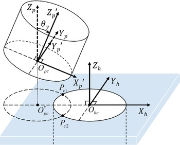
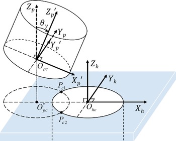
Particularly, for axisymmetric parts assemblies with circular cross-sections, the mathematical model of the peg-hole two-point contact state is established as shown in Fig. 10. The coordinates attached on the peg and the hole are
 $\{p\}$
and
 $\{h\}$
, respectively.
 $O_{pc}$
is the geometric center of the lower surface of the peg, and
 $O_{hc}$
is the geometric center of the upper surface of the hole. The radii of the peg and the hole are
 $r_{p}$
and
 $r_{h}$
, respectively. Starting with the frame
 $O_{pc}-X_{p}Y_{p}Z_{p}$
parallel to the frame
 $O_{hc}-X_{h}Y_{h}Z_{h}$
, rotate the peg about
 ${\overrightarrow{{O_{pc}Y_{p}}}}$
by an angle
 $\theta _{y}$
, and the orientation of the peg is described by the frame
 $O_{pc}-X^{\prime}_{p}Y^{\prime}_{p}Z^{\prime}_{p}$
. The ellipse
 $O_{pc}^{*}$
is the projection of the lower surface of the peg on the plane
 $X_{h}O_{hc}Y_{h}$
. The two contact points are
 $P_{c1}$
and
 $P_{c2}$
. The position of the geometric center of the lower surface of the peg in the frame
 $\{h\}$
is described by
 ${}^{h}{P}{_{Op_{c}}^{}}=(x_{{O_{pc}}},y_{{O_{pc}}},z_{{O_{pc}}})$
. For a pair of peg and hole with approximately equal radius in high-precision assembly, assume that
 $r_{p}=r_{h}=r$
. When the peg and the hole are in contact by two points, the equations are obtained to get
 ${}^{h}{P}{_{Op_{c}}^{}}$
as the following:
Mathematical model of two-point contact in the cylindrical parts assembly.

Equation of the circle
 $O_{hc}$
:
 \begin{equation} x^{2}+y^{2}=r^{2} \end{equation}
Equation of the ellipse
 $O_{pc}^{*}$
:
 \begin{equation} \frac{\left(x-x_{{O_{pc}}}\right)^{2}}{\left(r\cos \theta _{y}\right)^{2}}+\frac{y^{2}}{r^{2}}=1 \end{equation}
where
 $\theta _{y}\in \left(0,\frac{\pi }{2}\right)$
.
The two contact points
 $P_{c1}$
and
 $P_{c2}$
are symmetrical about
 ${\overrightarrow{{O_{hc}X_{h}}}}$
, so we can obtain
 $x_{{P_{c1}}}=x_{{P_{c2}}}, y_{{P_{c1}}}=-y_{{P_{c2}}}$
, and
 $z_{{P_{c1}}}=z_{{P_{c2}}}=0$
. Then, from Eqs. (6) to (7), the coordinate of
 $P_{c1}$
can be obtained:
 \begin{equation} P_{c1}=\left(\frac{x_{{O_{pc}}}}{1+\cos \theta _{y}},\sqrt{r^{2}-\left(\frac{x_{{O_{pc}}}}{1+\cos \theta _{y}}\right)^{2}},0\right) \end{equation}
For the two-point contact state, the trigonometric relationship exists as following:
 \begin{equation} \tan \theta _{y}=\frac{\left| z_{{O_{pc}}}\right| }{\left| x_{{O_{pc}}}\right| -\left| x_{{P_{c1}}}\right| } \end{equation}
The result is obtained from symmetry and Eqs. (8) and (9):
 \begin{equation} {}^{h}{P}{_{Op_{c}}^{}}=\left(x_{{O_{pc}}},0,-x_{{O_{pc}}}\tan \frac{\theta _{y}}{2}\right) \end{equation}
See Appendix for specific calculation process.
Equations (5) and (10) show that, on the longitudinal section of the constraint region including the two-point contact state and the three-point contact state, the set of
 ${}^{h}{P}{_{Op}^{}}$
(
 ${}^{h}{P}{_{Op_{c}}^{}}$
) is a straight-line segment with a slope of
 $-\tan\!(\theta _{y}/2)$
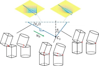
. Based on this important geometric property, the input
 ${\overrightarrow{u}_{lt}}$
in the longitudinal section can be designed with the angle between the direction and the horizontal plane of
 $\theta _{y}/2$
, as shown in Fig. 11. Under the action of
 ${\overrightarrow{u}_{lt}}$
, the peg is able to stride over the nonconvex areas without considering their distribution, and then reaches the three-point contact state
 $C_{3}$
. It should be noted that although the direction of
 ${\overrightarrow{u}_{lt}}$
is not vertical downward, for a small
 $\theta _{y}$
, the peg will stop moving and remain stable under the resistance of the inside of the hole after reaching the three-point contact state.
Longitudinal section of constraint region of the nonconvex axisymmetric polygon parts.

3.2. ARIE-based multi-step sliding strategy for nonconvex axisymmetric parts assembly
The classic ARIE-based assembly strategy contains two steps: (1) generate a constant force in the direction of
 $-{\overrightarrow{{O_{h}Z_{h}}}}$
to push the peg with a tilting posture angle into three-point contact state and (2) adjust the posture of the peg to finish the insertion.
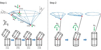
Based on the previous analysis in Section 3.1, an ARIE-based multi-step sliding strategy for nonconvex X–Y axisymmetric peg-in-hole assembly is proposed. As shown in Fig. 12, the new strategy includes two main steps: (Step 1) peg sliding with a tilting posture and (Step 2) posture adjustment. In Step 1, there are four substeps as following:
ARIE-based multi-step sliding strategy for nonconvex axisymmetric peg-in-hole assembly.

Step (1a): Move the peg to the area above the hole and keep it in a tilting posture. Then, apply the input
 ${\overrightarrow{u}_{0}}$
in the direction of
$-{\overrightarrow{{Z}}}$
to realize peg-hole one-point contact state;
Step (1b): Keep the peg fixed in posture while free in transversal movement and design the input
${\overrightarrow{u}_{1}}$
with a proper value in the direction of
$-{\overrightarrow{{X}}}$
. In the 2D attractive region parallel to the horizontal plane, the peg will be subjected to the combined effect of the input force and the contact force. As a result, the peg will move along the edge of the hole and reach the two-point contact state;Step (1c): Keep on the peg fixed in posture while free in transversal movement. Then, apply the obliquely downward input
${\overrightarrow{u}_{2}}$
whose direction is
$-\theta _{y}/2$
from the horizontal. Ideally, the peg is not subjected to the contact force, so that it is able to pass over the nonconvex areas and reach the three-point contact state;Step (1d): To enable the peg to keep stable at the global lowest point, the vertically downward input
${\overrightarrow{u}_{3}}$
can be applied. Due to the friction between the two parts,
${\overrightarrow{u}_{3}}$
is unnecessary in many cases.


By executing Step 1, the position error is eliminated and the blocking problem is avoided. Then, the posture of the peg can be adjusted by executing Step 2 and the assembly will be finished successfully.
3.3. Impedance control
Considering the motion requirements in the strategy based on ARIE, impedance control is a good choice because it can keep the peg (robot end-effector) posture fixed while motion relaxed in Cartesian space. The behavior of robot is compliant with impedance controllers. The imposed external force can cause the trajectory error of end-effector of robot. The dynamics model of impedance control is based on virtual springs and dampers, which have force change due to the difference between the measured states and the desired states of the end-effector [Reference Albu-Schäffer, Ott and Hirzinger29, Reference Ott, Schäffer, Kugi and Hirzinger30]. The characteristics of the system are described by Eq. (11):
 \begin{equation} M_{d}\!\left(\ddot{x}_{d}-\ddot{x}_{c}\right)+D_{d}\!\left(\dot{x}_{d}-\dot{x}_{c}\right)+K_{d}\!\left(x_{d}-x_{c}\right)=F_{d}-F_{ext} \end{equation}
where
 $x_{c}$
and
 $x_{d}$
are the initial desired position and the new desired position, respectively;
 $M_{d}$
is the inertial matrix;
 $D_{d}$
is the damping coefficient;
 $K_{d}$
is the stiffness parameters of the virtual mass-spring damper system;
 $F_{d}$
and
 $F_{ext}$
are the desired contact force and the detected external force, respectively.
4. Experiments and results
To test the effectiveness of the new method in the actual system, the peg-in-hole assembly platform is designed and the comparison experiments are carried out. Figure 13 shows the various components of the platform, which includes a 7 DOF robot (KUKA, LBR iiwa 14 R820), a six-dimension force sensor (OnRobot, HEX-E), two pneumatic grippers (SMC, MHS3-40D, MHS4-63D), a computer, a shell (hole), and an end-cap with grooves (peg). The position and posture information of the peg is obtained by inner sensors of the robot, and the contact force between the peg and the hole is monitored by the external force sensor. The robot is controlled through TCP/IP protocol suite from KUKA Sunrise Toolbox (KST)
Peg-in-hole robotic assembly platform.

ARIE-based classic algorithm for parts assembly

ARIE-based multi-step sliding algorithm for parts assembly

the peg and the hole. The diameter of the hole and peg are 57.76 and 57.74 mm, respectively. The width and depth of the groove on the peg are 4 and 2.5 mm, respectively. The axis of the hole is perpendicular to the horizontal plane. The Cartesian frame attached on the base of the robot is
 $\{r\}$
(
 $O_{r}-X_{r}Y_{r}Z_{r}$
).
4.1. Comparison experiments design
The purpose of the experiments is to verify the effectiveness of the new assembly method in solving the blocking problem caused by the nonconvex structures on the peg. The algorithms based on ARIE classic strategy and the new proposed multi-step sliding strategy are, respectively, given as Algorithms 1 and 2. Based on the same initial conditions, the new strategy is compared with ARIE-based classic strategy. Assumed that the location of the hole needs to be positioned by using visual information. When the accuracy of the sensor is low or signal drift exists, there is a large error between the measured hole position and the actual hole position, so it is impossible to directly use position control for high-precision assembly. However, within the error range, the projection of the lowest point on the peg with a tilting posture in the vertical direction is still inside the hole, which satisfy the applying condition of the ARIE-based strategy. In order to keep the peg fixed in orientation while free in translation, the impedance parameters are set as
 $K_{d}=\text{diag}([200,200,200,300,300,300])$
. The first three parameters are the stiffness coefficient of translation
 $C_{T}$
(unit: N/m), and the last three parameters are the stiffness coefficient of rotation
 $C_{R}$
(unit: Nm/rad). It should be noted that, in the KUKA controller, the values of stiffness coefficients of translation along or rotation about three axes are required to be equal.
 $M_{d}$
and
 $D_{d}$
are set as the robot system default values. Here present an explanation of the effect of stiffness parameter setting.
 $C_{T}$
and
 $C_{R}$
meet the formula
 $\Delta l=F_{E}/C_{T}$
and
 $\Delta \theta =T_{E}/C_{R}$
, respectively, where
 $F_{E}(F_{Ex},F_{Ey},F_{Ez})$
(unit: N) and
 $T_{E}(T_{Ex},T_{Ey},T_{Ez})$
(unit: Nm) are the external force and the torque of the end-effector in Cartesian coordinate system;
 $\Delta l(\Delta l_{x},\Delta l_{y},\Delta l_{z})$
(unit: m) and
 $\Delta \theta (\Delta \theta _{x},\Delta \theta _{y},\Delta \theta _{z})$
(unit: rad) are the translation change and the rotation change of the end-effector under the action of
 $F_{E}$
and
 $T_{E}$
, respectively. Taking
 $C_{T}=200$
N/m and
 $C_{R}=300$
Nm/rad as an example, assume that
 $F_{E}=(1,0,0)$
, the maximum force arm is about 0.27 m (the distance from the lower surface of the peg to the geometric center of the joint 6 of the robot), so the corresponding
 $T_{E}=(0,-0.27,0)$
, and we can obtain that
 $\Delta l=(0.005,0,0)$
and
 $\Delta \theta =(0,-0.0009,0)$
(about
 $-0.05^{\circ}$
). Therefore, in the contact process between the peg and the hole without blocking, under the action of a small external force (1N), the original desired trajectory of the peg can be changed relatively greatly (5 mm), so that the peg can slide smoothly along the edge of the hole. At the same time, under the action of the corresponding torque (0.27 Nm), the posture of the peg hardly changes (
 $0.05^{\circ}$
).
4.2. Experimental results
In the experiments, the position of the geometric center of the upper surface of the hole in the frame
 $\{r\}$
was set as
 ${{}^{r}}{P}_{{O}_{h}}=(453.3,-7.7,92.1)$
(unit:mm). The initial position error has been achieved by randomly changing the initial position of the peg within ± 40 mm along the radial direction of the hole.
A group of representative comparison experiments is selected here. The initial position and posture of the peg were set as
 ${{}^{r}}{P_{O_{p}0}}=(392.7,-4.3,122.5)$
and
 $\theta _{0}=(0,20^{\circ},0)$
, where there is a posture error
 $\Delta \theta _{z}\approx 10^{\circ}$
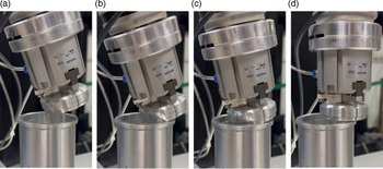
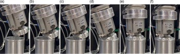
. The process of the assembly experiments with different strategies is shown, respectively, in Figs. 14 and 15.
Assembly process with ARIE-based classic strategy: (a) position and posture initialization, (b) one-point contact (blocking), (c) posture adjustment, and (d) insertion (failed).

Assembly process with ARIE-based multi-step sliding strategy: (a) position and posture initialization, (b) one-point contact, (c) two-point contact, (d) three-point contact, (e) posture adjustment, and (f) insertion.

In the assembly experiment with ARIE-based classic strategy, position error could not be eliminated because the peg was stuck by the groove, which ultimately led to assembly failure. In the assembly experiment with the new strategy, after the peg touched the hole by one point, the peg moved laterally to reach two points contact state. Then under the new input, it passed over the nonconvex area and reached the global lowest point. After adjusting the posture of the peg and insertion, the assembly was successfully complete. The trajectory and posture of the peg, and the information detected by the six-dimension force/torque sensor in the comparison experiments are shown in Figs. 16–19.
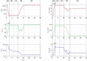
Position and posture of the peg when using ARIE-based classic strategy. (a) position and posture initialization, (b) approaching, (c) one-point contact (blocking), (d) posture adjustment, and (e) insertion (failed).

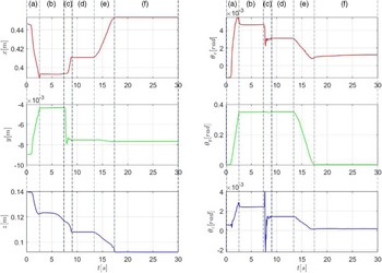
Position and posture of the peg when using ARIE-based multi-step sliding strategy. (a) position and posture initialization, (b) approaching, (c) sliding, (d) three-point contact, (e) posture adjustment, and (f) insertion.

Six-dimension force/torque information when using ARIE-based classic strategy. (a) position and posture initialization, (b) approaching, (c) one-point contact (blocking), (d) posture adjustment, and (e) insertion (failed).

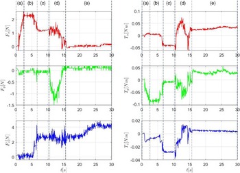
Six-dimension force/torque information when using ARIE-based multi-step sliding strategy. (a) position and posture initialization, (b) approaching, (c) sliding, (d) three-point contact, (e) posture adjustment, and (f) insertion.

Figures 16 and 17 record the position and posture information of the peg in the experiment based on ARIE classic strategy and multi-step sliding strategy, respectively. In the experiment based on ARIE classic strategy, the period of
 $t=0\sim 2.8$
s is for the position and posture initialization of the peg. When the peg reaches the initial position and posture (
 ${{}^{r}}{{P}_{O_{p}0}}=(392.4,-4.4,122.3)$
and
 ${{}^{r}}{\theta_{0}}=(0,20^{\circ},0)$
), keep the peg fixed in orientation while free in translation, and let it gradually approach the hole. Then, the first contact between the peg and the hole occurs at
 $t=6.5$
s, and the position of the peg is
 ${{}^{r}}{P}{_{Op1}^{}}=(392.2,-4.4,116.1)$
. Because the groove on the peg is stuck at the edge of hole, the peg is prevented from further sliding, and thus the position of the peg does not change in the period of
 $t=6.5\sim 10.5$
s. The algorithm misjudges that the peg has reached the global stable state or the position error has been eliminated, thus entering the stage of posture adjustment (
 $t=10.5\sim 15.5$
s). After adjusting the posture of the peg, the position and orientation of the peg are
 ${{}^{r}}{P}{_{Op2}^{}}=(442.9,-4.2,104.9)$
and
 ${{}^{r}}{\theta }{_{2}^{}}=(0,0,0)$
, respectively. The radial position deviation between the peg and the hole is about 11 mm (The coordinate of the hole
 ${{}^{r}}{P}_{{O}_{h}}=(453.3,-7.7,92.1), \Delta x=10.4$
mm and
 $\Delta y=3.5$
mm). The lower surface of the peg is in contact with the upper surface of hole, so the insertion cannot be completed and the assembly task fails.
In the experiment based on multi-step sliding strategy, similarly, the period of
 $t=0\sim 2.8$
s is for the position and posture initialization of the peg. When the peg reaches the initial position and posture (
 ${{}^{r}}{P^{\prime}_{O_{p}0}}=(393.0,-4.3,122.7)$
and
 ${{}^{r}}{\theta^{\prime}_{0}}=(0,20^{\circ},0)$
), keep the peg fixed in orientation while free in translation, and let it gradually approach the hole. When
 $t=7.5$
s, the peg touches the hole, and the position of the peg is
 ${{}^{r}}{P^{\prime}}{_{Op1}^{}}=(393.4,-4.3,116.3)$
. In the period of
 $t=7.5\sim 7.9$
s, the peg slides along the edge of the hole, moving 3.3 mm along
 $-{\overrightarrow{{O_{r}Y_{r}}}}$
and reached the two-point contact state. Then the peg continues to slide along the edge of the hole, moving 17.1 mm along
 ${\overrightarrow{{O_{r}X_{r}}}}$
and 7.6 mm along
 $-{\overrightarrow{{O_{r}Z_{r}}}}$
, respectively, and finally reaches the global lowest potential energy point
 ${{}^{r}}{P^{\prime}}{_{Op2}^{}}=(410.5,-7.5,108.0)$
at
 $t=8.9$
s. During
 $t=8.9\sim 13$
s, the position of the peg does not change significantly, thus entering the stage of posture adjustment (
 $t=13\sim 17.5$
s). With the correction of the posture of the peg, the peg-in-hole insertion is completed at
 $t=17.5$
s. The final position and orientation of the peg are
 ${{}^{r}}{P^{\prime}}{_{Opf}^{}}=(453.5,-7.7,92.1)$
and
 ${{}^{r}}{\theta^{\prime}}{_{f}^{}}=(0,20^{\circ},0)$
respectively, and the assembly task is finished successfully.
Comparing the position and orientation information of the two experiments, the main difference is whether there is a complete sliding stage. In the experiment based on ARIE classic strategy, due to the blocking problem, the expected sliding stage is not completed, which leads to misjudgment and premature entry into the stage of posture adjustment (at
 $t=10.5$
s), resulting in assembly failure. In the experiment based on the new strategy, the peg successfully slides to the global lowest potential energy point and enters the stage of posture adjustment at
 $t=13$
s. With the correction of the posture of the peg, the peg is inserted into the hole, and the assembly task is successfully completed.
Figures 18 and 19, respectively, record the six-dimension force information in the experiment based on ARIE classic strategy and multi-step sliding strategy. It should be noted that the force sensor has been zeroed before the experiment. The data detected in the experiment are raw data, including the influence of the gravity of the pneumatic gripper and the peg.
In the experiment based on ARIE classic strategy, the period
 $t=0\sim 2.8$
s is for the stage of initialization. In the process of reaching the predetermined initial state,
 $F_{y}$
and
 $F_{z}$
are basically kept near 0. Due to the gravity of the gripper and the peg,
 $F_{x}$
increases from 0 to about 2.2 N. The corresponding torques
 $T_{x}$
and
 $T_{z}$
vibrate slightly near 0, and
 $T_{y}$
changes from 0 to
 $-0.09$
Nm. When
 $t=6.5$
s, the first contact between the peg and the hole occurs, and the detected forces/torques change significantly. Subsequently, due to blocking, the forces/torques basically remain unchanged (
 $F_{x}\approx 1.2$
N,
 $F_{y}\approx 0$
N,
 $F_{z}\approx 2.8$
N,
 $T_{x}\approx -0.04$
Nm,
 $T_{y}\approx -0.007$
Nm, and
 $T_{z}\approx -0.028$
Nm) in the period of
 $t=7\sim 10.5$
s. Then, in the stage of posture adjustment (
 $t=10.5\sim 15.5$
s), the forces/torques fluctuate greatly. The maximum amplitude of contact force in one direction is about 2 N, and the maximum amplitude of torque is about 0.1 Nm. In the period of
 $t=15.5\sim 30$
s, the lower surface of the peg is in contact with the upper surface of the hole, and the insertion cannot be completed. The robot further applies a pressure along
 $-{\overrightarrow{{O_{r}Z_{r}}}}, F_{z}$
increases from about 2.7 N to about 4.2 N,
 $F_{x}$
and
 $F_{y}$
basically remain near 0,
 $T_{x}\approx 0.03$
Nm,
 $T_{y}\approx 0.03$
Nm, and
 $T_{z}\approx 0.004$
Nm.
In the experiment based on multi-step sliding strategy, similarly, the period
 $t=0\sim 2.8$
s is for the stage of initialization. In this period,
 $F_{y}$
and
 $F_{z}$
are basically kept near 0 and
 $F_{x}$
increases from 0 to about 2.3 N. The corresponding torques
 $T_{x}$
and
 $T_{z}$
vibrate slightly near 0, and
 $T_{y}$
changes from 0 to
 $-0.09$
Nm. When
 $t=7.5$
s, the first contact between the peg and the hole occurs, and the detected forces/torques change significantly. When
 $t=7.9$
s, there is a pulse of
 $F_{y}\approx 8$
N and
 $T_{x}\approx -0.175$
Nm,
corresponding to the collision between the peg and the hole when the peg slides to the two-point contact state. When
 $t=8.9$
s,
 $F_{x}, F_{z}$
and
 $T_{y}$
jump to about
 $-7$
N, 9 N and 0.736 Nm respectively, which corresponds to the collision between the peg and the hole when the peg slides down to the global lowest potential energy point. In the period of
 $t=8.9\sim 13$
s, the peg is kept in the stable contact state, and the forces/torques basically remain unchanged (
 $F_{x}\approx -2.9$
N,
 $F_{y}\approx 0.5$
N,
 $F_{z}\approx 2.6$
N,
 $T_{x}\approx 0.02$
Nm,
 $T_{y}\approx 0.35$
Nm,
 $T_{z}\approx 0.02$
Nm). The period of
 $t=13\sim 17.5$
s is for the posture adjustment, and the forces/torques fluctuate greatly. When
 $t=17.5$
s, the peg falls into the hole and
 $F_{z}$
declines from about 2.6 N to about 1.1 N. In the period of
 $t=17.5\sim 30$
s, the robot further applies a pressure along
 $-{\overrightarrow{{O_{r}Z_{r}}}}, F_{z}$
increases from about 1.1 N to about 2.7 N,
 $F_{x}\approx -2.2$
N,
 $F_{y}\approx -0.4$
N,
 $T_{x}\approx 0.01$
Nm,
 $T_{y}\approx 0.2$
Nm, and
 $T_{z}\approx -0.002$
Nm.
Comparing the six-dimension force information of the two experiments, it can be seen that in the experiment based on the classic strategy, due to the blocking problem, the expected sliding stage is not completed, and the force/torque change is relatively gentle in the whole process. In the experiment based on multi-step sliding strategy, the peg slides along the edge of the hole and collides with the hole, resulting in rigid impact. When it reaches the two-point contact state or the three-point contact state, large impact forces are generated.
5. Conclusion
In this paper, a compliant assembly method based on ARIE with geometric characteristics is proposed for the assembly of a class of nonconvex axisymmetric parts. Focusing on the possible blocking problem, the mathematical model of a class of axisymmetric parts assembly with nonconvex structure is established, and the assembly constraint region is analyzed in detail. Then, an ARIE-based multi-step sliding strategy for nonconvex axisymmetric parts assembly is proposed. By designing a series of 2D attractive regions in the subspace of 3D constraint region, the peg is enhanced in autonomy during the process of movement, so that it can pass over or get rid of the nonconvex areas. Furthermore, impedance control is used to enable the peg to achieve the desired compliant motion in the proposed strategy. Finally, comparison experiments of nonconvex parts assembly at micron scale are made, and the results show that the new strategy is effective in solving the blocking problem caused by the nonconvex structure. In the future work, we will further optimize the multi-step sliding strategy in terms of operation speed and contact force to meet the higher requirements for efficiency and quality in actual production. At the same time, we will also further study the 3D assembly modeling for complex structural parts and strategy design.
Author contributions
Hong Qiao and Yang Liu conceived and designed the study. Ziyu Chen and Shuai Gan programed and conducted the experiments. Yang Liu and Shuai Gan wrote the paper.
Financial support
This work was supported by Special Fund of State Key Laboratory of Management and Control for Complex Systems (Youth Foundation) (grant number 2022QN06).
Competing interests
The authors declare none.
A. Appendix
The mathematical model of the two-point contact between the end-surface of the peg and the edge of the hole is shown in Fig. A1.
Mathematical model of two-point contact in the axisymmetric parts assembly.

The coordinats attached on the peg and the hole are
 $\{p\}$
and
 $\{h\}$
, respectively.
 $O_{p}$
and
 $O_{h}$
are, respectively, the geometric centers of the lower surface of the peg and the upper surface of the hole. Starting with the frame
 $O_{p}-X_{p}Y_{p}Z_{p}$
parallel to the frame
 $O_{h}-X_{h}Y_{h}Z_{h}$
, rotate the peg about
 ${\overrightarrow{{O_{p}Y_{p}}}}$
by an angle
 $\theta _{y}$
, and the orientation of the peg is described by the frame
 $O_{p}-X^{\prime}_{p}Y^{\prime}_{p}Z^{\prime}_{p}$
. The segment
 $B_{p}C_{p}$
and the segment
 $N_{p}M_{p}$
are two segments symmetrical about
 ${\overrightarrow{{O_{p}X^{\prime}_{p}}}}$
at the bottom edge of the peg. The straight line
 $B_{p}C_{p}$
and the straight line
 $N_{p}M_{p}$
intersect at the point
 $Q_{p}$
, and set the segment
 $O_{p}Q_{p}=r_{p}$
, and
 $\angle O_{p}Q_{p}C_{p}=\angle O_{p}Q_{p}M_{p}=\varphi _{p}$
. When the peg and the hole are in contact by two points, the segment
 $F_{h}E_{h}$
and the segment
 $J_{h}K_{h}$
are the two segments on the edge of the hole, which are related to the segment
 $B_{p}C_{p}$
and the segment
 $N_{p}M_{p}$
, respectively. The two contact points are
 $P_{c1}$
and
 $P_{c2}$
. The straight line
 $F_{h}E_{h}$
and the straight line
 $J_{h}K_{h}$
intersect at the point
 $T_{h}$
, and set the segment
 $O_{h}T_{h}=r_{h}$
, and
 $\angle O_{h}T_{h}E_{h}=\angle O_{h}T_{h}K_{h}=\varphi _{h}$
. The projections of the segment
 $B_{p}C_{p}$
and
 $N_{p}M_{p}$
, the point
 $Q_{p}$
and
 $O_{p}$
on
 $X_{h}O_{h}Y_{h}$
plane are the segment
 $B_{p}^{*}C_{p}^{*}$
and
 $N_{p}^{*}M_{p}^{*}$
, the point
 $Q_{p}^{*}$
and
 $O_{p}^{*}$
, respectively, where
 $\angle C_{p}^{*}Q_{p}^{*}O_{p}^{*}=\angle M_{p}^{*}Q_{p}^{*}O_{p}^{*}=\varphi _{p}^{*}$
.
The position of the geometric center of the lower surface of the peg in the frame
 $\{h\}$
is described by
 ${}^{h}{P}{_{Op}^{}}=(x_{{O_{p}}},y_{{O_{p}}},z_{{O_{p}}})$
. When the peg and the hole are in contact by two points, use the projection method to get
 ${}^{h}{P}{_{Op}^{}}$
:
Equation of the line
 $F_{h}E_{h}$
:
 \begin{equation} y=\left(x+r_{h}\right)\tan \varphi _{h} \end{equation}
Equation of the line
 $B_{p}^{*}C_{p}^{*}$
:
 \begin{equation} y=-\left(x-x_{{O_{p}}}-r_{p}\cos \theta \right)\tan \varphi _{p}^{*} \end{equation}
where
 $\tan \varphi _{p}^{*}=\frac{\tan \varphi _{p}}{\cos \theta _{y}}, \varphi _{p},\varphi _{h},\theta _{y}\in \left(0,\frac{\pi }{2}\right)$
.
The coordinates of the contact point
 $P_{c1}$
are obtained from (A1) and (A2):
The side view of two-point contact state in the axisymmetric parts assembly.

 \begin{equation} x_{{P_{c1}}}=\frac{x_{{O_{p}}}\tan \varphi _{p}}{\cos \theta _{Y}\tan \varphi _{h}+\tan \varphi _{p}}+\frac{\cos \theta _{Y}\!\left(r_{p}\tan \varphi _{p}-r_{h}\tan \varphi _{h}\right)}{\cos \theta _{Y}\tan \varphi _{h}+\tan \varphi _{p}} \end{equation}
 \begin{equation} y_{{P_{c1}}}=\frac{x_{{O_{p}}}\tan \varphi _{p}\tan \varphi _{h}}{\cos \theta _{Y}\tan \varphi _{h}+\tan \varphi _{p}}+\frac{\cos \theta _{Y}\tan \varphi _{h}\left(r_{p}\tan \varphi _{p}-r_{h}\tan \varphi _{h}\right)}{\cos \theta _{Y}\tan \varphi _{h}+\tan \varphi _{p}}+r_{h}\tan \varphi _{h} \end{equation}
 \begin{equation} z_{{P_{c1}}}=0 \end{equation}
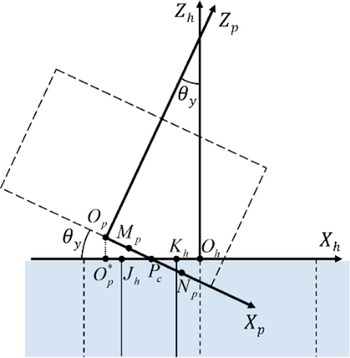
The side view of two-point contact state in axisymmetric parts assembly is shown as Fig. A2.
 $P_{c}$
is the projection of
 $P_{c1}$
on the plane
 $X_{h}O_{h}Z_{h}$
.
In the triangle
 $\bigtriangleup O_{p}O_{p}^{*}P_{c}$
,
 \begin{equation} \tan \angle O_{p}P_{c}O_{p}^{*}=\frac{\left| O_{p}O_{p}^{*}\right| }{\left| O_{p}^{*}P_{c}\right| } \end{equation}
where
 $\angle O_{p}P_{c}O_{p}^{*}=\theta _{y}$
, and
 $| O_{p}O_{p}^{*}| =| z_{{O_{p}}}|$
.
 \begin{equation} \left| O_{p}^{*}P_{c}\right| =\left| O_{p}^{*}O_{h}\right| -\left| P_{c}O_{h}\right| =\left| x_{{O_{p}}}\right| -\left| x_{{P_{c}}}\right| \end{equation}
The point
 $P_{c}$
is the projection of the point
 $P_{c1}$
on
 $X_{h}O_{h}Z_{h}$
plane, so
 \begin{equation} x_{{P_{c}}}=x_{{P_{c1}}} \end{equation}
From Eqs. (A3), (A6), (A7), and (A8),
 $z_{{O_{p}}}$
can be obtained:
 \begin{equation} z_{{O_{p}}}=-\frac{\sin \theta _{y}\tan \varphi _{h}}{\cos \theta _{y}\tan \varphi _{h}+\tan \varphi _{p}}x_{{O_{p}}}+\frac{r_{p}\sin \theta _{y}\tan \varphi _{p}-r_{h}\sin \theta _{y}\tan \varphi _{h}}{\cos \theta _{y}\tan \varphi _{h}+\tan \varphi _{p}} \end{equation}
Due to symmetry,
 \begin{equation} y_{{O_{p}}}=0 \end{equation}
The position of
 $O_{p}$
in the frame
 $\{h\}$
is obtained from Eqs. (A9) to (A10):
 \begin{equation} {}^{h}{P}{_{Op}^{}}=\left(x_{{O_{p}}},0,-\frac{\sin \theta _{y}\tan \varphi _{h}}{\cos \theta _{y}\tan \varphi _{h}+\tan \varphi _{p}}x_{{O_{p}}}+\frac{r_{p}\sin \theta _{y}\tan \varphi _{p}-r_{h}\sin \theta _{y}\tan \varphi _{h}}{\cos \theta _{y}\tan \varphi _{h}+\tan \varphi _{p}}\right) \end{equation}
Mathematical model of two-point contact in the cylindrical parts assembly.

Particularly, for axisymmetric parts assemblies with circular cross sections, the mathematical model of the peg-hole two-point contact state is established as shown in Fig. A3. The coordinates attached on the peg and the hole are
 $\{p\}$
and
 $\{h\}$
, respectively.
 $O_{pc}$
is the geometric center of the lower-surface of the peg, and
 $O_{hc}$
is the geometric center of the upper-surface of the hole. The radii of the peg and the hole are
 $r_{p}$
and
 $r_{h}$
, respectively. Starting with the frame
 $O_{pc}-X_{p}Y_{p}Z_{p}$
parallel to the frame
 $O_{hc}-X_{h}Y_{h}Z_{h}$
, rotate the peg about
 ${\overrightarrow{{O_{pc}Y_{p}}}}$
by an angle
 $\theta _{y}$
, and the orientation of the peg is described by the frame
 $O_{pc}-X^{\prime}_{p}Y^{\prime}_{p}Z^{\prime}_{p}$
. The ellipse
 $O_{pc}^{*}$
is the projection of the lower-surface of the peg on the plane
 $X_{h}O_{hc}Y_{h}$
. The two contact points are
 $P_{c1}$
and
 $P_{c2}$
. The position of the geometric center of the lower-surface of the peg in the frame
 $\{h\}$
is described by
 ${}^{h}{P}{_{Op_{c}}^{}}=(x_{{O_{pc}}},y_{{O_{pc}}},z_{{O_{pc}}})$
. For a pair of peg and hole with approximately equal radius in high-precision assembly, assume that
 $r_{p}=r_{h}=r$
. When the peg and the hole are in contact by two points, the equations are obtained to get
 ${}^{h}{P}{_{Op_{c}}^{}}$
as the following:
Equation of the circle
 $O_{hc}$
:
 \begin{equation} x^{2}+y^{2}=r^{2} \end{equation}
Equation of the ellipse
 $O_{pc}^{*}$
:
 \begin{equation} \frac{\left(x-x_{{O_{pc}}}\right)^{2}}{\left(r\cos \theta _{y}\right)^{2}}+\frac{y^{2}}{r^{2}}=1 \end{equation}
where
 $\theta _{y}\in \left(0,\frac{\pi }{2}\right)$
.
The two contact points
 $P_{c1}$
and
 $P_{c2}$
are symmetrical about
 ${\overrightarrow{{O_{hc}X_{h}}}}$
, so we can obtain
 $x_{{P_{c1}}}=x_{{P_{c2}}}, y_{{P_{c1}}}=-y_{{P_{c2}}}$
, and
 $z_{{P_{c1}}}=z_{{P_{c2}}}=0$
. Then, from Eqs. (6) to (7), the coordinate of
 $P_{c1}$
can be obtained:
 \begin{equation} P_{c1}=\left(\frac{x_{{O_{pc}}}}{1+\cos \theta _{y}},\sqrt{r^{2}-\left(\frac{x_{{O_{pc}}}}{1+\cos \theta _{y}}\right)^{2}},0\right) \end{equation}
The side view of two-point contact state in the cylindrical parts assembly.

 \begin{equation} P_{c2}=\left(\frac{x_{{O_{pc}}}}{1+\cos \theta _{y}},-\sqrt{r^{2}-\left(\frac{x_{{O_{pc}}}}{1+\cos \theta _{y}}\right)^{2}},0\right) \end{equation}
The side view of two-point contact state in axisymmetric parts assembly is shown as Fig. A4.
 $P_{c}$
is the projection of
 $P_{c1}$
on the plane
 $X_{h}O_{hc}Z_{h}$
.
In the triangle
 $\bigtriangleup O_{pc}O_{pc}^{*}P_{c}$
,
 \begin{equation} \tan \angle O_{pc}P_{c}O_{pc}^{*}=\frac{\left| O_{pc}O_{pc}^{*}\right| }{\left| O_{pc}^{*}P_{c}\right| } \end{equation}
where
 $\angle O_{pc}P_{c}O_{pc}^{*}=\theta _{y}$
, and
 $| O_{pc}O_{pc}^{*}| =| z_{{O_{pc}}}|$
.
 \begin{equation} \left| O_{pc}^{*}P_{c}\right| =\left| O_{pc}^{*}O_{hc}\right| -\left| P_{c}O_{hc}\right| =\left| x_{{O_{pc}}}\right| -\left| x_{{P_{c}}}\right| \end{equation}
The point
 $P_{c}$
is the projection of the point
 $P_{c1}$
on
 $X_{h}O_{hc}Z_{h}$
plane, so
 \begin{equation} x_{{P_{c}}}=x_{{P_{c1}}} \end{equation}
From Eqs. (A14), (A16), (A17), and (A18),
 $z_{{O_{pc}}}$
can be obtained:
 \begin{equation} z_{{O_{pc}}}=-x_{{O_{pc}}}\tan \frac{\theta _{y}}{2} \end{equation}
Due to symmetry,
 \begin{equation} y_{{O_{pc}}}=0 \end{equation}
The position of
 $O_{pc}$
in the frame
 $\{h\}$
is obtained from Eqs. (A19) to (A20):
 \begin{equation} {}^{h}{P}{_{Op_{c}}^{}}=\left(x_{{O_{pc}}},0,-x_{{O_{pc}}}\tan \frac{\theta _{y}}{2}\right) \end{equation}