Introduction
In satellite communications, dual-band filters are core to satellite-ground link signal routing, widely used in multi-band payload satellites. These filters separate signals in distinct frequency bands, simplifying transponder RF front-end cascades while reducing payload weight and power costs [Reference Guo and Wu1]. How to achieve small size and high performance remains a challenging topic. Conventional microstrip filters often suffer from complex structures [Reference Fu, Wu, Chen, Sun and Liang2–Reference Chuang and Wu4] and low-quality factors (Qu) [Reference Vélez, Sisó, Campo, Durán-Sindreu, Bonache and Martín5–Reference Guo, Zhu and Wong9], which limit their suitability for advanced communication systems.
Recently, many 3D printed cavity dual-band bandpass filters (BPFs) [Reference Guo, Wong and Zhu10–Reference Vaitukaitis, Nai and Hong13] have demonstrated superior quality factor, high precision, and low loss, such as rectangular, elliptical, and spherical BPFs. Among them, the spherical resonator has the highest Qu value. However, it still suffers from challenges in miniaturization and inadequate out-of-band selectivity. In [Reference Chen, Zhang, Hong, Sun, Yang, Tang and Feng14], a multi-mode resonance method is used to reduce the size of the filter, but this design lacks flexibility. In [Reference Li, Hong and Yuan15, Reference Feng, Zhang, Yang, Zhou and Hong16], a hemispherical resonant cavity is employed for filter design. It retains spherical resonators’ advantages and halves the size, but lacks transmission zeros (TZs) in the stopband. In [Reference Zhang, Feng, Chen, Yang, Zhu, Zhou, Hong, Tang and Yang17], a multimode multiplexing method is adopted to reduce the filter size and introduce transmission zeros simultaneously. Nevertheless, this method lacks universality.
In this letter, a compact hemispherical cavity resonator (HCR) topology and a general method for HCR to introduce multiple TZs are first proposed. Based on this, a novel 3D printed dual-band filter is designed and fabricated, which not only has a high isolation between two bands but also has a high selectiveness out of them. A dual-band BPF prototype operating at 9.1 and 9.77 GHz is fabricated by 3D printing process and measured, with measured results aligning closely with simulations.
Filter analysis and design
Hemispherical shunt resonators
As shown in Table 1, the HCR has the highest Q/volume, and the first spurious resonance is farther than other resonators. In addition, the rational configuration of HCRs may lead to a more compact filter structure. In this paper, the in-band zero method is proposed to design a dual-band filter [Reference Gao, Zhou and Huang18, Reference Vaitukaitis, Rao, Nai and Hong19]. It can be realized through a compound resonator topology (CRT). In Fig. 1(a) and (b) [Reference Macchiarella and Tamiazzo20], two HCRs are face-to-face parallel connected through a coupling iris, which presents two parallel and one series resonances. It can be used to realize a dual-frequency filter. In this compound resonator coupling topology, it is possible to realize N transmission zeros in each guard-band, where N is the order of each passband [Reference Vaitukaitis, Nai and Hong21].
Comparison of four types of cavity resonator

The compound resonator. (a) Compound resonator implemented by HCRs. (b) Prototype circuit of compound resonator [Reference Macchiarella and Tamiazzo20].

Dual-band filter design
Based on the above-mentioned analysis, a compact dual-band hemispherical cavity BPF is proposed by using three CRTs. The BPF operates at 9.1 and 9.77 GHz, with respective bandwidths of 210 and 200 MHz, and a passband return loss (RL) of less than 20 dB. The 3D geometric configuration of the proposed dual-band filter is shown in Fig. 2, and the filter’s physical dimensions are summarized in Table 2. It mainly consists of three sets of CRTs, four rectangular and three pairs of semi-cylindrical coupling irises. The coupling of three CRTs is achieved through rectangular iris structures, and the coupling strength is dependent on the iris’s length and width. In the CRTs, the coupling is realized by a pair of semicircular iris components; thus, the coupling value is decided by the irises’ radius and the spacing between them.
Geometric configuration of the dual-band BPF.

Main parameters of 3 order dual-band filter

The coupling topology is shown in Fig. 2. The calculated N + 2 coupling matrix [Reference Brand, Meyer and Geschke22]:
 \begin{equation}\left[ {\begin{array}{*{20}{c}}
0&{0.7412}&0&0&0&0&0&0 \\
{0.7412}&{ - 0.0306}&{0.4830}&0&{0.7276}&0&0&0 \\
0&{0.4830}&{ - 0.0306}&0&0&{0.7276}&0&0 \\
0&0&{0.4830}&{ - 0.0306}&0&0&{0.7276}&{0.7412} \\
0&{0.7276}&0&0&{0.0576}&0&0&0 \\
0&0&{0.7276}&0&0&{0.0576}&0&0 \\
0&0&0&{0.7276}&0&0&{0.0576}&0 \\
0&0&0&{0.7412}&0&0&0&0
\end{array}} \right]\end{equation}
In the Electromagnetic (EM) design, the external quality factor (Qe) is controlled by the area of the coupling apertures (ts  $ \times $hs), while the coupling coefficient (M) between cavities is tuned by varying the size of the coupling iris (t
 $ \times $h). The Qe and M values for the filter can be extracted using the following equations [Reference Hong and Lancaster23]:
 \begin{equation}M = \frac{{f_2^2 - f_1^2}}{{f_2^2 + f_1^2}}\quad \end{equation}
 \begin{equation}{Q_e} = \frac{{\pi {f_{{\tau _{max}}}} \cdot {\tau _{max}}}}{2}\end{equation}
where  ${f_1},{f_2},{\tau _{max}}$, and
 ${f_{{\tau _{max}}}}\,$are the resonant frequencies, the maximum group delay, and the frequency at
 ${\tau _{max}}$, respectively. The targeted Electromagnetic simulations were conducted to determine the required Qe and coupling coefficients M. Figure 3 displays the extracted Qe and M under different design parameters. Figure 3(a) exhibits M12 and M23 decline with increasing of h while increase with increasing of t. Similarly, as shown in Fig. 3(b), M14, M25, and M36 increase with increasing radius of semi-cylindrical coupling iris (vr) and length of two semi-cylindrical (vd). Figure 3(c) and (d) demonstrate an inverse correlation between Qe and rectangular coupling window dimensions, with Qe decreasing as length (ts) and width (hs) increase.
Coupling coefficients and external quality factor under different parameters. (a) Lengths t (h). (b) Lengths vr (vd). (c) Lengths ts (hs). (d) Lengths hs (ts).

As shown in Fig. 4, the matrix and EM simulations are in good agreement. There are two passbands centered at 9.1 and 9.77 GHz, with in-band return losses below −20 dB and −30 dB, respectively. Due to the CRT, three TZs are introduced between the two passbands.
S-parameters of extracted coupling matrix and simulation.

Enhanced out-of-band rejection
The initial design demonstrates an ideal in-band performance, but its out-of-band rejection still needs improvement. Introducing TZs is an effective strategy to improve out-of-band rejection. Unlike [Reference Vaitukaitis, Nai and Hong13, Reference Vaitukaitis, Rao, Nai and Hong19], as shown in Fig. 5(a) and (b), a novel resonant discontinuity in hemispherical resonators is proposed, it consists of a metal pillar, which not only can place the transmission zero very close to the passband but also much smaller.
HCR with Metal Pillar Incorporation. (a) Main view. (b) Side view.

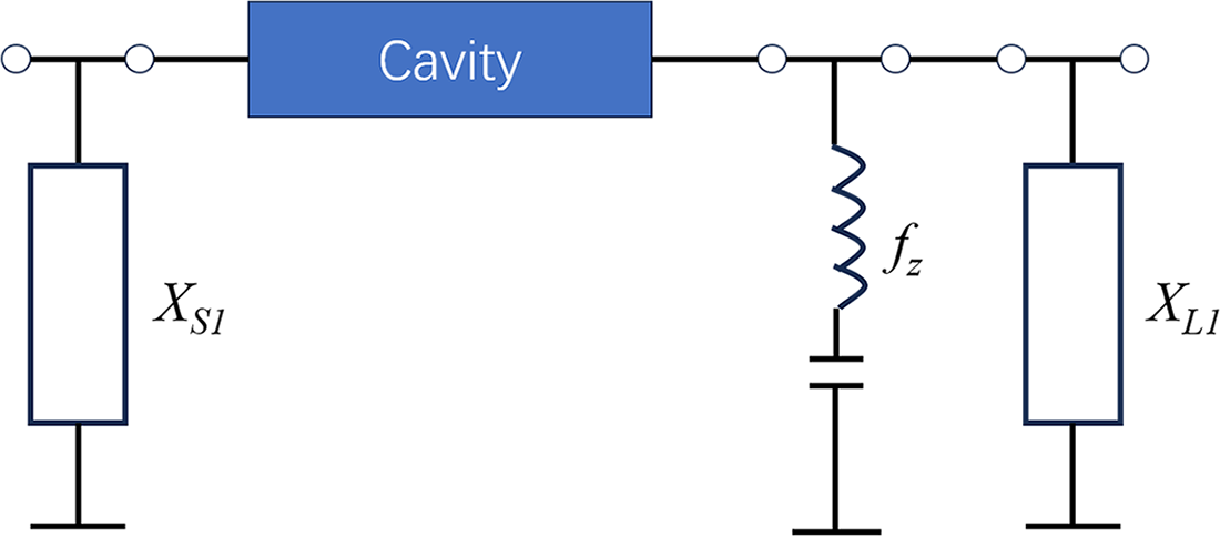
The electric field and magnetic field energy density distribution of this resonant discontinuity structure at the resonant frequency is shown in Fig. 6(a) and (b). The structure’s electric field energy is concentrated at the front end of the metal column, which can be equivalent to a capacitor; the magnetic field energy is concentrated at the tail end of the metal column, which can be equivalent to an inductor. From a circuit perspective, therefore, the resonant discontinuity can be represented by Fig. 7. The resonant frequency fz in the figure can be obtained using the following formula:
 \begin{equation}{X_s}\left( f \right) = - Im\left\{ {\frac{1}{2}\frac{{{S_{12}}}}{{{S_{11}}}}} \right\},{X_s}\left( {{f_z}} \right) = 0\end{equation}
Energy density of the resonant discontinuity structure. (a) The electric field. (b) The magnetic field.

The circuit of the resonant discontinuity structure.

where S11 and S21, respectively, represent the return loss and insertion loss in the filter’s transmission response. When the length d of the metal pillar in Fig. 5 is changed, the equivalent capacitance value and equivalent inductance value in Fig. 7 will also change. Therefore, the resonant frequency of this structure can be adjusted by modifying the length d of the metal pillar, and the position of the transmission zero introduced by this structure will shift accordingly. This change is clearly shown in Fig. 8(a) and (b).
Effect of the metal pillar length d on TZ. (a) The left side of the passband. (b) The right side of the passband.

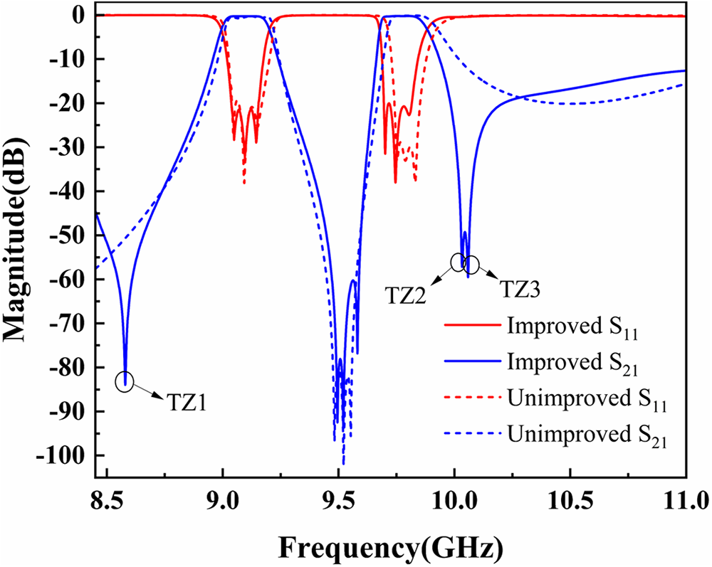
Based on the above, it optimizes the existing dual-band filter design and proposes the HCR dual-band filter with enhanced selectivity shown in Fig. 9. The original filter is modified by adding two pillars in cavity 1 and one in cavity 3. By optimizing the position and length of the three metal pillars, two TZs appear in the upper stopband and one in the lower. As shown in Fig. 10, the improved design demonstrates better S11 in-band, and its out-of-band rejection is also significantly improved.
Geometric configuration of the optimized dual-band filter. (a) Main view. (b) Section view.

S-parameters of improved filter and unimproved.

Fabrication and measurement
3D printing technology can directly print complex inner cavities (such as special-shaped resonant cavities and integrated coupling structures) that are difficult to mill using traditional CNC. It eliminates the need for multi-process splitting, and the integrated forming avoids cumulative errors caused by multi-process splicing in CNC machining. Since the delicate metal pillars are added to the filter, the selective laser melting (SLM) is chosen for the fabrication. The model with a normally selected 2.5 mm cavity thickness for optimal 3D printing was designed. The AlSi10Mg aluminum alloy powder is used for the fabrication. The photograph of the final fabricated dual-band BPF is shown in the inset of Fig. 11. Its final dimensions in Fig. 2 are as follows: r1 = 12.96, r2 = 12.745, r3 = 12.315, r4 = 12.945, r5 = 13.13, r6 = 13.08, ts = 15.11, hs = 4.53, t = 12.74, h = 9.58, vr = 6.75, vd = 1.98 (unit: mm).
Measured and simulated results.

As shown in Fig. 11, the measured results are in good agreement with the simulated ones. The dual-band BPF demonstrates center frequencies at 9.1 and 9.77 GHz, with 3dB bandwidths of 210 and 200 MHz, respectively. Measured insertion losses are 1.98 and 1.65 dB, while return losses exceed 20 dB. Moreover, three TZs appear at about 8.6, 10.04, and 10.1 GHz, respectively, bringing out good out-of-band rejection.
Finally, some comparisons between the proposed filter and the main previous dual-band filters are summarized in Table 3. From the comparisons, the advantages of this dual-band filter are obvious, such as low insertion loss, high attenuation between passbands and multiple TZs.
Comparison with previously reported 3D Printing Dual-band BPFs

Conclusion
This paper presents a novel design for a highly selective dual-band filter based on HCRs and CRT The filter achieves structural compactness through vertical resonator stacking, while the CRT enables design flexibility. The proposed TZ generation method can flexibly introduce multiple TZs and accurately adjust their positions. Then, a dual-band filter operating at 9.1 GHz and 9.77 GHz is 3D printed. Since the 3D printing technique achieves precise fabrication, the close agreement between measured and simulated results validates the design feasibility. This demonstrates the promising application prospects of the dual-band filter in multi-frequency communication systems.
Acknowledgment
This work was supported by the National Key R&D Program of China (2021YFC2902701).
Competing interests
The authors declare none.

Sheng Zhang received the Ph.D. degree in electronics science and technology from Shanghai University, Shanghai, China, in 2007. He is currently an Associate Professor at the School of Information and Control Engineering, China University of Mining and Technology (CUMT), Xuzhou, China. He has authored or coauthored over 40 journal and conference papers in this field. His current research interests include RF/microwave integrated circuits and antennas, especially in 3D metal printing and substrate-integrated waveguides.

Dan Li was born in 1999 and pursuing a master’s degree at the School of Information and Control Engineering, China University of Mining and Technology, his main research interests include high-Q waveguide filters based on 3D printing and microstrip technologies.

Mingzhong Fang was born in 2002 and is pursuing a master’s degree at the School of Information and Control Engineering, China University of Mining and Technology. His main research interests include metasurface antenna and microstrip technologies.

Zichun Zhang was born in 2000 and is pursuing master’s degree at the School of Information and Control Engineering, China University of Mining and Technology. His main research interests include filtering antennas and dipole principle.

Leichao Huang was born in 2000 and is pursuing master’s degree at the School of Information and Control Engineering, China University of Mining and Technology. His main research interests include eigenmode analysis and antenna technology.