
I. INTRODUCTION
Because of their advantages of thermal resistance, desirable mechanical properties, and biocompatibility,Reference Kurtz and Devine1–Reference Williams, Mcnamara and Turner3 semicrystalline thermoplastic polymers, such as poly(ether ether ketone) (PEEK), poly(ether ketone), and polyphenylene sulfide, have been used as replacements for metals in cars, aircraft, industrial pumps, and medical applications.Reference Vaezi and Yang4–Reference Kurtz7 In particular, in their medical implant applications, PEEK-like materials can successfully support radiographic assessment, which gives them an advantage over metals.Reference Kurtz7 These excellent performance characteristics of semicrystalline plastics are closely related to their semicrystalline forms, which are significantly influenced by the thermal cycles in the forming process.Reference Waddon, Hill, Keller and Blundell8–Reference Liu, Mo, Wang and Zhang12 Many industrial techniques have been used to manufacture products made of semicrystalline materials, such as injection molding, pressing, and sintering as well as emerging additive manufacturing processes.Reference Vaezi and Yang4,Reference Osswald, Baur, Brinkmann and Oberbach13,Reference Yang, Tian, Li, Cao, Zhao and Shi14 Compared to traditional manufacturing, additive manufacturing techniques such as selective laser sinteringReference Yan, Zhou, Tian, Peng, Cao and Li15,Reference Schmidt, Pohle and Rechtenwald16 and fused deposition modeling (FDM)Reference Xin, Sun, Yang, Peng, Hong-Bo and Jen-Taut17 provide an innovative and effective way to simplify processing and realize the manufacturing of complex structural parts of high-performance polymers.
Material extrusion, also known as FDM, can be used for rapid, inexpensive fabrication of thermoplastics. In the material extrusion process, the materials must be successively liquefied, rearranged, and then solidified; thus, they undergo a typical heating and cooling procedure,Reference Valentan, Kadivnik, Brajlih, Anderson and Drstvenšek18–Reference Wu, Geng, Zhao, Zhang, Rosen and Zhang20 which influences the product’s crystallinity and final properties, especially for semicrystalline materials.Reference Zalaznik, Kalin and Novak21
In the conventional semicrystalline material extrusion process, two problematic phenomena exist simultaneously. The internal crystallization is insufficient owing to too-rapid cooling without post-heat treatment or ambient heat treatment,Reference Yang, Tian, Li, Cao, Zhao and Shi14,Reference Gomes, Soares, Oliveira, Machado, Windmöller and Paranhos22,Reference Cebe and Hong23 whereas the external bonding strength of two adjacent layers is too low because of the low bonding temperature.Reference Kurapatti Ravi24–Reference Sun, Rizvi, Bellehumeur and Gu26 Increasing the ambient temperature seems to be the best solution to these two problems. The higher ambient temperature can effectively improve the internal crystallization of semicrystalline materials. However, it can also cause local volume contraction, which hinders effective interlayer bonding. Because of the requirement for high interlayer bonding strength, we can limit the crystallization, thereby reducing the material modulus, structural rigidity, and overall mechanical properties. Thus, the two requirements can be treated as an inherent trade-off, which requires further research to realize high-performance semicrystalline material extrusion manufacturing.
Therefore, a laser-assisted material extrusion process for PEEK-like semicrystalline materials has been proposed to ingeniously optimize the two supposedly conflicting parameters of interlayer bonding and crystallinity. Therefore, a material extrusion system was set up with a CO2 laser device. PEEK samples were prepared with and without laser assistance, and their interlayer shear strength and crystallinity were compared and analyzed.
In this paper, Sec. I gives an introduction to help understand why the research is needed. Section II gives the details about equipment setting up, materials, and methods to design samples and to implement the related tests. In Sec. III, the detailed test result and discussion are, respectively, presented. Then, Sec. IV provides a precise conclusion about the research. In addition, the acknowledgment and references cited in this paper are also to be listed in the end.
II. EQUIPMENT, MATERIALS, AND METHODS
A. Equipment and materials
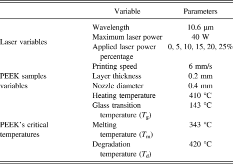
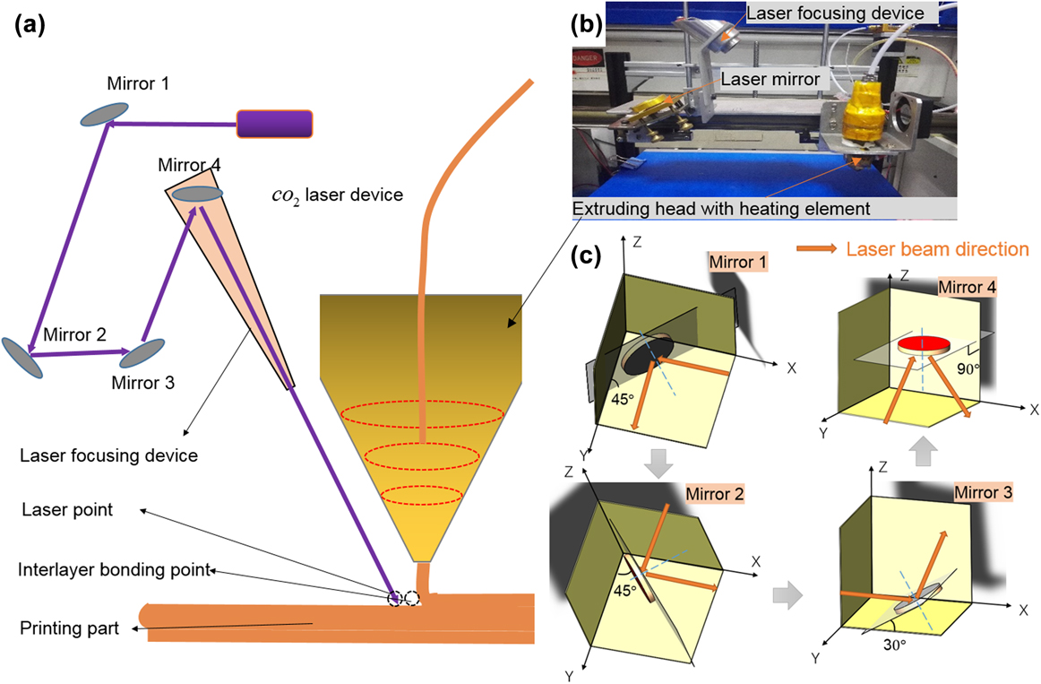
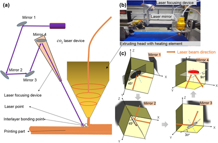
A CO2 laser device whose laser variables have been listed in Table I has been integrated into the traditional FDM printer system which has been reported before.Reference Magalhães, Volpato and Luersen27 As Fig. 1(a) shows, the laser beam is generated in the CO2 laser device; it is then reflected successively in mirror 1, mirror 2, mirror 3, and mirror 4, and finally focused on the part through the laser focusing lens. The CO2 laser and laser mirror 1 are fixed. Laser mirror 2 can move only in the Y direction. Furthermore, mirror 3, mirror 4, and the laser focusing device are rigidly connected to the nozzle to ensure synchronous movement. The end device, that is, the real equipment set-up in the laboratory, is also shown in Fig. 1(b). Each mirror’s placement angle has been schematically illustrated in Fig. 1(c).
Variables and parameters of the laser-assisted extrusion system.

Printer system and process. (a) Schematic of components and process of the printer system; (b) photograph of equipment; (c) schematic of mirror placement angle.

The PEEK filaments used in this paper were reprocessed from PEEK pellets (450 G, Victrex Corp., Thornton Cleveleys, United Kingdom). A few critical temperatures of PEEK and the basic process parameters of printing samples are also clearly listed in Table I, respectively.
B. Methods
A series of tests of the temperature, crystallinity, interlayer bonding, and microstructures were implemented to verify the validity of the proposed process.
1. Laser power control and thermal imaging
To study the relationship among the surface temperature, interlayer shear strength, crystallinity, and laser parameters, a laser was used at 5, 10, 15, 20%, and even higher percentages of its 40 W maximum power, and the laser powers are all simply referred to hereafter as 5, 10, 15, 20%, and so on, which are listed in Table I. Furthermore, the temperature under different laser power levels was measured using an infrared thermal imager (E50, FLIR Systems AB Corp., Stockholm, Sweden), whose optimum test temperature setting ranges from 120 to 650 °C.
2. Sample design
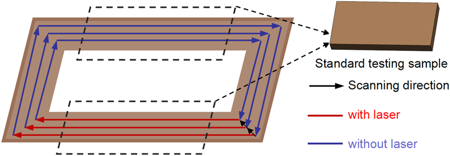
A printing sample was designed and printed as shown in Fig. 2. An annular rectangular part was designed to obtain a pair of contrasting samples. The nozzle follows the arrows moving in a circular path from the outside to the inside in each layer. During printing, the laser is controlled to be powered on one side (red lines) and off on the other sides; thus, the laser-on side always receives laser assistance, whereas the other sides receive no extra heating treatment. A pair of samples can be simultaneously obtained with and without laser-assisted heating for comparative study.
Diagram of the designed annular rectangular sample and the cut standard samples.

3. Short-beam test and SEM observation to assess interlayer bonding
According to the standard for interlayer shear strength testing by the short-beam method (JC/T 773-2010 GB Standard), a short-beam-shaped PEEK part is needed to implement a three-point bending test on a universal testing machine (PLD-5kN, LETRY Corp., Zi'an China). The sample length, sample width, sample thickness, pressure head diameter, span, and speed of pressurisation are approximately 20 ± 1 mm, 10 ± 0.2 mm, 2 ± 0.2 mm, 5 ± 0.2 mm, 10 mm, and 1 ± 0.2 mm/min, respectively. As shown in Fig. 2, after the annular rectangular part is printed, standard testing samples with a length of approximately 20 mm are cut from the long side. The width and thickness of the samples are approximately 10 and 2 mm, respectively. After the experiment, using the premeasured width (b/mm) and thickness (h/mm) and the yield force (F/N) obtained in the experiment, the interlayer shear strength (τm/MPa) can be calculated as
 $${\tau _{\rm{m}}} = {{3F} / {4bh}}\quad .$$
Five effective samples were prepared for testing with each parameter. Standard deviation was calculated for error analysis. Only one pair of standard samples with 25% laser power was prepared because of the degraded failure.
After testing, the samples were broken with brittle failure in liquid nitrogen. Then, the samples were plated with gold and put under scanning electron microscopy (SEM; SU8010, Hitachi Corp., Tokyo, Japan) to observe the microstructures of the fractured surfaces with an applied voltage of 20 kV and magnification of approximately 75 times.
4. Differential scanning calorimetry test to assess crystallinity
The degree of crystallinity χc of the samples was measured using a standard differential scanning calorimeter (DSC1, Mettler Toledo Corp., Zurich, Switzerland). All the samples were cut into small particles smaller than 1 mm in its longest size and then were heated at a rate of 10 °C/min to a temperature of 400 °C. The mass fraction of the crystalline region is then given by
 $${\chi _{\rm{c}}} = {{\left( {\Delta {H_{\rm{f}}} + \Delta {H_{\rm{c}}}} \right)} / {\Delta H_{\rm{f}}^0}}\quad ,$$
where ΔH f and ΔH c represent the measured values of the melting enthalpy and the cold crystallization exothermal energy, respectively.  $\Delta H_{\rm{f}}^0$ is the melting enthalpy of PEEK with 100% crystallinity and equals 130 J/g.Reference Blundell and Osborn28
III. RESULTS AND DISCUSSION
The relationship between preheating temperature and laser power is build up first because surface preheating temperature is the direct parameter to influence the crystallinity and interlayer bonding. Therefore, the relationship between crystallinity and preheating temperature is studied then, meanwhile the relationship between interlayer shear strength and preheating temperature is discussed to verify whether the improvement in interlayer bonding exists. Finally, a systematic discussion is presented to analyze the simultaneous improvement in both the interlayer bonding and the crystallinity.
A. Relationship between preheating temperature and laser power
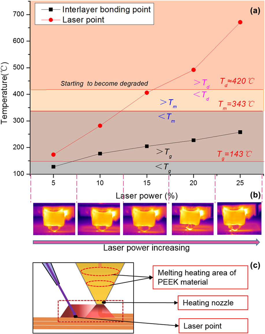
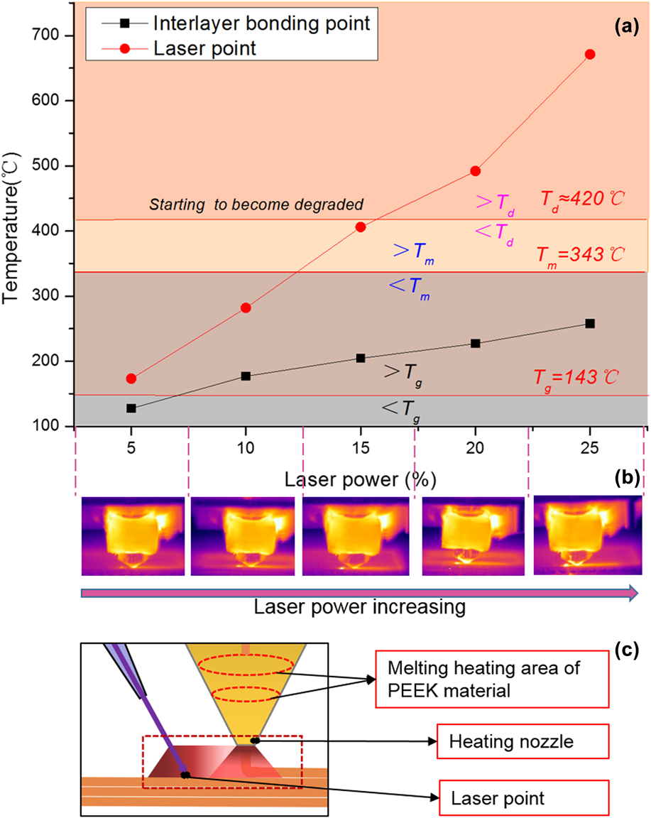
Temperature is the most directly measurable variable that represents different laser powers. Furthermore, to establish the relationship between the laser power and heating efficiency, the temperature distribution around the printing head was captured by using a thermal imaging device, as shown in Figs. 3(b) and 3(c). The laser point and heating nozzle can be clearly observed in Fig. 3(b) as two distinct local heated regions. The measured temperature is shown in Fig. 3(a). As the laser power increases, the temperatures of the laser point and interlayer bonding point marked in Fig. 1 are both increased. Several critical temperatures are marked in Fig. 3(a): the glass transition temperature (T g), melting temperature (T m), and degradation temperature (T d). Furthermore, Fig. 3(a) is divided into four important zones using these three temperatures to clarify the sample properties obtained using different laser parameters.
Effect of laser power on temperature. (a) Temperature of interlayer bonding point and laser point at different laser powers; (b) obtained by using an infrared thermal imager in different laser powers; and (c) schematic illustration of the terminal temperature distribution of the printer system.
B. Effect of laser preheating temperature on crystallinity
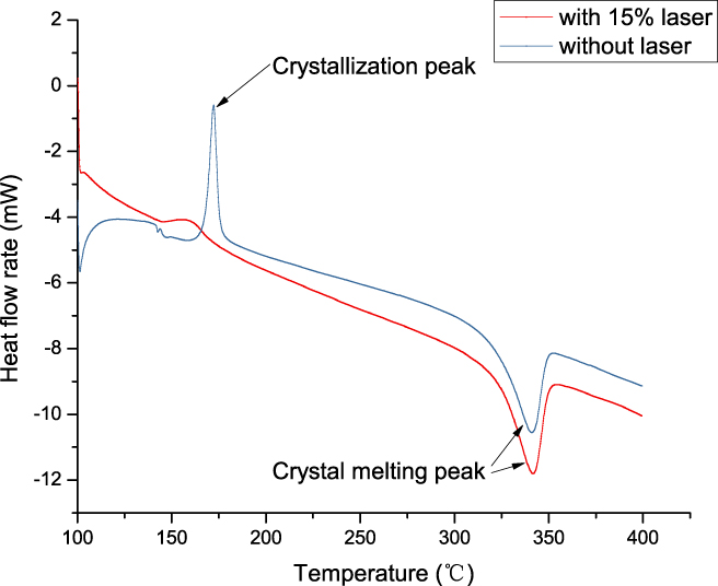
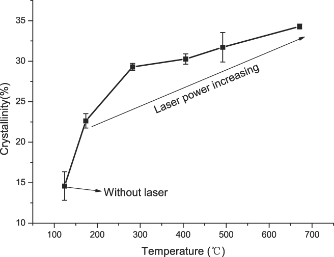
DSC analysis of the printed samples was performed. The blue curve in Fig. 4 shows a typical DSC curve of PEEK with quick cooling before laser treatment. The cold crystallization peak and crystal melting peak are clearly visible. However, after laser treatment, all the DSC curves at different laser power levels show only the crystal melting peak but no obvious cold crystallization peak, as the laser used in the process effectively supports catalysis during ongoing crystallization of the PEEK samples, which is interrupted by the high cooling rate during printing. As shown in Fig. 5, as the temperature increases, the crystallinity of the samples shows a corresponding increase. Without the laser, the crystallinity of PEEK is just retained at powers of less than 15%. With laser assistance, the much higher temperature improves the crystallinity to nearly 34.5%, which approaches to PEEK’s typical crystallinity of 35%.
Comparison of DSC curves for PEEK with and without laser assistance.

Controllable crystallization of PEEK specimens with different laser point temperatures.

Because PEEK is a semicrystalline thermoplastic material, its mechanical properties, including the elastic modulus and yield strength, are obviously influenced by the degree of crystallinity. Related research has been reported previously.Reference Kurtz and Devine1,Reference Yang, Tian, Li, Cao, Zhao and Shi14,Reference Chivers, Moore, Chivers and Moore29,Reference Jaekel, Macdonald and Kurtz30 In addition, some studies have reported that the cooling conditions are among the most essential factors controlling the crystallinity of PEEK-like semicrystalline materials.Reference Cebe and Hong23 When the cooling rate is high enough, amorphous PEEK can even be obtained.Reference Cebe and Hong23 Furthermore, some research has reported that an obvious improvement in crystallinity can be obtained when the cooling temperature is above 200 °C.Reference Jaekel, Macdonald and Kurtz30
Therefore, unlike ambient heat treatment controlReference Yang, Tian, Li, Cao, Zhao and Shi14,Reference Wu, Geng, Zhao, Zhang, Rosen and Zhang20 and post-heat treatment control,Reference Yang, Tian, Li, Cao, Zhao and Shi14,Reference Cebe and Hong23 the laser-assisted process affects the cooling conditions in a certain region, thus realising controllable crystallinity. As the regional temperature values in Fig. 3(a) show, with increasing laser power, the temperature of the laser point is obviously increased. Thus, the temperature change due to laser assistance is the only factor affecting the PEEK cooling process, which in turn influences the crystallinity. Furthermore, the monotonous curves in Figs. 5 and 3(a) all powerfully demonstrate the mapping relationship among the laser power, temperature, and crystallinity. Therefore, to realize crystallinity control, adjusting the corresponding laser parameters such as the laser power to change the temperature is an effective and simple method. Furthermore, the ability to control the crystallinity suggests promising engineering applications in multifunction integration manufacturing using semicrystalline thermoplastics, such as structures with variable stiffness or modulus.
C. Effect of laser preheating temperature on interlayer bonding
1. Interlayer shear strength
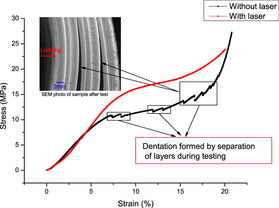
The interlayer shear strength was measured as an appropriate testing method to assess the interlayer bonding effect. The force–displacement curve is obtained by performing a three-point bending test on a universal testing machine, and then the stress–strain curve is obtained, as shown in Fig. 6, by calculation using Eq. (1). After fitting the curve to form a smooth curve, the second derivative should be obtained to determine the yield point, at which the derivative’s value is zero. Then, the yield force and yield strength are obtained from the force–displacement curve and stress–strain curve, respectively.
Comparison of change in force with increasing displacement with and without laser assistance at 15%.

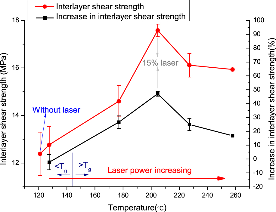
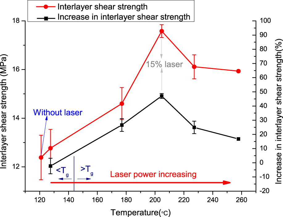
As Fig. 6 shows, the yield strength is obviously higher and the entire curve is much smoother after laser assistance. Furthermore, in the curve for the material without laser assistance, dentation forms when different layers become separated. The measurement data for the interlayer shear strength are shown in Fig. 7. When the temperature of the laser point is less than T g, the process provides little improvement in the interlayer bonding. Furthermore, as the temperature increases above T g, the interlayer shear strength obviously improves. However, the optimal bonding performance appears at a laser power of 15%, and the interlayer shear strength can improve by more than 45%, as shown in Fig. 7, which strongly indicates the potential of high-performance additive manufacturing using PEEK-like semicrystalline thermoplastics.
Interlayer shear strength and percentage increase of interlayer shear strength with different interlayer bonding point temperatures.
2. Microstructure
Several researchers have reported that the main effect of an air gap in thermoplastic additive manufacturing is to degrade the mechanical properties.Reference Vaezi and Yang4,Reference Ahn, Montero, Dan, Roundy and Wright31,Reference Ziemian, Sharma and Ziemian32 As shown in Fig. 8(b), there are many obvious air gaps between filaments. Furthermore, the laser-assisted process used in this study aims to narrow or even eliminate the air gaps to improve the interlayer bonding, as shown in Fig. 8(c). Therefore, the microstructure on the fractured cross section and the side surface of the prepared PEEK samples was observed, as shown in Fig. 8, to verify the interlayer bonding effect. Figure 8(d) shows a few crack-like interfaces inside the green frames. In comparison, with laser processing at 15%, a much neater fractured cross section similar to that in Fig. 8(c) is observed, as shown in Fig. 8(e). On the side surfaces, the visible thickness of each layer changes after laser assistance at 15%. Without laser treatment, the side surface shows a regular thickness and obvious interface, as shown in Fig. 8(f). With laser treatment at 15%, however, the thickness and the interface cannot be easily distinguished. Thus, the SEM photos all powerfully support the improvement in the interlayer bonding.
Schematic diagrams and SEM photographs of the interlayer bonding. (a) Illustration of the method by which corresponding planes are obtained. Fracture morphology (b) before and (c) after laser implementation. SEM photographs of (d) fractured cross section without laser, (e) fractured cross section with laser at 15%, (f) side surface without laser, and (g) side surface with laser at 15%.

D. Discussion
1. Interlayer bonding
There is reportedly a critical temperature that affects the interpenetration of molecular chains across a bonding interface.Reference Partain33 Furthermore, T g has been proven to be the critical temperature at which interface disappearance and bond development in thermoplastic materials are facilitated during material extrusion manufacturing.Reference Kurapatti Ravi24,Reference Anitha, Arunachalam and Radhakrishnan34 In recent years, there have been many studies on improving the interlayer strength of amorphous materials such as acrylonitrile-butadiene-styrene (ABS) and polylactic acid,Reference Kurapatti Ravi24–Reference Sun, Rizvi, Bellehumeur and Gu26 and the flexural strength of extruded ABS material components can be increased to a maximum of 95% by in situ heating.Reference Kurapatti Ravi24 Unlike the case for amorphous materials, delamination is always obvious in semicrystalline materials,Reference Vaezi and Yang4 and it is usually the primary form of failure in PEEK-like semicrystalline materials in a bending process. As mentioned above, delamination in semicrystalline material extrusion always occurs at the both macro and micro levels.
The laser acts as a regional heat source to improve interlayer bonding at two levels according to the delamination formation mechanics. Macroscopically, the laser heats the previous layer to form a regional molten bath that adaptively bonds with the melting printing layer as it decreases in volume. In addition, microscopically, the laser helps heat the bonding point in the previous layer to above T g to effectively improve the interpenetration of the molecular chain ends.Reference Partain33 As mentioned above and shown in Fig. 3(a), when the laser power is 5%, the temperature of the interlayer bonding point is smaller than T g, and there is no obvious improvement in the interlayer shear strength. However, at laser powers of 10 and 15%, the temperatures of the interlayer bonding point and laser point are both above T g and below T d. Furthermore, at 15% laser power, the temperature reaches the maximum within the effective range, and the interpenetration capacity of the molecular chain ends between two adjacent layers is highest. However, when the laser power exceeds 15%, the temperature of the laser point is so high that it causes degradation of the PEEK materials in the previous layer, resulting in reduction of the interlayer shear strength. A related discussion has been reported previously.Reference Fujihara, Huang, Ramakrishna and Hamada35 Therefore, maintaining a suitable heating temperature by laser power control could easily facilitate optimal interlayer bonding.
2. Simultaneous effect of laser on interlayer bonding and crystallinity
As an effective process, laser-assisted heat treatment has been widely used in tape placement.Reference Grouve, Warnet, Rietman, Visser and Akkerman36–Reference Parandoush, Tucker, Zhou and Lin39 By combining laser preheating and post-hot-rolling processes, the tape placement process can firmly bond a metal laminate and a plastic tape.Reference Grouve, Poel, Warnet and Akkerman37 The research reported here is successfully inspired by the concept of tape placement, where the laser-assisted heat treatment process is used to preheat the interlayer bonding points to a temperature exceeding T g, thereby greatly enhancing the cross-linking and interpenetration of molecular chains at the interface. At the same time, for semicrystalline materials, the crystallinity can be controlled by adjusting the laser power to achieve controllability of the material modulus and rigidity of the components. Therefore, this is the first time that a simple process has been used to improve the interlayer shear strength and realize regional controllability of the crystallinity simultaneously for PEEK-like semicrystalline materials.
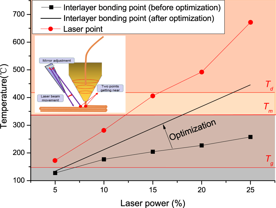
As mentioned above, T g and T d are the two most critical temperatures that influence the interlayer bonding effect. Unlike T g at the interlayer bonding point, T d usually appears at the laser point where the surface temperature is highest. Therefore, a reasonable optimization such as closing the distance between the laser point and the heating nozzle could be further performed to increase the temperature of the interlayer bonding point at the same laser power. When the laser power remains the same, the temperature–laser power curve of the laser point should never change, as shown in Fig. 9. Thus, at this point, the two curves should approach each other. Furthermore, at a lower laser power, a higher effective temperature of the interlayer bonding point could have been obtained to further improve the interlayer shear strength. In addition, as reported previously, the thermal distribution during the process strongly influences the crystallinityReference Sun, Rizvi, Bellehumeur and Gu26 so heating zone adjustment might also influence the crystallinity. Therefore, further research about different parameters, such as laser focusing angle, laser power, printing speed, and so on, should be systematically studied to build up a clearer mapping relationship between different parameters and the sample’s properties. The relationship would effectively guide us to realize an accurate control for interlayer bonding and crystallinity.
Optimization of the temperature–laser power curve.

IV. CONCLUSION
The interlayer shear strength and crystallinity of PEEK-like semicrystalline materials usually have conflicting manufacturing requirements so most processes optimize one parameter at the expense of the other. In this paper, a laser-assisted material extrusion process for PEEK has been demonstrated to effectively improve both the interlayer shear strength and the crystallinity simultaneously. The interlayer shear strength can be improved by more than 45%; furthermore, the crystallinity was more than two times higher than that obtained without the laser treatment and approached to the typical crystallinity of 35%. Furthermore, the mapping relationship between various laser parameters and the performance of the produced components has been successfully established to help realize controllability of the interlayer shear strength and local control of the crystallinity by adjusting the laser power within the effective range. On the basis of these results, an optimization of the process has been discussed to support future work in further improving both properties.
ACKNOWLEDGMENTS
This work was supported by the National Natural Science Foundation of China (No. 51575430) and National Key Research and Development Program of China (Nos. 2017YFB1103401 and 2016YFB1100902).