I. INTRODUCTION
Electrospinning (ES) is often used for fabrication of nanometer-sized fibrous materials due to its simplicity, low cost and flexibility. Ceramic fibers have been used as catalysts and photocatalysts,Reference Formo, Peng, Lee, Lu, Yang and Xia1–Reference Zhan, Chen, Jiao and Tao4 photoelectrodes,Reference Song, Kim, Ihn, Jo and Kim5–Reference Zhang, Zhu, Liu, Liu and Ramakrishna10 battery electrodes,Reference Gu, Chen and Jiao11 and more. Iron oxide based fibers are recently getting increased attention due to their potential application as sensors, hollow fiber anodes in lithium ion batteries, heavy metal ions adsorbents and catalysts.Reference Zheng, Li, Zhang, Wang, Wang and Wang12–Reference Shao, Zhang, Chen, Liu, Ji, Zhu and Feng20 When multicomponent compounds are needed, ideal homogeneity of the starting materials can be achieved via solutions, where all precursors and polymers are dissolved in the same solvent. However, unlike electrically conducting or piezoelectric fibers, where high fiber density is required, catalytic fibers could benefit from open porosity on their surface that makes the internal fiber surface more accessible.
Reports on ES of iron-oxide fibers containing crystalline Fe2O3 without subsequent thermal treatment are numerous.Reference Luoh and Hahn14,Reference Sung, Ahn and Kang21–Reference Bai, Zhang, Ning, Zhang, Nishi and Tian24 Post ES thermal treatment was applied when the soluble salts such as ferric nitrateReference Zheng, Li, Zhang, Wang, Wang and Wang12,Reference Fan, Zhang, Xu and Lv13,Reference Shao, Zhang, Chen, Liu, Ji, Zhu and Feng20 and ferric acetylacetonate (Fe(acac)3)Reference Zhang, Liu, Petnikota, Ramakrishna and Fan16–Reference Sundaramurthy, Kumar, Kalaivani, Thavasi, Mhaisalkar and Ramakrishna19 were used as the iron oxide source. However, the effects of precursor composition and process conditions on the final fiber structure are unknown. Specifically, the possibility to create these ceramic nanofibers with open mesoporosity has not been reported. Understanding of these issues is of paramount importance before potential application of these fibrous materials, particularly as catalysts can be fully exploited.
The aim of this work is to create nanofibers that have a mesoporous structure. The specific iron-based system developed here is aimed at heterogeneous hydrogenationReference Landau, Vidruk and Herskowitz25 of CO2 into hydrocarbon fuels. The majority of catalysts used in this case utilize Fe oxides with electronic promoters (K+, Na+) and structural promoters (Al2O3, SiO2).Reference Morales, Weckhuysen, Spivey and Dooley26 We developed two types of precursors and investigated the effect of ES conditions and precursor type on the process stability, yield and surface microstructure. The two precursors included an aqueous solution of inorganic salts (e.g., nitrates) and an organic solution of metal-organic complexes [e.g., iron acetylacetonate (AcAc)]. Nitrates are widely used in ES due to their high solubility in water, low cost and low decomposition temperature allowing easy anion removal. In the case of aqueous precursor solution, hydrates of Fe(NO3)3 and Al(NO3)3 were used as starting materials. In the case of organic precursor solution, Fe and Al AcAcs were used due to their low reactivity with the polymer. The potassium promoter can be added as a nitrate or alternatively as a soluble hydroxide which was chosen here, as explained below. Some of the key elements in the ES precursor solution are the solvent, the polymer type, its molecular weight and concentration. All of these factors affect the precursor's viscosity, stability, evaporation rate, surface tension and electrical conductivity. The polymer components chosen for the aqueous and organic precursors were polyvinyl alcohol (PVA) and polyvinylpyrrolidone (PVP), respectively. We demonstrate that the aqueous solution yielded relatively smooth dense fibers whereas the organic solution route yielded fibers with extensive meso-porosity. We therefore believe that the ability to synthesize fiber mats with meso-porous structures creates a new horizon for new state-of-the-art heterogeneous catalysts.
II. EXPERIMENTAL
A. Chemicals
The two precursors used in this work were: (i) an aqueous solution of inorganic salts in water; (ii) an organic solution of metal-organic complexes. The chemicals used in the aqueous precursor were: PVA with M w 205,000 g/mol (Aldrich), purified water (Milli-Q), KOH (Frutarom), Fe(NO3)3·9H2O (Fischer Scientific), Al(NO3)3·9H2O (Merck Millipore) and Triton X-100 dispersant (Aldrich). The chemicals used in the organic solution were: PVP with M w 1,300,000 g/mol (Aldrich); absolute ethanol (Carlo Erba), absolute propanol (Bio-Lab), glacial acetic acid (AA) (Frutarom), KOH (Frutarom), Fe(acac)3, Al(acac)3 (Strem Chemicals, Inc., Newburyport, MA, USA).
B. Electrospinning
The ES system consisted of high voltage supply (SL40P60, Spellman, Hauppauge, New York, USA), a grounded vertical rotating aluminum disc-collector with controller (EP-613, O.Fi. Electronics Ltd., Haifa, Israel), a feed system with syringe pump (KDS100, KD Scientific, Holliston, MA, USA) and an injection syringe needle. The precursor was fed at variable solution feed rates (SFR) of 0.25–2 mL/h. Typical ES duration was 6 h. The working distance (WD) between the needle and the collector was 9–18 cm, while the voltage was applied in the 10–27 kV range. To study the effect of relative humidity (RH) on the process stability, yield and product properties, the ES system was placed inside a container with controlled atmosphere using flowing nitrogen.
C. Thermal treatment
The “green” mats were heated in a horizontal tube furnace (CTF, Carbolite, Derbyshire, UK) with air at a flow rate of 30 mL/min. Samples were placed on dense alumina substrates. Stepwise profiles were based on thermal gravimetric and differential thermal analyses (TGA–DTA) described in the results section.
D. Material characterization
Samples weighing ∼40 mg in 100 µL alumina crucibles were analyzed by simultaneous TGA/DTA at ambient pressure (Setsys Evolution 1750, Setaram, Caluire, France). Measurements were made from 25 to 800 °C at a heating rate of 5 °C/min, under air flow of 20 mL/min. The obtained data was treated using the Calisto Processing software (AKTS and Setaram). Evolved gases were analyzed on-line by a quadrupole Mass Spectrometer (MS, ThermoStar GSD320, Pfeiffer Vacuum, Asslar, Germany). Morphology and microstructure were investigated by high-resolution scanning electron microscopy (HRSEM) (ULTRA plus; Zeiss, Zurich, Switzerland). Precursor viscosity was measured by Brookfield DV-II viscometer (Brookfield Engineering Laboratories, Inc., Middleboro, Massachusetts). Single point specific surface area (SSA) measurements were made using a BET instrument (Quantachrome Instruments, Boynton Beach, Florida). Phase analysis was done by powder x-ray diffraction (XRD; MiniFlex, Rigaku, Tokyo, Japan).
E. Aqueous solution of nitrates
The aqueous precursor involved preparation of a Fe(NO3)3/Al(NO3)3/KOH solution and a separate PVA solution. The final precursor was formed by mixing of these two solutions with additional water and surfactant (Triton X-100). The compositions of initial PVA and salts solutions were: PVA/water = 10/90 wt%; Fe(NO3)3·9H2O/Al(NO3)3·9H2O/KOH/water = 48/22/1/29 wt%. The chemical composition of final precursor is shown in Table I.
Chemical composition of final nitrates based precursor.

After ES, the resulting “green” fiber mats were vacuum dried at 40 °C for 12 h to remove residual solvents. The assay of the electrospun “green” fibers mats was 6% wt% Fe2O3/Al2O3. The potassium doping had a K/Fe weight ratio of 0.08.
F. Organic solution of AcAcs
Preparation of the organic precursor solution included mixing of three separate solutions: the first containing PVP in ethanol; the second, containing Fe(acac)3 and Al(acac)3 in AA; the third, containing KOH and AA in ethanol. The final multicomponent precursor was formed by mixing first and second solutions and subsequent addition of the third solution. The compositions of intermediate solutions were as follows: PVP/ethanol = 38/62 wt%; KOH/AA/Ethanol = 5/19/76 wt%; Fe(acac)3/Al(acac)3/AA = 11.4/5.3/83.3 wt%. The chemical composition of final precursor is shown in Table II.
Chemical composition of final AcAcs based precursor.

After ES, the resulting “green” fiber mats were vacuum dried at 40 °C for 12 h to remove the residual solvents. The solid loading of the residual Fe2O3/Al2O3/K in the green mat was about 5 wt%. The weight ratio of K/Fe in the fired fiber was 0.06.
III. RESULTS AND DISCUSSION
A. Precursor based on aqueous solution of Fe–Al nitrates
Preliminary experiments consisted of preparing separate water solutions of PVA and Fe(NO3)3/KNO3 with subsequent mixing of salts into PVA. Mixing the precursors led to the formation of bubbles and a distinct color change of the mixture from light-brown to dark red/black. In addition, the viscosity of the water solution decreased from 712 to 560 cP after 6 h and finally dropped to 100 cP after 72 h of storage as seen in Fig. 1. This instability is highly undesirable, especially when a long-term process is considered. We believe the reason for the observed drastic decrease in viscosity with time is the hydrolysis of Fe(NO3)3 which drives the water precursor to low pH, yielding (NO3)− and Fe3+ ions that have relatively high oxidizing potentials. Therefore, upon mixing the PVA and Fe(NO3)3/KNO3 solutions, the (NO3)− and Fe3+ ions attack and oxidize the polymer, cleaving the chains. Cleavage of the polymer chains reduces the viscosity, while the visible bubbles formed are the NOx and CO2 oxidation products. The observed color change can be associated with partial Fe3+ reduction to Fe2+. The undesirable polymer oxidation can be inhibited by increasing of solution pH which essentially decreases the nitrates and Fe3+ oxidation ability. Therefore, the K-dopant was added in precursor in the form of KOH instead of KNO3. The addition of small amounts of strong base (KOH) reduced the rate of the above oxidation reactions, resulting in a stable color and the precursor viscosity over ∼50 h, followed by a slight drop after 120 h as shown in Fig. 1. This stability is sufficient for practical precursor storage and a reproducible long-term ES process.
Precursor viscosity versus time with different potassium sources (diamond) KOH, (square) KNO3.

The fiber production rate is affected by several main factors including: the precursor feed rate, material losses and solids concentration in the precursor solution. These factors, in turn, are inter-dependent: for example, an excessive increase in solution feed rate at constant voltage and WD leads to formation of drops that fall off the needle tip. Increased voltage can resolve this issue however, the large potential can also lead to deposition outside the collector area, thereby reducing the yield. Increasing the metal salts concentration above the values in Table I increases the solution conductivity, resulting with spray formation and decreased mass deposition rate.Reference Stanger27,Reference Angammana and Jayaram28 In our case, the high concentration of metal and nitrate ions gives rise to larger precursor conductivity. The high ions mobility and precursor conductivity can be offset with higher polymer concentrations and precursor viscosity. However, the viscosity increase may require raising the minimal operating voltage, resulting in narrowing the possible “operating window.” This effect is due to an inability of the electric field to stretch the fiber sufficiently when the precursor is too viscous. In this case the excess of liquid precursor accumulates at the needle tip which eventually falls off the tip as a drop. This leads to increased material losses and process instability. Therefore, it is not possible to increase the precursor viscosity above optimal values (Table I) to offset the ions mobility.
Another important parameter affecting the ES process yield is the ambient RH. Above a RH of 55% the losses increased due to stray deposition away from the collector. Charge neutralization by water vapor molecules during ES as well as decrease of solvent evaporation rates have been reported to cause these deleterious effects in ES.Reference De Vrieze, Van Camp, Nelvig, Hagström, Westbroek and De Clerck29,Reference Kalayci, Patra, Kim, Ugbolue and Warner30 Additionally, the green fibers' morphology was found to deteriorate with increasing RH. The green mats were denser and the fiber diameter increased. Below a RH of 20%, the process became less stable with time: after approximately 2–3 h, fibers deposition outside the collector area increased. This can be explained by charge accumulation on the collector, as the electrospun mat got thicker. At low humidity there is less neutralization of the excess charge on the deposited mat by water vapor, hence the charge accumulation that leads to a shielding effect.
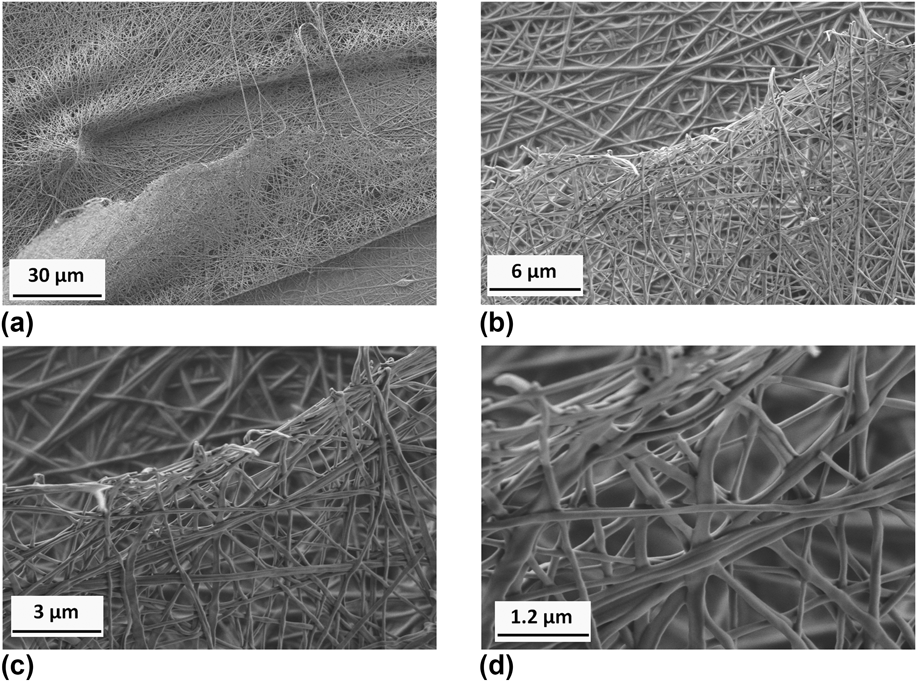
The optimized process parameters that led to stable ES for over 6 h were as follows: precursor viscosity: 390 cP, WD: 14.5 cm, voltage: 26 kV, precursor feed rate: 0.6 mL/h and RH of 35–40%. These parameters allowed collection of over 90 wt% of theoretical fibrous product. The collection efficiency was determined by weighing the dried green mats removed from the collector and comparing this value with the expected one based on the assay of the injected precursor. The morphology of the resulting green electrospun fibers with diameters in the 80–180 nm range is shown in Fig. 2.
HRSEM images of green K-doped Fe–Al-nitrates/PVA fibers taken at different magnifications: (a) x2000 (b) x10,000 (c) x20,000 and (d) x50,000.
Converting the green mats into oxide fibers requires determination of an optimal temperature profile of the organic burnout and sintering steps. Thermal analysis of the “green” Fe(NO3)3/Al(NO3)3 hydrates/KOH/PVA mat in air showed a small endothermic effect in the range from room temperature (RT) to 150 °C, followed by a sharp exothermic peak and ∼20% weight loss [Fig. 3(a)]. The gaseous products detected by MS at this stage included mainly NO, N2O, NO2, CO2 and H2O [Fig. 3(b)]. We attribute the small endotherm at 96 °C to nitrate-hydrates melting which triggered a fast PVA oxidation by highly mobile nitrate ions, explaining the release of NOx, CO2 and H2O. The next stages of polymer oxidative decomposition started at ∼150 °C involves external oxidant (O2) from air. Oxygen intense uptake by these reactions is evident from the shallow “dips” in the oxygen MS signal [Fig. 3(b)]. These stages included decomposition, internal and external gradual oxidation, accompanied by H2O, NOx, CO2 and –CH3 signals and a total weight loss of 70% at 415 °C.
(a) TGA–DTA and (b) TG-MS of green nitrates/PVA fibers.
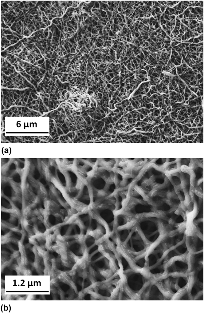
Based on the above decomposition patterns [Fig. 3(a)] thermal treatment profile in air was adapted. Four 30 min heating stages between RT and 250 °C with heating rates of 60 °C/h in between prevented the sharp decomposition and massive gas release. However, the low hydrates melting temperature can lead to the following negative effects: Firstly, large quantities of melts could dissolve the nanofibers and destroy the mat fibrous morphology. Secondly, the melting is coupled with internal strong exothermic oxidation, which may cause local overheating further accelerating oxidative degradation which may harm the fiber structure. To prevent these two negative processes, the fibers were slowly heated at 2 °C/min from RT to 100 °C and kept at this temperature 0.5 h. The soak at 450 °C, where the organics were fully burned out, allowed the Fe-oxide crystallization and sintering of very small crystallites into mechanically stable fibers. The morphology of the resulting white fibers is shown in Figs. 4(a) and 4(b). It can be seen that the fibrous morphology was preserved during this heating profile, with the diameter of fibers in final “white” mats ranging from 140 to 280 nm and their surface is relatively smooth with SSA of ∼98 m2/g. We believe that the smooth surface of fibers with lack of visible by HRSEM internal mesoporosity is due to the melting of nitrate-hydrates described above.
HRSEM images of white K-doped Fe–Al–O fibers prepared from nitrates solution taken at different magnifications: (a) x10,000 and (b) x50,000.
B. Precursor based on organic solution of Fe–Al AcAcs
To decrease undesired high conductivity of the precursor liquid and eliminate oxidative degradation of polymer by nitrates, Fe and Al acatylacetonates in ethanol and PVP were used as main precursor components. AA was added to these precursors to increase the Fe(acac)3 solubility, buffer the KOH and serve as a surfactant, in place of Triton X-100 used in the nitrates case. The precursor viscosity was 900–1000 cP throughout the whole process.
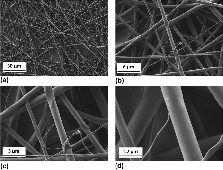
The parameters for stable ES over 6 h were as follows: WD: 14.5 cm, voltage: 18 kV, precursor feed rate: 0.9 mL/h and RH of 35–40%. These parameters allowed collection of over 90 wt% of theoretical fibrous material. Collection efficiency was determined as described earlier. It was observed that an increase in voltage up to 27 kV at 0.9 mL/h feed rate did not affect the fibers morphology. Above this voltage the losses increased due to stray fiber deposition. On the other hand, feed rates could be increased up to 1.65 mL/h with simultaneous voltage increase up to 26 kV without significant negative effects on fibers morphology and yield. Above a feed rate of 1.65 mL/h the morphology of fibers began deteriorating. The morphology of green fibers prepared from AcAcs precursor is shown in Fig. 5. The green fibers diameters distribution is clearly bimodal with large and small diameters in the 500–1000 and 100–200 nm ranges, respectively. This phenomenon is related to the electric field during ES and can be avoided if desired through adjustment of the precursor viscosity as seen recently in lead zirconium titanate (PZT) fibers.Reference Gevorkyan, Shter, Shmueli, Buk, Meir and Grader31
HRSEM images of green K-doped AcAcs/PVP fibers taken at different magnifications: (a) x2000 (b) x10,000 (c) x20,000 and (d) x50,000.
Thermal analysis of green Fe(acac)3/Al(acac)3/KOH/AA/PVP fiber mats in air showed a complex multistage oxidative degradation [Fig. 6(a)]. In the first stage (RT–120 °C), weight loss of 11% accompanied with an endothermic effect was observed. It was attributed to physically adsorbed water and CO2 release, confirmed by MS signals m/z = 18 and m/z = 44 [Fig. 6(b)]. Several exothermic events occur between 145 and 355 °C with an overall weight loss of 36%. Finally, the strongest exothermic effect with 48.4% weight loss occurred in the 355–460 °C range. The total weight loss during heating from RT to 460 °C was 95.7%, reflecting the large content of organic species.
(a) TGA–DTA and (b) TG-MS of green AcAcs/PVP fibers.
Based on mass spectra of the evolved gases, the exothermic stages above 145 °C can be attributed to oxidative decomposition of iron and aluminum AcAcs (m/z = 15, 39, 41, 43, 58) and PVP (m/z = 30), along with massive CO2 and water release. Interestingly, H2 signal (m/z = 2) appeared on the mass spectrogram in the last decomposition stage, between 400 and 440 °C. We propose the water–gas shift reaction [Eq. (1)] which is responsible for his phenomenon:
 $${{\rm{CO}}\, + \,{{\rm{H}}_{\rm{2}}}{\rm{O}}\,{\rm{ ⇌ }}\,{\rm{C}}{{\rm{O}}_{\rm{2}}}\, + \,{{\rm{H}}_2}\,\,\,.$$
At temperatures above 400 °C the iron oxide crystalline phase is already formed and can catalyze this reaction, consuming CO and water from an incomplete organics burnout. It should be noted that CO signal is not detectable with air as a carrier gas due to N2.
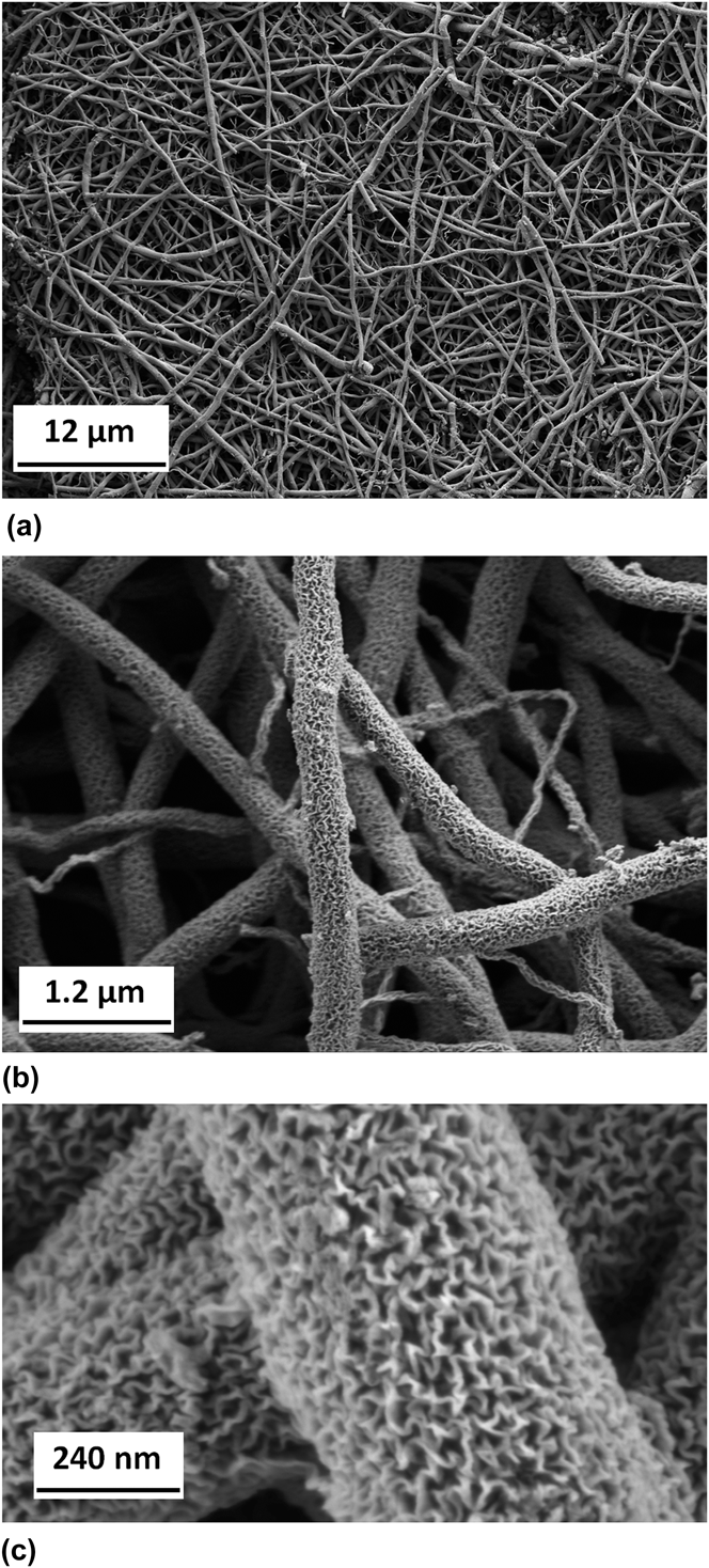
Based on the thermal analysis data, a heat treatment profile in air included three 60 min burnout steps up to 360 °C with heating rates of 40 °C/h followed by sintering at 475 °C for 60 min. This treatment resulted in fibrous structured ceramic mats with fibers diameters mainly of 300–400 nm and few fibers with lower diameter of 80–120 nm (Fig. 7). The apparent shrinkage of “green” to “white” fibers was ∼40–60% in diameter for thicker fibers. It is remarkable that the fiber morphology was maintained even after ∼96% loss of the initial fiber weight. The highly meso-porous structure of the sintered nanofibers was found to have a SSA of ∼93 m2/g. The large SSA obtained in both nitrate and AcAc fibers are very similar, which translates to equivalent spherical particles that are ∼10 nm in diameter in both cases. This means that the contribution of the mesopores observed in the AcAc fibers in Fig. 7 to the overall SSA is not large. However the micropores in the AcAc fibers are more accessible to heterogeneous gas–solid reactions due to the open mesopores in them. Hence the textured AcAc fibers are to be expected to display enhanced catalytic performance, compared to the smooth nitrate fibers.
HRSEM images of white K-doped Fe–Al–O fibers prepared from AcAcs solution taken at diffesrent magnifications: (a) x5000 (b) x50,000 and (c) x250,000.
The formation of this mesoporous structure may be explained by several possible mechanisms. The large stretching of the fibers during the spinning process aligns the polymer component within the green fiber. The stretched polymer can relax during heating, giving rise to a remarkable linear shrinkage of roughly 40–50%. One possible porosity mechanism may be related to the fibers shrinkage, where during the heating stage, the shrinkage induces the formation of “wrinkles” as the highly stretched fiber shrinks. By this mechanism the fibers meso-porosity can be controlled by varying the heating rates and thus controlling the rates of shrinkage and mass loss. The second mechanism may be related to possible local boiling of Al(acac)3, creating bubbles which are responsible for the formation of meso-porosity. In this case, the extent of the effect can be controlled by heating rate at the appropriate stage. Understanding the basic underlying mechanism of porosity evolution in these fibers is of major importance for porous material design in general and for catalyst design in particular but is beyond the scope of this paper.
Following the heat treatment at 450 and 475 °C both nitrates and AcAcs derived “white” fibers became crystalline with a magnetite-like phase, as evident from the XRD patterns in Fig. 8. No separate crystalline aluminum oxide phase was found in these patterns, suggesting that either aluminum is amorphous or that aluminum is incorporated into the magnetite-like spinel structure of iron oxide, for example by substituting for some of the Fe3+ ions.
XRD patterns of “white” fibers derived from aqueous nitrate precursor (black) and organic AcAc solutions (green).
Comparison of the two aforementioned preparation routes reveals several advantages of the metal AcAcs precursor solutions over the nitrates analog. Precursor stability over time in terms of viscosity and a wider operating parameter range (i.e., feed rate and voltage) was possible with the AcAcs. Moreover, the fibers throughput was higher for ES of AcAcs precursors by almost a factor of three. Most importantly, the morphology of “white” K/Fe–Al–O fibers obtained by this route is characterized by a highly meso-porous surface structure with large SSA. The open morphology coupled with large SSA is crucial for application in heterogeneous catalysis. In summary, the route of AcAcs precursors described herein provides an excellent platform for meso- and macroporous structured nanofibers that can potentially serve as state-of-the-art future catalysts.
IV. CONCLUSIONS
This paper presents the synthesis of K-promoted Fe–Al–O ceramic fibers by ES of two types of precursor solutions: an aqueous solution of nitrate salts, and an organic solution of metal-organic complexes. The potassium was added as KOH while PVA and PVP were used as the polymers in the aqueous and organic solutions, respectively. The aqueous nitrate precursors were found to be less stable due to gradual in situ oxidation of the PVA, which led to a viscosity decrease and hence unstable ES. On the other hand, in metal AcAcs organic precursor solutions the precursor viscosity was constant during at least 100 h.
Based on thermal analysis of the “green” fiber mats, heat treatment profiles were devised to provide optimal organic burnout and densification, preserving the fiber structure in final ceramic mats. The two precursor solutions resulted in two distinct fibers morphologies: The aqueous nitrate system gave rise to smooth and dense fibers, 140–280 nm in diameters. We believe the smooth structure of the nitrate-based fibers is due to melting and apparent local restructuring of the fibers during the fiber thermal treatment. The AcAcs organic system led to thicker fibers mainly in the 300–400 nm range, and to an open mesoporous structure. The large SSA of 98 and 93 m2/g obtained in both nitrate and AcAc fibers is very similar. This means that the contribution of the mesopores observed in the AcAc fibers to the overall SSA is not large. However the micropores in the AcAc fibers are more accessible to heterogeneous gas–solid reactions due to the open mesopores. Hence the textured AcAc fibers are to be expected to display enhanced catalytic performance, compared to the smooth nitrate fibers.
The fiber meso-porosity is highly desirable for efficient transport of potential reagents to active sites on the internal fiber surface. Testing of the catalytic performance of these fibers is currently underway. We believe that fiber mats of the nano-composite K-doped Fe–Al–O spinel catalyst have the potential to improve the heterogeneous CO2 hydrogenation, however this generic structure is highly promising for other catalytic applications.
ACKNOWLEDGMENTS
Supported by the I-CORE Program of the Planning and Budgeting Committee and The Israel Science Foundation (Grant No. 152/11), Israel Ministry of Infrastructures, Energy and Water (Grant No. 880002) and by joint grant of the Council for Higher Education and by the Center for Absorption in Science (Israel) under the KAMEA program. Authors acknowledge the support of the RBNI, the Adelis Foundation and the Grand Technion Energy Program (GTEP) and the Arturo Gruenbaum Chair in Material Engineering.