1. INTRODUCTION
As the demand for quick reaction and poor environment survivability capability in on board systems grows higher, the in-motion alignment algorithm for vehicle-carried Strapdown Inertial Navigation Systems (SINS) has become the focus of much research (Ali and Ushaq, Reference Ali and Ushaq2009; Jalving et al., Reference Jalving, Gade, Svartveit, Willumsen and Sqrhagen2004; Yang et al., Reference Yang, Peng, Wang and Zhou2013; Zhang et al., Reference Zhang, Huang, Wu and Li2014). In order to align an in-motion vehicle-carried SINS, it needs to be provided with auxiliary information (e.g., position, velocity and so on) by an external navigation device such as camera, electronic map, Global Positioning System (GPS), Odometer (OD), etc (Yang et al., Reference Yang, Peng, Wang and Zhou2013; Han and Wang, Reference Han and Wang2010; Yan and Qin, Reference Yan and Qin2007; Wang et al., Reference Wang, Yang, Yu and Lei2013). A camera has the advantages of small size and low cost, but the use of a camera requires higher knowledge of the external environment. Electronic map-aided in-motion alignment has the advantages of high precision and simple algorithm design. However, the high accuracy of the electronic map takes up too much memory, resulting in poor real-time alignment. Compared to the electronic map and camera, GPS is the most useful aiding sensor, which could provide geodetic frame velocity and Earth frame position, but the GPS signal is susceptible to interference and is not reliable in war and other hostile environments (Hong et al., Reference Hong, Han, Lee and Paik2010; Zhao et al., Reference Zhao, Zhao, Guo, Wang, Zhou and Wang2015). In contrast to GPS, OD aided in-motion alignment is widely adopted owing to its fully self-contained characteristics, but the output velocity of the OD is in the body frame. In summary, it is a difficult problem to align an in-motion vehicle-carried SINS without GPS and developing an OD aided in-motion alignment algorithm is very necessary.
The traditional initial alignment is often divided into two procedures: coarse alignment and fine alignment (Silson, Reference Silson2011; Wu et al., Reference Wu, Wu, Hu and Hu2011; Godha and Cannon, Reference Godha and Cannon2007). The coarse alignment is used to rapidly resolve large misalignment angles and then the fine alignment is used to compensate and correct the misalignment angle further (Pei et al., Reference Pei, Zhu and Zhao2015). The alignment described in this paper refers to both the coarse alignment and fine alignment.
A lot of literature has been devoted to coarse alignment methods. The conventional coarse alignment based on the analytical method generally uses two feature vectors of the Earth: the acceleration of gravity and the angular rate of the Earth's rotation, and it requires the vehicle to be initially static (Fang and Wan, Reference Fang and Wan1996; Xiong et al., Reference Xiong, Guo and Yang2014; Chang, Reference Chang2015). While in the motion condition, the angular rate is much larger than the Earth's rotation, the attitude error is large in most situations and the alignment would take a long time so the conventional coarse alignment method cannot be utilised. Another type of algorithm applies the velocity from GPS as an input and an optimisation approach is used (Silson, Reference Silson2011; Wu and Pan, Reference Wu and Pan2013; Chang et al., Reference Chang, Li and Chen2015). This method could offer a good result for the fine alignment in the in-motion condition. However, it does not apply to the in-motion alignment method aided by OD. The reason is that the output velocity of GPS is in the navigation frame, but the output velocity of OD is in the body frame. In the fine alignment procedure, a linear Kalman Filter (KF) is generally used in the fine alignment based on equations of small misalignment angles (Zhao et al., Reference Zhao, Zhao, Guo, Wang, Zhou and Wang2015; Chang, Reference Chang2015; Veremeenko and Savel'ev, Reference Veremeenko and Savel'ev2013; Li et al., Reference Li, Pan, Wang, Jiang and Deng2015; Wang, Reference Wang2009). An in-motion fine alignment error model was developed by Zhao et al. (Reference Zhao, Zhao, Guo, Wang, Zhou and Wang2015) in which the position increment differences between SINS and OD along the navigation frame were considered as measurements, and a KF was used to estimate the error angle. In this method, the coefficients of installation angle error are the output velocity increment of OD. If an OD fault occurs, the measurement matrix will change and the alignment accuracy will reduce.
In this paper, a novel in-motion alignment algorithm for vehicle-carried SINS based on OD aiding is developed, and it is a complete in-motion alignment method. Firstly, like Silson (Reference Silson2011) and Wu and Pan (Reference Wu and Pan2013), we utilise the attitude optimisation method to realise the in-motion coarse alignment. The difference is that the velocity update equation in the body frame has been formulated. This is the first contribution of this paper. Secondly, the in-motion fine alignment algorithm aided by OD based on KF is formulated, in which a new measurement equation in the body frame is established. This is the second contribution of this paper since it can also be suitable for the in-motion alignment method aided by motion constraints of the vehicle (Godha and Cannon, Reference Godha and Cannon2007; Dissanayake et al., Reference Dissanayake, Sukkarieh and Nebot2001; Fu et al., Reference Fu, Qin, Li and Wang2012) which has not been fully explored before. Finally, simulation and experiments are carried out to illustrate the application and usefulness of the proposed method.
2. IN-MOTION COARSE ALIGNMENT ALGORITHM BASED ON ATTITUDE OPTIMISATION
2.1. Coordinate Frame Definitions
To better understand SINS initial alignment, it is necessary to explain the navigation coordinate system. The coordinate frames used for the SINS initial alignment are defined as follows.
-
(i) The e frame is the Earth-fixed coordinate frame. The e z axis is parallel to the Earth's rotation axis and the e x axis is in the equatorial plane and points to the meridian of the body initial position. The e y axis completes the right-handed coordinate system.
-
(ii) The i frame is the inertial coordinate frame. It is formed by fixing the e frame at the beginning of the coarse alignment in the inertial space.
-
(iii) The n frame is the true navigation coordinate frame which is the local level coordinate frame. The n x axis points to the East, the n y axis points to the North, and the n z axis points to the zenith.
-
(iv) The n′ frame is the computed navigation coordinate frame. There is some error between the n frame and the n′ frame owing to the alignment error and the sensor error.
-
(v) The m frame is the vehicle body coordinate frame. The x m axis is parallel to the body lateral axis and points to the right. The y m axis is parallel to the body longitudinal axis and points forward. The z m axis is parallel to the body vertical axis and points upward. In the general case, assume the OD body coordinate frame with the m frame overlap.
-
(vi) The b frame is the strapdown inertial sensor's body coordinate frame.
2.2. The Principle of the In-motion Coarse Alignment Algorithm Based on Attitude Optimisation
For SINS, the initial alignment is implemented to obtain the coordinate transformation matrix from the b frame to the n frame. The common navigation (attitude and velocity) update equations are written in the n frame as (Wang et al., Reference Wang, Yang, Yu and Lei2013; Wu et al., Reference Wu, Wu, Hu and Hu2011; Li et al., Reference Li, Xu, Chang and Zha2014)
 $$\dot{{\bi {C}}}_b^{\, n}={{\bi {C}}}^{\, n}_b{{\bi \omega}}_{nb}^b\times $$
 $$\dot{{\bi {V}}}^{\, n}_{en}={{\bi {C}}}^{\, n}_b {{\bi {f}}}^b-\lpar 2{{\bi \omega}}_{ie}^n+{{\bi \omega}}_{en}^n\rpar \times{{\bi {V}}}^{n}_{en}+{{\bi {g}}}^n $$
where
 ${{\bi {C}}}^{\, n}_{b}$
denotes the attitude matrix from the b frame to the n frame,
 ${\bi {V}}^{\, n}_{en}$
is the ground velocity,
 ${{\bi {f}}}^{b}$
is the special force measured by the accelerometers in the b frame,
 ${{\bi \omega}}^{n}_{ie}$
is the angular rate of the Earth's rotation in the n frame,
 ${{\bi \omega}}^{n}_{en}$
is the angular rate of the n frame with respect to the e frame, expressed in the n frame,
 ${{\bi {g}}}^{n}$
is gravity in the n frame,
 $\lpar \bullet\rpar \times$
is the matrix form of a cross-product which satisfies
 ${{\bi {a}}}\times {{\bi {b}}}=\lpar {{\bi {a}}}\times\rpar {{\bi {b}}}$
,
 ${{\bi \omega}}^{b}_{nb}$
is the angular rate of the b frame with respect to the n frame and can be described as
 $${{\bi \omega}}^b_{nb}={{\bi \omega}}^b_{ib}-{{\bi \omega}}^b_{in}= {\bi \omega}^b_{ib}-{\bi C}^b_{n}\lpar {\bi \omega}^n_{ie}+{\bi \omega}^n_{en}\rpar $$
where
 ${{\bi \omega}}^{b}_{ib}$
is the angular rate measured by the gyroscopes in the b frame.
Equation (1) is the traditional attitude update equation. By the chain rule, the attitude matrix can be decomposed into three parts at any time, that is
 $${{\bi {C}}}^{\, n}_b\lpar t\rpar ={{\bi {C}}}^{\, n\lpar t\rpar }_{n\lpar 0\rpar }{{\bi {C}}}^{\, n}_b\lpar 0\rpar {\bi {C}}^{b\lpar 0\rpar }_{b\lpar t\rpar } $$
where n(0) and b(0) denote the inertial non-rotating frame, which is formed by fixing the n frame and b frame at the start-up in the inertial space, respectively.
 ${{\bi {C}}}^{\, b\lpar t\rpar }_{b\lpar 0\rpar }$
and
 ${{\bi {C}}}^{\, n\lpar t\rpar }_{n\lpar 0\rpar }$
, respectively, encode the attitude changes of the b frame and n frame from time 0 to t and can be determined by
 $$\dot{{\bi {C}}}_{\, b\lpar t\rpar }^{\, b\lpar 0\rpar }={{\bi {C}}}_{\, b\lpar t\rpar }^{\, b\lpar 0\rpar } {{\bi \omega}}^{b}_{ib}\times $$
 $$\dot{{\bi {C}}}_{\, b\lpar t\rpar }^{\, n\lpar 0\rpar }={{\bi {C}}}_{\, n\lpar t\rpar }^{n\lpar 0\rpar } {{\bi \omega}}^{n}_{in}\times $$
where
 ${{\bi \omega}}^{n}_{in}$
is the angular rate of the n frame with respect to the i frame and
 ${{\bi \omega}}^{n}_{in}={{\bi \omega}}^{n}_{ie}+{{\bi \omega}}^{n}_{en}\approx {{\bi \omega}}^{n}_{ie}$
for the reason that
 ${{\bi \omega}}^{n}_{en}$
is unknown but can be omitted due to the fact that the vehicle does not move at a very high speed and it is the coarse alignment stage. In addition, it can be easily observed that the initial conditions for the differential equation in Equations (5) and (6) are both identity matrices. Therefore,
 ${{\bi {C}}}_{\, b\lpar t\rpar }^{\, b\lpar 0\rpar }$
and
 ${{\bi {C}}}_{\, n\lpar t\rpar }^{\, n\lpar 0\rpar }$
can be easily obtained based on well-known attitude update methods. In this respect, the initial alignment has been transformed into determining the constant matrix
 ${{\bi {C}}}^{\, n}_{b}\lpar 0\rpar $
based on the decomposition of Equation (4).
As the output of OD is the velocity in the b frame, we must convert Equation (2) into the b frame. For this, Equation (2) can be rewritten as
 $$\dot{{\bi {V}}}_{en}^{\, n}=\displaystyle{{d\lpar {\bi {C}}_b^{\, n}{\bi {V}}_{en}^{\, b}\rpar }\over{dt}} = \dot{{\bi {C}}}_b^{\, n}{\bi {V}}_{en}^{\, b}+{\bi {C}}^{\, n}_b \dot{{\bi {V}}}_{en}^{\, b}={\bi {C}}_b^{\, n}{\bi {f}}^b -\lpar 2{\bi \omega}^{n}_{ie}+{\bi \omega}^{n}_{en}\rpar \times {\bi {V}}_{en}^{\, n}+ {\bi {g}}^n $$
Substituting Equations (1) and (4) into Equation (7) and multiplying both sides from left by
 ${\bi {C}}_{n\lpar t\rpar }^{\, n\lpar 0\rpar }$
yields
 $${\bi {C}}_b^{\, n}\lpar 0\rpar {\bi {C}}_{\, b\lpar t\rpar }^{\, b\lpar 0\rpar } {\bi \omega}^{b}_{nb}\times {\bi {V}}^{\, b}_{en}\, {+}\, {\bi {C}}_b^{\, n}\lpar 0\rpar {\bi {C}}_{b\lpar t\rpar }^{\, b\lpar 0\rpar } \dot{{\bi {V}}}^{b}_{en}={\bi {C}}_b^{\, n}\lpar 0\rpar {\bi {C}}_{\, b\lpar t\rpar }^{\, b\lpar 0\rpar }{\bi {f}}^b- {\bi {C}}_{\, n\lpar t\rpar }^{\, n\lpar 0\rpar }\lpar 2{\bi \omega}^{n}_{ie}\, {+}\, {\bi \omega}^{n}_{en}\rpar \times {\bi {V}}^{\, n}_{en}\, {+}\, {\bi {C}}_{\, n\lpar t\rpar }^{\, n\lpar 0\rpar }{\bi {g}}^n $$
Or equivalently
 $${\bi {C}}_b^{\, n}\lpar 0\rpar \lpar {\bi {C}}_{\, b\lpar t\rpar }^{\, b\lpar 0\rpar }{\bi \omega}^{n}_{nb}\times {\bi {V}}^{\, b}_{en}+ {\bi {C}}_{b\lpar t\rpar }^{\, b\lpar 0\rpar } \dot{{\bi {V}}}_{en}^{b} - C_{b\lpar t\rpar }^{b\lpar 0\rpar } {\bi {f}}^b\rpar =-{\bi {C}}_{\, n\lpar t\rpar }^{\, n\lpar 0\rpar } \lpar 2{\bi \omega}^{n}_{ie}+{\bi \omega}^{n}_{en}\rpar \times {\bi {V}}^{\, n}_{en}+{\bi {C}}_{\, n\lpar t\rpar }^{\, n\lpar 0\rpar }{\bi {g}}^n $$
As is known, the output of OD is the incremental position in the b frame, the outputs of gyroscope and accelerometer are the incremental angle and incremental velocity, respectively. The integral forms are needed, integrating Equation (9) on both sides
 $${\bi {C}}_b^{\, n}\lpar 0\rpar {\bi \alpha}_v\lpar t\rpar ={\bi \beta}_v\lpar t\rpar $$
where
 $$\left\{\matrix{{\bi \alpha}_v\lpar t\rpar =\vint_0^t \lpar {\bi {C}}_{\, b\lpar t\rpar }^{\, b\lpar 0\rpar }{\bi \omega}_{nb}\times {\bi {V}}^{\, b}_{en}+ {\bi {C}}_{b\lpar t\rpar }^{\, b\lpar 0\rpar }{\bi {f}}^b\rpar dt \hfill \cr {\bi \beta}_v\lpar t\rpar =\vint_0^b \lpar -{\bi {C}}_{\, n\lpar t\rpar }^{n\lpar 0\rpar } \lpar 2{\bi \omega}^{n}_{ie}+{\bi \omega}^{n}_{en}\rpar \times {\bi {V}}^{\, n}_{en}+{\bi {C}}^{\, n\lpar t\rpar }_{n\lpar 0\rpar }{\bi {g}}^n\rpar dt \hfill \cr }\right.$$
In this respect, the initial attitude matrix
 ${\bi {C}}_{b}^{\, n}\lpar 0\rpar $
can be uniquely solved by the attitude optimisation method described in Wahba (Reference Wahba1965), Shuster and Oh (Reference Shuster and Oh1981) and Bar-Itzhack (Reference Bar-Itzhack1996) to minimise
 $$L\lpar {\bi {C}}_b^{\, n}\lpar 0\rpar \rpar =\sum\lpar {\bi {C}}_b^{\, n}\lpar 0\rpar {\bi \alpha}_v\lpar t\rpar -{\bi \beta}_v\lpar t\rpar \rpar ^2 $$
The key of initial alignment is how to calculate
 ${\bi \alpha}_{v}\lpar t\rpar $
and
 ${\bi \beta}_{v}\lpar t\rpar $
with different integral time.
2.3. The Calculation of α v (t) and β v (t).
For Equation (11), the first and second integral in
 ${\bi \alpha}_{v}\lpar t\rpar $
can be rewritten as
 $$\eqalign{&\vint_0^t \lpar {\bi {C}}_{\, b\lpar t\rpar }^{b\lpar 0\rpar }{\bi \omega}^{b}_{nb}\times {\bi {V}}^{\, b}_{en}+ {\bi {C}}_{b\lpar t\rpar }^{\, b\lpar 0\rpar } \dot{{\bi {V}}}_{en}^{\, b}\rpar dt= {\bi {C}}_{b\lpar t\rpar }^{\, b\lpar 0\rpar }{\bi {V}}_{en}^{\, b}\vert _{0}^{t}+ \vint_0^t\lpar {\bi {C}}^{\, b\lpar t\rpar }_{b\lpar 0\rpar }{\bi \omega}^{b}_{nb}\times {\bi {V}}^{\, b}_{en}+ \dot{{\bi {C}}}_{b\lpar t\rpar }^{b\lpar 0\rpar }\dot{{\bi {V}}}_{en}^{\, b}\rpar dt \cr & \quad = {\bi {C}}_{b\lpar t\rpar }^{\, b\lpar 0\rpar } {\bi {V}}_{en}^{\, b}\vert _{0}^{t}+\vint_0^t\lpar {\bi {C}}_{\, b\lpar t\rpar }^{b\lpar 0\rpar } \lpar {\bi \omega}^{b}_{ib}- {\bi \omega}^{b}_{in}\rpar \times {\bi {V}}_{en}^{\, b}-{\bi {C}}_{\, b\lpar t\rpar }^{b\lpar 0\rpar } {\bi \omega}^{n}_{ib}\times {\bi {V}}^{\, b}_{en}\rpar dt \cr & \quad = {\bi {C}}_{b\lpar t\rpar }^{\, b\lpar 0\rpar }{\bi {V}}_{en}^{\, b}\vert _{0}^{t} + \vint_0^t \lpar {\bi {C}}_{\, b\lpar t\rpar }^{b\lpar 0\rpar }\lpar {\bi \omega}^{b}_{ie}- {\bi \omega}^{b}_{en}\rpar \times {\bi {V}}_{en}^{\, b}\rpar dt} $$
Notice that before the initial alignment is finished
 ${\bi {C}}_{b}^{\, n}\lpar t\rpar $
is unknown and
 ${\bi \omega}^{b}_{ie}$
is unknown too. However, due to ω
ie
being a very small value and the fact that the vehicle does not move at a very high speed (at about 100 Km/h),
 $\lpar {\bi \omega}^{b}_{ie}+ {\bi \omega}^{b}_{en}\rpar \times {\bi {V}}_{en}^{\, b}$
would be small too. e.g., when
 ${\bi {V}}_{en}^{\, b}=120\, \hbox{Km}/\hbox{h}$
, the highest values in
 ${\bi \omega}^{b}_{ie}\times {\bi {V}}^{\, b}_{en}$
and
 ${\bi \omega}^{b}_{en}\times {\bi {V}}^{\, b}_{en}$
are
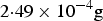 $2{\cdot}49 \times 10^{-4} \hbox{g}$
and
 $0{\cdot}89\times 10^{-4}\, \hbox{g}$
, respectively. This is the same as the bias of a medium accuracy accelerometer, so the second integral part in
 ${\bi \alpha}_{v}\lpar t\rpar $
can be omitted in the coarse alignment stage and we can approximate this part by
 $$\vint_0^t \lpar {\bi {C}}_{\, b\lpar t\rpar }^{b\lpar 0\rpar }{\bi \omega}^{b}_{nb}\times {\bi {V}}^{\, b}_{en}+ {\bi {C}}_{b\lpar t\rpar }^{\, b\lpar 0\rpar } \dot{{\bi {V}}}_{en}^{\, b}\rpar dt\approx {\bi {C}}_{\, b\lpar t\rpar }^{b\lpar 0\rpar }{\bi {V}}^{\, b}_{en}\lpar t\rpar - {\bi {V}}^{\, b}_{en} \lpar 0\rpar $$
The calculation methods for the third part of
 ${\bi \alpha}_{v}\lpar t\rpar $
had been already expressed in Wu and Pan (Reference Wu and Pan2013) as
 $$\eqalign{&\vint_0^t {\bi {C}}_{\, b\lpar t\rpar }^{b\lpar 0\rpar } {\bi {f}}^b dt=\sum_{k=0}^{N-1} {\bi {C}}_{b\lpar t_k\rpar }^{b\lpar 0\rpar }\vint_{t_k}^{t_{k+1}}{\bi {C}}^{b\lpar t_k\rpar }_{b\lpar t\rpar }{\bi {f}}^b dt\approx \sum_{k=0}^{N-1} {\bi {C}}^{b\lpar 0\rpar }_{b\lpar t_k\rpar }\vint^{t_{k+1}}_{t_k}\left({\bi {I}}+\left(\vint_{t_k}^t\lpar {\bi \omega}^{b}_{ib}\times\rpar d\tau\right)\right){\bi {f}}^b dt \cr & \quad =\sum_{k=0}^{N-1}{\bi {C}}_{b\lpar t_k\rpar }^{b\lpar 0\rpar }\left[\Delta {\bi {V}}_1+ \Delta {\bi {V}}_2+\displaystyle{{1} \over {2}}\lpar \Delta {\bi \theta}_1+\Delta {\bi \theta}_2\rpar \times \lpar \Delta {\bi {V}}_1+ \Delta {\bi {V}}_2\rpar \right. \cr & \qquad\qquad\qquad \left. +\displaystyle{{2}\over {3}}\lpar \Delta {\bi \theta}_1\times \Delta {\bi {V}}_2+\Delta {\bi {V}}_1\times \Delta {\bi \theta}_2\rpar \right]} $$
where
 $\Delta {\bi {V}}_{1}$
,
 $\Delta {\bi {V}}_{2}$
are the first and second samples of the accelerometer-measured incremental velocity and
 $\Delta {\bi \theta}_{1}$
,
 $\Delta {\bi \theta}_{2}$
are the first and second samples of the gyroscope-measured incremental angle, respectively. So
 ${\bi \alpha}_{v}\lpar t\rpar $
can be approximated as
 $$\eqalign{{\bi \alpha}_v\lpar {\bi {t}}_N\rpar & ={\bi {C}}^{b\lpar 0\rpar }_{b\lpar t_N\rpar }{\bi {V}}_{en}^{\, b} \lpar t_N\rpar -{\bi {V}}^{\, b}_{en} \lpar 0\rpar \cr & \quad -\sum_{k=0}^{N-1}{\bi {C}}_{b\lpar t_k\rpar }^{b\lpar 0\rpar }\left[\Delta {\bi {V}}_1+ \Delta {\bi {V}}_2+\displaystyle{{1}\over{2}}\lpar \Delta {\bi \theta}_1+\Delta {\bi \theta}_2\rpar \times \lpar \Delta {\bi {V}}_1+ \Delta {\bi {V}}_2\rpar \right. \cr & \qquad\qquad \qquad \left. +\displaystyle{{2}\over {3}}\lpar \Delta {\bi \theta}_1\times \Delta {\bi {V}}_2+\Delta {\bi {V}}_1\times \Delta {\bi \theta}_2\rpar \right]} $$
For the first integral part in
 ${\bi \beta}_{v}\lpar t\rpar $
, since the output velocity of the OD is in the b frame, not in the n frame, so
 ${\bi {V}}^{\, n}_{en}$
is unknown. However,
 ${\bi \omega}^{n}_{ie}\times {\bi {V}}^{\, n}_{en}$
and
 ${\bi \omega}^{n}_{ie}\times {\bi {V}}^{\, n}_{en}$
could also be omitted for the same reason as the vehicle would not move at a very high speed and ω
ie
is a very small value. Therefore,
 ${\bi \beta}_{v}\lpar t\rpar $
can be approximated as
 $$\eqalign{{\bi \beta}_v\lpar t_N\rpar &\approx \vint_0^{t_N} {\bi {C}}_{\, n\lpar t\rpar }^{n\lpar 0\rpar } {\bi {g}}^n dt= \sum_{k=0}^{N-1} {\bi {C}}_{n\lpar t_k\rpar }^{n\lpar 0\rpar }\vint_{t_k}^{t_{k+1}}{\bi {C}}^{n\lpar t_k\rpar }_{n\lpar t\rpar }{\bi {g}}^n dt \cr & \quad \approx \sum_{k=0}^{N-1} {\bi {C}}_{n\lpar t_k\rpar }^{n\lpar 0\rpar }\vint_{t_k}^{t_{k+1}} \lpar {\bi {I}}+\lpar t-t_k\rpar {\bi \omega}^{b}_{ib}\times\rpar {\bi {g}}^n dt \cr & \quad =\sum_{k=0}^{N-1} {\bi {C}}_{n\lpar t_k\rpar }^{n\lpar 0\rpar }\vint_{t_k}^{t_{k+1}}\left(T{\bi {I}}+\displaystyle{{T^2}\over{2}} {\bi \omega}^{n}_{in}\times\right){\bi {g}}^n dt \approx \sum_{k=0}^{N-1} {\bi {C}}_{n\lpar t_k\rpar }^{n\lpar 0\rpar } \vint_{t_k}^{t_{k+1}}\left(T{\bi {I}}+\displaystyle{{T^2}\over{2}} {\bi \omega}^{n}_{ie}\times\right){\bi {g}}^n dt} $$
where
I
is the identity matrix. T is the time duration of the update interval
 $\lsqb t_{k}\quad t_{k+1}\rsqb $
,
 $k=0\comma \; 1\comma \; 2\comma \; \ldots\comma \; N-1$
and t
k
= kT.
3. IN-MOTION FINE ALIGNMENT ALGORITHM BASED ON KF
The coarse initial attitude angle can be obtained by the coarse alignment method in Section 2. The carrier heading angle error is estimated to within a few degrees and pitch/roll angle to within a few tenths of a degree. In this section, the in-motion fine alignment algorithm based on KF is developed.
3.1. SINS/OD Error Model
3.1.1. The effect of OD scale factor error and SINS installation angle error
In ideal conditions, while the vehicles travel close to the ground without skidding or jumping, the speed of vehicle in the x m and z m direction is zero (Dissanayake et al., Reference Dissanayake, Sukkarieh and Nebot2001; Fu et al., Reference Fu, Qin, Li and Wang2012), and the output of the OD is the position increment of the vehicle in the y m direction, i.e.,
 $${\bi {S}}^m_{OD}=\lsqb \matrix{0 & S_{OD}& 0 \cr}\rsqb ^{\rm T} $$
where S OD is the ideal output of the OD.
In practice, due to the influence of the OD scale factor error, the actual output position increment of the OD is formulated as
 $$\hat{{\bi {S}}}^m_{OD}=\lsqb \matrix{0 & \hat{S}_{OD} &0 \cr}\rsqb ^{\rm T}= \lsqb \matrix{0 &\lpar 1+\delta k\rpar S_{OD} & 0 \cr}\rsqb ^{\rm T}=\lpar 1+\delta k\rpar {\bi {S}}^m_{OD} $$
where the hat “∧” denotes the actual calculated value. δ k denotes the OD scale factor error and can be simply regarded as a random constant (selected once in a random manner and kept constant), i.e.,
 $$\delta \dot{k}=0 $$
In general, the b frame and m frame are not coincident because of the installation process quality limit and we add an assumption that the three installation angle errors are all small ones, so the transformation matrix from m frame to b frame can be formulated as
 $${\bi {C}}_m^b={\bi {I}}-\lpar {\bi {a}}\times\rpar =\left[\matrix{1& a_\psi&-a\gamma \cr -a_\psi & 1 & a_\theta \cr a_\gamma & -a_\theta & 1 \cr}\right]$$
where
 ${{\bi a}}=\left[\matrix{a_{\theta}&a_{\gamma}&a_{\psi}}\right]^{\rm T}$
is the installation angle error vector. a
θ, a
γ, a
ψ are the pitch, roll, and heading installation angle error respectively and can be also regarded as random constants, i.e.,
 $$\left[\matrix{\dot{a}_\theta &\dot{a}_\gamma &\dot{a}_\psi}\right]^{\rm T}= \left[\matrix{0&0&0}\right]^{\rm T} $$
Then the output of OD in the b frame can be formulated as
 $$\hat{{\bi {S}}}_{OD}^b={\bi {C}}_m^b \hat{{\bi {S}}}_{OD}^m= \left[\matrix{1& a_\psi &-a_\gamma \cr -a_\psi & 1 & a_\theta \cr a_\gamma &-a_\theta & 1 \cr}\right]\lpar 1+\delta k\rpar {\bi {S}}_{OD}^m =\lpar 1-\delta k\rpar \left[\matrix{a_\psi\ cr\ 1 \cr -a_\theta\cr}\right]{S}_{OD} $$
It is clear from Equation (23) that the output of the OD in the b frame is only affected by the pitch installation angle error and heading installation angle error, and has nothing to do with the roll installation angle error. Therefore it is unnecessary to consider the effect of roll installation angle error on the system accuracy in the process of alignment.
3.1.2. The system equation of SINS/OD
In the SINS/OD error model, we choose velocity errors, misalignment angles, position errors, gyro drift and accelerometer bias of SINS as the state variables, with the OD scale factor error and SINS installation angle errors added to the state vectors, and then the 18 state variables of the system can be constructed as
 $${\bi {X}}=\left[\matrix{\lpar \delta {\bi {V}}^{n}\rpar^{\rm T}& {\bi {\Phi}}^{\rm T}&\delta {\bi {P}}^{\rm T}& \lpar \Delta^{\rm b}\rpar^{\rm T}&\lpar \varepsilon^{\rm b}\rpar^{\rm T}& \delta k & a_{\theta}& a_{\psi}}\right]^{\rm T} $$
where
 $\delta {\bi {V}}^{n}=\left[\matrix{ \delta {\bi {V}}_{E}&\delta {\bi {V}}_{N}& \delta {\bi {V}}_{U}}\right]^{\rm T}$
,
 ${\bi \Phi}=\left[\matrix{\phi_{E}&\phi_{N}&\phi_{U}}\right]^{\rm T}$
and
 $\delta {\bi {P}}=\lsqb \matrix{\delta L&\delta\lambda&\delta_{h}}\rsqb ^{\rm T}$
are the velocity error vector, attitude error vector and position error vector, respectively. The subscript E, N, U indicate the east, north and vertical axes of the n frame respectively. δ L,
 $\delta \lambda$
and δ h are errors of latitude, longitude and altitude respectively.
 $\nabla^{b} = \lsqb \matrix{\nabla_{x}&\nabla_{y}&\nabla_{z}}\rsqb ^{\rm T}$
, and
 ${\bi \varepsilon}^{b} = \lsqb \matrix{\varepsilon_{x}&\varepsilon_{y}&\varepsilon_{z}}\rsqb ^{\rm T}$
are the accelerometer bias and gyro constant drift vector in the b frame, respectively. The SINS misalignment angles model is (Zhao et al., Reference Zhao, Zhao, Guo, Wang, Zhou and Wang2015; Titterton and Weston, Reference Titterton and Weston2004)
 $$\left\{\matrix{\delta\dot{{\bi {V}}}^{\, n}=-{\bi \Phi}\times {\bi {f}}^n+\delta {\bi {V}}^{\, n}\times \lpar 2{\bi \omega}^n_{ie} +{\bi \omega}^n_{en}\rpar +{\bi {V}}^{\, n}\times \lpar 2\delta {\bi \omega}^n_{ie}+\delta {\bi \omega}^n_{en}\rpar +{\bi {C}}^{\, n}_b{\bi \nabla}^b \hfill \cr \dot{{\bi \Phi}}={\bi \Phi}\times {\bi \omega}^n_{in}+\delta {\bi \omega}^n_{in}-{\bi {C}}^{\, n}_b{\bi \varepsilon}^b \hfill \cr \delta \dot{L}=\displaystyle{{\delta V_N}\over{R_M+h}}-\delta h\displaystyle{{V_N}\over{\lpar R_M+h\rpar^2}} \hfill \cr \delta \dot{\lambda}=\displaystyle{{\delta V_E}\over{R_N+h}}\sec L+\delta L\displaystyle{{V_E}\over{R_N+h}}\tan L\sec L=\delta h\displaystyle{{V_E\sec L}\over{\lpar R_N+h\rpar^2}} \hfill \cr \delta \dot{h}=\delta V_U \hfill \cr \dot{\nabla}^b=\lsqb 0\quad 0\quad 0\rsqb^T \hfill \cr \dot{{\bi \varepsilon}}^b=\lsqb 0\quad 0\quad 0\rsqb^T \hfill \cr}\right. $$
where
 ${\bi {f}}^{n}$
is the special force measured by the accelerometers in the n frame.
 $\delta {\bi \omega}^{n}_{ie}$
is the computational error of
 ${\bi \omega}^{n}_{ie}$
and
 $\delta {\bi \omega}^{n}_{en}$
is the computational error of
 ${\bi \omega}^{n}_{en}$
.
 ${\bi \omega}^{n}_{ie}$
,
 $\delta{\bi \omega}^{n}_{ie}$
,
 ${\bi \omega}^{n}_{en}$
and
 $\delta{\bi \omega}^{n}_{en}$
can be formulated as
 $${\bi \omega}^n_{ie}=\lsqb \matrix{ 0 & \omega_{ie}\cos L & \omega_{ie}\sin L}\rsqb ^{\rm T} $$
 $$\delta{\bi \omega}^n_{ie}=\lsqb \matrix{0 & -\omega_{ie}\sin L\delta L & \omega_{ie}\cos L\delta L}\rsqb ^{\rm T} $$
 $${\bi \omega}^n_{en}=\left[\matrix{-\displaystyle{{V_N}\over {R_M+h}} & \displaystyle{{V_E}\over {R_N+h}} & \displaystyle{{V_E\tan L}\over{R_N+h}}}\right]^{\rm T} $$
 $${\bi \delta}\omega^n_{en}=\left[\matrix{-\displaystyle{{\delta V_N} \over {R_M+h}}+\delta h\displaystyle{{V_N}\over{\lpar R_M+h\rpar^2}} \cr \displaystyle{{\delta V_E}\over{R_N+h}}-\delta h\displaystyle{{V_E}\over{\lpar R_M+h\rpar^2}} \cr \displaystyle{{\delta V_E\tan L}\over{R_N+h}}+\displaystyle{{V_E\sec^2 L\delta L}\over{R_N+h}}-\delta h\displaystyle{{V_E\tan L}\over{\lpar R_N+h\rpar^2}}}\right]$$
where R M is the meridian radius of curvature and R N is the transverse radius of curvature. The system state equation can be constructed as
 $$\dot{{\bi {X}}}={\bi {FX}}+{\bi {GW}} $$
where
 ${\bi {F}}$
is the state matrix,
 ${\bi {G}}$
is the noise matrix and
 ${\bi {W}}=\lsqb w_{ax}\quad w_{ay}\quad w_{az}\quad w_{gx}\quad w_{gy} \quad w_{gy}\rsqb ^{\rm T}$
is the white system process noise with the power spectral density
 ${\bi {Q}}$
. Based on Equations (20), (22) and (25), the state matrix
F
and noise matrix
 ${\bi {G}}$
can be expressed as
 $${\bi {F}}=\left[\matrix{{\bi {F}}_{11} & {\bi {F}}_{12} & {\bi {F}}_{13} & {\bi {F}}_{14} & {\bi 0}_{3\times 3} & {\bi 0}_{3\times 3} \cr {\bi {F}}_{21} & {\bi {F}}_{22} & {\bi {F}}_{23} & {\bi 0}_{3\times 3} & {\bi {F}}_{25} & {\bi 0}_{3\times 3} \cr {\bi {F}}_{31} & {\bi 0}_{3\times 3} & {\bi {F}}_{33} & {\bi 0}_{3\times 3} & {\bi 0}_{3\times 3} & {\bi 0}_{3\times 3} \cr {\bi 0}_{9\times 3} & {\bi 0}_{9\times 3} & {\bi 0}_{9\times 3} & {\bi 0}_{9\times 3} & {\bi 0}_{9\times 3} & {\bi 0}_{9\times 3}\cr}\right]$$
 $${\bi {G}}=\left[\matrix{{\bi {C}}^{\, n}_b & 0_{3\times 3}\cr 0_{3\times 3} & -{\bi {C}}^{\, n}_b \cr 0_{12\times 3} & 0_{12\times 3}}\right]$$
where
 $$\eqalign{&{\bi {F}}_{11} =\left[\matrix{\displaystyle{{V_n\tan l-V_U}\over{R_N+h}} & 2\omega_{ie}\sin L+\displaystyle{{V_E\tan L}\over{R_N+h}}&-\left(2\omega_{ie}\cos L+\displaystyle{{V_E}\over{R_N+h}}\right)\cr -\left(2\omega_{ie}\sin L+\displaystyle{{V_E\tan L}\over{R_N+h}}\right)&-\displaystyle{{V_U}\over{R_M+h}}&-\displaystyle{{V_N}\over{R_M+h}} \cr 2\left(\omega_{ie}\cos L+\displaystyle{{V_E}\over{R_N+h}}\right)&\displaystyle{{2V_N}\over{R_M+h}}&0}\right]\comma \; \cr & {\bi {F}}_{12} = \left[\matrix{0&-f_u& f_N \cr f_u&0& f_E \cr -f_N& f_E&0 }\right]\comma \; \cr & {\bi {F}}_{13} =\left[\matrix{2\omega_{ie}\lpar V_U\sin L+V_N\cos L\rpar +\displaystyle{{V_EV_N\sec^2L}\over{R_N+h}}&0&\displaystyle{{V_EV_U-V_E V_N \tan L}\over{\lpar R_N+h\rpar^2}} \cr -\left(2V_E\omega_{ie}\cos L+\displaystyle{{V_E^2\sec^2 L}\over{R_N+h}}\right)&0&\displaystyle{{V_N V_U}\over{\lpar R_M+h\rpar^2}}+\displaystyle{{V_E^2\tan L}\over{\lpar R_N+h\rpar^2}} \cr -2V_E \omega_{ie}\sin L&0&-\left(\displaystyle{{V_N^2}\over{\lpar R_M+h\rpar^2}}+\displaystyle{{V_E^2}\over{\lpar R_N+h\rpar^2}}\right)}\right]\comma \; \cr & {\bi {F}}_{14} = {\bi {C}}_b^{n}\comma \; \cr & {\bi {F}}_{21} = \left[\matrix{ 0 -\displaystyle{{1} \over{R_M+h}} & 0 \cr \displaystyle{{1} \over{R_N+h}} & 0 & 0 \cr \displaystyle{{\tan L} \over {R_N+h}} & 0 & 0}\right]\comma \; \cr & {\bi {F}}_{22} = \left[\matrix{0 & \omega_{ie}\sin L + \displaystyle{{V_E\tan L}\over{R_N+h}} & -\left(\omega_{ie}\cos L+\displaystyle{{V_E}\over{R_N+h}}\right)\cr -\left(\omega_{ie}\sin L+\displaystyle{{V_E\tan L}\over{R_N+h}}\right)&0&-\displaystyle{{V_N}\over{R_M+h}} \cr \omega_{ie}\cos L+\displaystyle{{V_E}\over{R_N+h}} & \displaystyle{{V_N}\over{R_M+h}} & 0}\right]\cr & {\bi {F}}_{23} = \left[\matrix{0&0&-\displaystyle{{V_N} \over{\lpar R_M+h\rpar^2}} \cr -\omega_{ie}\sin L & 0 &-\displaystyle{{V_E} \over{\lpar R_N+h\rpar^2}} \cr \omega_{ie}\cos L+\displaystyle{{V_E\sec^2 L} \over{R_N+h}}&0&-\displaystyle{{V_E\tan L}\over{\lpar R_N+h\rpar^2}}}\right]\comma \; \quad {\bi {F}}_{25}=-{\bi {C}}^{\, n}_b\comma \; \cr & {\bi {F}}_{31}= \left[\matrix{0 & \displaystyle{{1}\over{R_M+h}}& 0 \cr \displaystyle{{\sec L}\over{R_N+h}} & 0 & 0 \cr 0&0&1}\right]\comma \; \quad {\bi {F}}_{33}=\left[\matrix{0&0&-\displaystyle{{V_N}\over{\lpar R_M+h\rpar^2}} \cr \displaystyle{{V_E\tan L\sec L}\over {R_N+h}} & 0 & -\displaystyle{{V_E\sec L}\over{\lpar R_N+h\rpar^2}} \cr 0&0&0}\right].}$$
3.1.3. The Measurement Equation of SINS/OD in the b frame
The actual output velocity of the SINS in the b frame can be formulated as
 $$\hat{{\bi {V}}}^{\, b}_{SINS}=\lpar {\bi {C}}^{\, n^\prime}_b\rpar ^{\rm T}\hat{{\bi {V}}}^{\, n^\prime}_{SINS} =\lpar {\bi {C}}^{\, n}_b\rpar ^{\rm T}{\bi {C}}^{\, n}_{n^\prime}\lpar {\bi {V}}^{\, n}_{SINS}+\delta {\bi {V}}^{\, n}_{SINS}\rpar $$
where
 $\hat{{\bi {V}}}^{\, n^{\prime}}_{SINS}$
denotes the actual calculated velocity value of SINS.
 ${\bi {V}}^{\, n}_{SINS}$
is the vehicle's true velocity value.
 $\delta{\bi {V}}^{\, n}_{SINS}$
is the computational velocity error of SINS.
 ${\bi {C}}^{\, n^{\prime}}_{b}$
is the computed attitude matrix.
 ${\bi {C}}^{\, n}_{b}$
is the true attitude matrix and
 ${\bi {C}}^{n}_{n^{\prime}}$
is the transformation matrix from n′ frame to n frame, which can be formulated as
 $${\bi {C}}^{\, n}_{n^\prime}={\bi {I}}+\lpar {\bi \Phi}\times\rpar $$
Substituting Equation (34) into Equation (33) and ignoring the second order small amount, we have
 $$\hat{{\bi {V}}}^{\, b}_{SINS}=\lpar {\bi {C}}^{\, n}_b\rpar ^{\rm T}\lpar {\bi {I}}+\lpar {\bi \Phi}\times \rpar \rpar \lpar {\bi {V}}^{\, n}_{SINS}+\delta {\bi {V}}^{\, n}_{SINS}\rpar = {\bi {V}}^{\, b}_{SINS} + {\bi {C}}^{\, b}_n{\bi \Phi} \times {\bi {V}}^{\, n}_{SINS}+{\bi {C}}^{\, b}_n\delta {\bi {V}}^{\, n}_{SINS} $$
Then the actual output position increment of SINS in the b frame can be formulated as
 $$\hat{{\bi {S}}}^b_{SINS}=\Delta t\bullet {\bi {V}}^{\, b}_{SINS}+\Delta t\bullet {\bi {C}}^{\, b}_n {\bi \Phi}\times {\bi {V}}^{\, n}_{SINS}+\Delta t\bullet {\bi {C}}^{\, b}_n\delta {\bi {V}}^{\, n}_{SINS} $$
where Δ t denotes the time duration of the update interval.
The actual output position increment of the OD in m frame can be formulated as
 $$\hat{{\bi {S}}}^m_{OD}=\lpar 1+\delta k\rpar {\bi {S}}^m_{OD}={\bi {S}}^m_{OD}+ \delta k {\bi {S}}^m_{OD}={\bi {C}}^m_b\lpar \Delta t\bullet {\bi {V}}^{\, b}_{SINS}\rpar +\delta k {\bi {S}}^m_{OD} $$
Substituting Equation (21) into Equation (37), we have
 $$\hat{{\bi {S}}}^m_{OD}=\lsqb {\bi {I}}+\lpar {\bi {a}}\times \rpar \rsqb \lpar \Delta t\bullet {\bi {V}}^{\, b}_{SINS}\rpar +\delta k{\bi {S}}^m_{OD}= \Delta t\bullet {\bi {V}}^{\, b}_{SINS}+{\bi {a}}\times \lpar \Delta t\bullet {\bi {V}}^{\, b}_{SINS}\rpar +\delta k{\bi {S}}^m_{OD} $$
Then we have
 $$\eqalign{\hat{{\bi {S}}}^b_{SINS}-\hat{{\bi {S}}}^m_{OD} & =\Delta t\bullet {\bi {V}}^{\, b}_{SINS} + \Delta t\bullet {\bi {C}}^{\, b}_n {\bi \Phi}\times {\bi {V}}^{\, n}_{SINS} + \Delta t\bullet {\bi {C}}^{\, b}_n\delta {\bi {V}}^{\, n}_{SINS} \cr & \quad -\lpar \Delta t\bullet {\bi {V}}^{\, b}_{SINS}+{\bi {a}}\times {\bi {S}}^b_{SINS}+\delta k{\bi {S}}^m_{OD}\rpar \cr & =\Delta t\bullet {\bi {C}}^{\, b}_n{\bi \Phi} \times {\bi {V}}^{\, n}_{SINS} + \Delta t\bullet {\bi {C}}^{\, b}_n\delta {\bi {V}}^{\, n}_{SINS}-{\bi {a}} \times {\bi {S}}^b_{SINS}-\delta k{\bi {S}}^m_{OD} \cr & =\Delta t\bullet {\bi {C}}^{\, b}_n\delta {\bi {V}}^{\, n}_{SINS} -\Delta t\bullet {\bi {C}}^{\, b}_n{\bi {V}}^{\, n}_{SINS}\times {\bi \Phi} -\delta k{\bi {S}}^m_{OD}+\lpar \Delta t\bullet {\bi {V}}^{\, b}_{SINS}\rpar \times {\bi {a}}} $$
Take the incremental position between the SINS and the OD as observations and the measurement equation can be written as
 $${\bi {Z}}=\hat{{\bi {S}}}^b_{SINS}-\hat{{\bi {S}}}^m_{OD}={\bi {HX}}+{\bi {V}} $$
where
 ${\bi {V}}$
is the white measurement noise with the power spectral density
 ${\bi {R}}$
. H is the coefficient matrix of the observations and can be expressed as
 $${\bi {H}}=\left[\matrix{\Delta t\bullet {\bi {C}}^{\, b}_n & -\Delta t\bullet {\bi {C}}^{\, b}_n{\bi {V}}^{\, n}_{SINS}\times {\bi 0}_{3\times 9} & {\bi {M}}}\right]$$
where
 $${\bi {M}}=\left[\matrix{0 & 0 & \Delta t \bullet V^b \cr S_{OD} & \Delta t \bullet V^b_z & -\Delta t \bullet V^b_x \cr 0 & -\Delta t \bullet V^b_y & 0 \cr}\right]$$
where
 $V^{b}_{r}$
,
 $V^{b}_{y}$
and
 $V^{b}_{z}$
denote the projection in the b frame of the measured velocity value
 ${\bi {V}}^{\, n}_{SINS}$
by SINS in n frame.
Comparing Equation (39) with Equation (10) in Zhao et al. (Reference Zhao, Zhao, Guo, Wang, Zhou and Wang2015), i.e.,
 $${\bi {Z}}=\hat{{\bi {S}}}^n_{SINS}-\hat{{\bi {S}}}^n_{OD}=\Delta t\bullet \delta {\bi {V}}^{\, n}_{SINS} -{\bi {S}}^n_{OD}\times {\bi \Phi} -\delta k{\bi {S}}^n_{OD}-{\bi {C}}^{\, n}_b{\bi {S}}^m_{OD}\times {\bi {a}} $$
with the notations adapted to those used in this paper, the following viewpoint is noted. Equation (39) is equivalent to Equation (43) mathematically. However, in the composition of the measurement matrix, the coefficients of installation angle error in this paper are the position increment calculated by SINS in the b frame, but is the output position increment of the OD in Zhao et al. (Reference Zhao, Zhao, Guo, Wang, Zhou and Wang2015). Equation (39) should be preferred, when an OD failure occurs. The measurement coefficients of installation angle error in this paper are not affected by the OD fault information, we just need to set the measurement noise variance of
 ${\bi {Z}}\lpar 2\rpar $
to infinity, only relying on
 ${\bi {Z}}\lpar 1\rpar $
and
 ${\bi {Z}}\lpar 3\rpar $
for estimate states and then the in-motion alignment method aided by the motion constraint of the vehicle which is presented in Fu et al. (Reference Fu, Qin, Li and Wang2012), can be used as a backup alignment strategy, thus we realise a tolerable alignment.
Based on the state process Equation (30) and measurement Equation (40), a KF can be employed to estimate the state in real time. Given an initial guess of the state
 $\hat{{\bi {X}}}^+_{0}$
and the associate covariance
 $\hat{{\bi {P}}}^+_{0}$
, the KF computes an a posteriori estimate
 $\hat{{\bi {X}}}^+_{k}$
and an a posteriori covariance
 $\hat{{\bi {P}}}^+_{k}$
as follows
 $$\hat{{\bi {X}}}^-_k={\bi {F}}_{k-1}\hat{{\bi {X}}}^+_{k-1} $$
 $${\bi {P}}^-_k={\bi {F}}_{k-1}{\bi {P}}^+_{k-1}{\bi {F}}^{\rm T}_{k-1}+{\bi {G}}_{k-1}{\bi {Q}}_{k-1}{\bi {G}}^{\rm T}_{k-1} $$
 $${\bi {e}}_k={\bi {Z}}_k-{\bi {H}}_k\hat{{\bi {X}}}^-_{k} $$
 $${\bi {K}}_k={\bi {P}}^-_{k}{\bi {H}}^{\rm T}_k\lpar {\bi {H}}_k{\bi {P}}^-_k{\bi {H}}^{\rm T}_k+{\bi {R}}_k\rpar ^{-1} $$
 $$\hat{{\bi {X}}}^+_k=\hat{{\bi {X}}}^-_k+{\bi {K}}_k{\bi {e}}_k $$
 $${\bi {P}}^+_k=\lpar {\bi {I}}-{\bi {K}}_k{\bi {H}}_k\rpar {\bi {P}}^-_k $$
where
 $\hat{{\bi {X}}}^-_{k}$
and
 $\hat{{\bi {P}}}^-_{k}$
are the a priori estimate and covariance respectively;
 ${\bi {e}}_{k}$
is called the innovation vector and
 ${\bi {K}}_{k}$
is called the gain matrix.
4. SIMULATION AND ANALYSIS
This section is devoted to numerically examining the in-motion alignment algorithm proposed in this paper. We carried out scenarios with oscillating attitude and translation to simulate large motion manoeuvres.
4.1. Simulation parameters setting
The parameters of the simulation are set as follows. The Inertial Measurement Unit (IMU) is composed of medium precision sensors and the errors are set as follows: the gyro constant drift: 0·01°/h; the gyro random noise: 0·01°/h; the accelerometer bias:
 $1\times 10^{-4}$
g; and the accelerometer measurement noise:
 $1\times 10^{-4}$
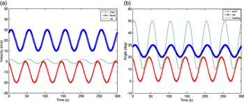
g. The SINS sampling rate is 100 Hz. The OD scale factor error is 0·2%. SINS pitch installation angle error is 5′ and heading installation angle error is 10′. The SINS location is north latitude 40°, east longitude 118° and height 400 m. The true velocity and attitude profiles for the first 300 s are shown in Figure 1.
The true velocity and attitude profiles for simulated scenarios: (a) velocity, (b) attitude.

4.2. The in-motion coarse alignment algorithm simulation
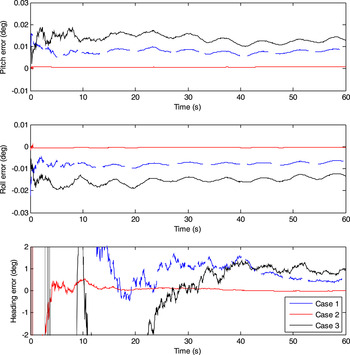
The coarse alignment lasts 60 s and runs 50 times. To further test the performance of the coarse alignment algorithm, three cases are considered, i.e., case 1, simulation uses perfect sensors (error-free gyroscopes, accelerometers, and no OD measurement errors); case 2, simulation with the omitted parts kept and case 3, simulation with sensor errors.
For all three cases, the average attitude errors of 50 times coarse alignment are illustrated in Figure 2. It can be seen that the two level misalignment angles, roll error and pitch error, converge immediately at the beginning and with a good precision (better than 0·02°) for all three cases. Specifically, the heading error takes longer than the two level misalignment angles to converge, and it stabilises at 0·5° in 50 s for case 1. This validates the correctness of the above analysis for the coarse alignment algorithm. In comparison with case 1, we can see that the heading accuracy increased in case 2. This is mainly because the omitted parts are included. We hope that the alignment algorithm is perfect with all parts being considered, but the omitted parts are unknown since these parts need the Earth's rotation angular rate in the b frame and the velocity in the n frame. As discussed previously, for the real sensors, the sensor errors would affect the accuracy in the same way as the omitted parts. Because of the sensor errors and omitted parts, the heading error in case 3 is larger than the heading error in case 1 and case 2, but it is still less than 1·5° after 60 s.
Average attitude errors of 50 times coarse alignment for three cases.

Consequently, the attitude errors calculated by the proposed in-motion coarse alignment algorithm can fulfil the requirement for the fine alignment. The convergent speed of the coarse alignment is fast, but owing to the sensor errors and omitted parts, it only accomplished the coarse estimation of attitude errors in the initial alignment. This is why the fine alignment is required. Next, the maximum of misalignment angles for case 3 are used as input for the fine alignment to validate the proposed in-motion fine alignment algorithm based on the KF in the fine alignment algorithm simulation.
4.3. The in-motion fine alignment algorithm simulation
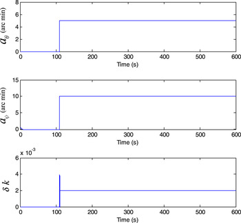
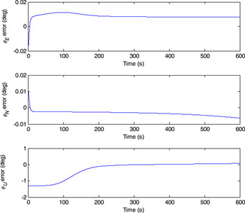
The simulation for fine alignment lasts 600 s and the step of the KF is set at 0.05 s. The estimation results of SINS installation angle error and OD scale factor error are presented in Figure 3 and the estimate errors of misalignment angles are plotted in Figure 4.
Estimation results of SINS installation angle error and OD scale factor error.

Estimate errors of misalignment angles.

It can be observed from Figures 3 and 4 that the proposed method can correctly estimate the SINS installation angle error and the OD scale factor error. The two level misalignment angles, roll error and pitch error, converge almost instantaneously with a high precision (better than 0·01°), and the heading error can achieve and accuracy of 0·05° in 300 s for the fine alignment stage.
5. EXPERIMENT RESULTS
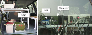
In this section, car-mounted experiments are performed to verify the validity of the proposed method. The setup of the experimental platform is shown in Figure 5, and composes a SINS system, an odometer and a GPS receiver. The SINS system consists of three ring laser gyroscopes with drift rate 0·005°/h (1σ ) and three quartz accelerometers with bias
 $5\times 10^{-5}$
m/s2 (1σ ) at output rate 200 Hz. The OD scale factor error is 0·1%. The GPS position accuracy is less than 3 m and the velocity accuracy is about 0·1 m/s, the GPS antenna's lever arm has been estimated and compensated.
Setup of the experimental platform.

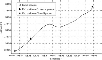
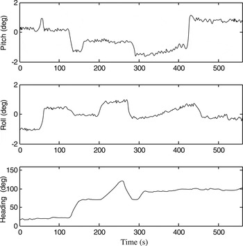
To evaluate the accuracy of alignment we needed a criterion for comparison. In this respect, the GPS-aided SINS had been already aligned before the experiment and was working in navigation mode, which is used to provide the reference attitude of high accuracy for the alignment performance comparison. The in-motion alignment experiment data was collected in Xi'an, China, and the test includes 60 s coarse alignment and 500 s fine alignment. The route of the experiment is shown in Figure 6 and the reference attitude derived by the GPS-aided SINS during the experiment is shown in Figure 7.
Route of experiment.

Reference attitude derived by the GPS aided SINS.

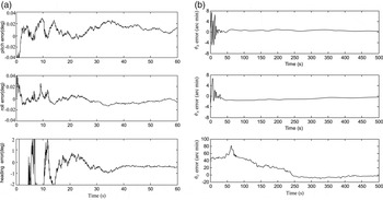
The attitude estimate errors of the alignment are presented in Figure 8. As can be observed in Figure 8(a), the convergent speed of the coarse alignment is fast, the two level misalignment angles reach 0.02° within 40 s, and the heading error reaches 1° within 40 s. The results of the coarse alignment method can fulfil the requirement for then achieving the fine alignment. It can be seen from Figure 8(b) that the heading error can reach an accuracy of 5 arcmin within 250 s in the fine alignment stage, and the two level misalignment angles can reach an accuracy of 1 arcmin within 50 s.
Attitude estimate errors of the alignment: (a) coarse alignment, (b) fine alignment.

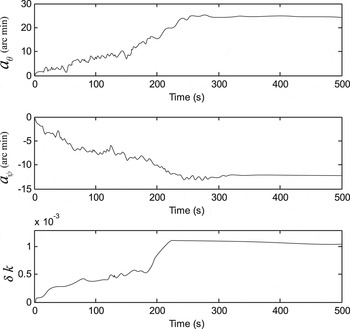
The estimation results of SINS installation angle error and the OD scale factor error are shown in Figure 9. We can see that the proposed method can correctly estimate the OD scale factor error, and the SINS installation angle error can be estimated after 300 s in the fine alignment stage.
Estimation results of SINS installation angle error and the OD scale factor error.

6. CONCLUSIONS
This paper proposed a complete in-motion alignment algorithm for vehicle-carried SINS based on OD aiding. Firstly, the in-motion coarse alignment method by using the integration form of the velocity update equation in the b frame to give a rough initial angle is introduced. Secondly, the in-motion fine alignment algorithm aided by the OD based on the KF is formulated, in which a new measurement equation in the b frame is established. This fine alignment algorithm can effectively improve the alignment accuracy and is also suitable for the in-motion alignment method aided by the motion constraints of the vehicle to provide a fault-tolerant alignment scheme for an OD fault. Simulation and experiment studies show that the results of the in-motion coarse alignment method can fulfil the requirement for then achieving the fine alignment, and the in-motion fine alignment algorithm can effectively improve the alignment accuracy.
ACKNOWLEDGMENTS
This work was supported by the National Natural Science Foundation of China (No. 41174162).