Introduction
Nanofluidics is the scientific investigation and technological application of fluid flow in and around nano-sized materials with at least one dimension below a few hundred nanometers. Reference Eijkel and Van Den Berg1,Reference Schoch, Han and Renaud2 It is interdisciplinary to many branches of science, including physics, chemistry, biology, materials, and geology, and it is an integral part of “nanotechnology.” Many devices, such as micro- or nanoelectromechanical systems (MEMS/NEMS), nanobiosensors, and lab-on-a-chip devices involve fluids at the nanoscale with potential applications such as water desalination, drug discovery and delivery, molecular sensing, energy production and storage, and many more.
Numerous challenges remain despite the enormous growth in this area over the past two decades. To make devices inexpensively and for their applications to become a commercial reality, we need to understand the science of their fundamental behavior and overcome experimental limitations in controlling and probing fluids confined to the nanoscale. For confinement widths less than a few nanometers, the well-established field of classical hydrodynamics based on the continuum hypothesis may fail.
Carbon nanotubes (CNTs) represent one of the smallest cylindrical nanopores (10,000× smaller than a single human hair) available today. Graphene is a two-dimensional ultrathin single layer of carbon atoms. These novel carbon-based materials have unusually high mechanical strength, excellent thermal and electric conducting properties, ultrasmooth hydrophobic surfaces, and high-aspect ratio. Water, of course, is the most ubiquitous molecule and one of the most vital elements of life. Even though it is the most studied substance on earth, we are still trying to understand its anomalous bulk properties, and we continue to discover new and fascinating properties of water in confinement.
In fluidics applications, both graphene and CNTs have shown super-lubricity, almost frictionless ultrafast mass transport, and high heat conduction. Amplifying the flow rates by reducing interfacial friction at the water–nanotube (or water–graphene) interface could have enormous economic advantages in applications, such as water desalination, by reducing energy usage. Water flow in CNTs has become the subject of intense research from the early 2000s. Reference Alexiadis and Kassinos3–Reference Kannam, Todd, Hansen and Daivis6 Various properties of water in CNTs—structural, thermodynamic, and transport—have been studied extensively using experimental, Reference Majumder, Chopra, Andrews and Hinds7–Reference Secchi, Marbach, Nigues, Stein, Siria and Bocquet16 computational, Reference Kannam, Todd, Hansen and Daivis6,Reference Du, Qu, Xia, Feng and Dai11,Reference Thomas and McGaughey17–Reference Wang, Dumont and Dickson24 and theoretical Reference Myers25,Reference Mattia and Calabro26 methods.
In this article, we focus on molecular dynamics (MD) studies of water flow in CNTs, which have specifically reported on slip length and flow enhancement. Experimental, continuum, multiscale, and MD studies with subnanometer diameter (single chain water) are discussed in articles by Calabrò, Corry, Kannam et al., Majumder et al., Min et al., and Borg and Reese in this issue.
Background
Hydrodynamics and Navier–Stokes equations
The continuum hypothesis that fluid properties, such as density, velocity, temperature, and pressure, are well defined at infinitesimally small points and vary continuously from one point to another, is at the heart of classical hydrodynamics. Reference Batchelor27 In most applications of fluid mechanics, the physical dimensions of the flow are extremely large compared to the molecular size and mean free path. Based on these assumptions, changes in flow properties are regarded as continuous, hence the continuum assumptions work well from the macroscale down to the microscale and even to the scale of a few nanometers. As a consequence, the Navier–Stokes differential equations based on the continuum hypothesis are used to solve hydrodynamic problems over a large range of length scales.
Hydrodynamic boundary condition
The hydrodynamic boundary condition (BC) is at the core of slip and flow enhancement of water in CNTs. It has been a subject of significant interest in recent times, even though the problem of formulating the BC has existed since the beginning of the 18th century. Reference Kannam28 The fluid transport coefficients along with the BC are used in the Navier–Stokes equations to solve for flow properties. The transport coefficients are intrinsic to the nature of the fluid, and there are several methods of measuring them accurately.
The BC is generally not derived from first principles, hence one often assumes the no-slip BC, according to which the normal component of the fluid velocity vanishes and the tangential velocity of the fluid relative to the adjacent solid is zero irrespective of the nature of both the fluid and solid. The no-slip BC leads to an exact analytical solution for some simple hydrodynamic problems. The general BC often used was first expressed by Navier using a quantity called slip length, l s , defined as:
 $${l_s} = {\eta \over \zeta }\,,$$
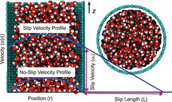
where ζ is the interfacial friction coefficient at the fluid–solid interface and η is the fluid shear viscosity. Reference Navier29 The slip length is defined as the length extrapolated into the wall at which the fluid velocity would be zero, assuming a linear extrapolation, as depicted in Figure 1 .
Schematic representation of water flow through carbon nanotubes (Poiseuille flow). The velocity profiles with and without slip, slip length (l S ), slip velocity (u S ), and velocity with respect to position (u r ) are depicted in the figure.

Hagen–Poiseuille flow
Hagen–Poiseuille flow refers to fluid flow between two parallel walls or in a cylindrical tube, such as water in CNTs under a pressure gradient. Consider the case where a fluid is confined in a cylindrical tube of radius, r t , and acted on by a uniform external field, F e (or a pressure gradient) along the z direction (see Figure 1). For this case, the Navier–Stokes equation reduces to the Stokes (or Poisson) equation, which in cylindrical coordinates (r, θ, z) is:
 $${1 \over r}{\partial \over {\partial r}}\left( {r{{\partial {u_z}\left( r \right)} \over {\partial r}}} \right) = - {{\rho {F^e}} \over \eta }\,,$$
where ρ is the fluid density and it is assumed that u z (r) (which represents flow in the z direction) must be finite at r = 0. Applying the no-slip BC (i.e., the fluid velocity at the wall r = r t is zero), yields the solution:
 $${u_z}\left( r \right) = \left( {{{\rho {F^e}} \over {4\eta }}} \right)\left( {r_t^2 - {r^2}} \right)\,.$$
The velocity profile across the tube is parabolic with maximum at the tube center r = 0 and zero at the tube surface r = r t . The mass flow rate through the tube can be obtained by integrating the velocity profile over the tube’s cross-sectional area.
Slip and flow enhancement
When the fluid has a nonzero velocity at the wall surface (slip velocity, see Figure 1), the velocity profile becomes:
 $${u_z}\left( r \right) = \left( {{{\rho {F^e}} \over {4\eta }}} \right)\left( {r_t^2 - {r^2}} \right) + {u_s}\,,$$
where u s is the slip velocity (i.e., the velocity of the fluid at the fluid–wall interface). Here, the fluid viscosity is assumed to remain the same in the presence of slip. The slip length and slip velocity are related via:
 $${u_s} = {u_z}\left( {{r_t}} \right) = {l_s}{\left( {{{\partial {u_z}} \over {\partial r}}\left( r \right)} \right)_{r\, = \,{r_t}}}\,.$$
The mass flow rate is enhanced in the presence of slip and the ratio of observed flow rate Q slip (in the presence of slip) to the expected flow rate Q no-slip (with no-slip BC) is termed flow enhancement and can be expressed as:
 $$E = {{{Q_{{\rm{slip}}}}} \over {{Q_{{\rm{no}} - {\rm{slip}}}}}} = \left( {1 + {{8{l_s}} \over d}} \right)\,,$$
for cylindrical geometry, where d is the diameter of the nanotube. For CNTs with diameter ≈ 0.8 to 10 nm, reported slip lengths of 1 to 500,000 nm for water resulted in flow enhancement factors of 0 to 500,000, respectively. The prospect of flow rates that are increased by up to five orders of magnitude has attracted significant attention from researchers in academia and industry to exploit this feature in applications such as water desalination and fluid transport at the nanoscale.
Earlier studies
Three studies in the early 2000s on water flow in CNTs generated significant interest in this area and debate on the concept of slip length. Hummer et al. Reference Hummer, Rasaiah and Noworyta30 used MD simulations and observed water flowing through tubes as narrow as 0.81 nm diameter as fast as in biological aquaporins (biological nanopores). Majumder et al. Reference Majumder, Chopra, Andrews and Hinds7 reported a slip length of 39,000 to 68,000 nm (flow enhancement 44,000 to 77,000) for a 7-nm-diameter tube, while Holt et al. Reference Holt, Park, Wang, Stadermann, Artyukhin, Grigoropoulos, Noy and Bakajin8 reported 140 to 1400-nm-slip length in 1.3 to 2.0-nm-diameter tubes. Experiments that have followed report widely scattered data—from as low as below 10 nm to 485,000 nm slip length for water in CNTs with diameter up to 10 nm. Nevertheless, a consensus has yet to be reached. Reference Secchi, Marbach, Nigues, Stein, Siria and Bocquet16
MD: Water in CNTs
Simulations of water in CNTs can be arranged in two ways. In the first, CNTs are connected to two water reservoirs, usually via graphene sheets attached to the ends of the nanotube. In the second, to avoid an increase in system size due to the reservoirs, nanotubes are filled with water (at a predetermined density) and connected via periodic boundary conditions (PBCs) in the axial direction.
NEMD: Slip length from velocity profiles
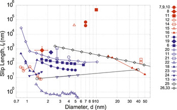
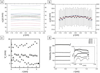
In nonequilibrium molecular dynamics (NEMD) simulations, an external force or a pressure gradient is applied to the water molecules along the axial direction. The streaming velocity profiles are analyzed to measure the slip velocity and slip length. The external forces used correspond to pressure differences three to four orders of magnitude higher than those used in typical experiments to achieve the required fluid velocities (generally above 10 m/s) and high signal-to-noise ratio within a few nanoseconds of simulated time. In Figure 2 , we compile the slip lengths reported in both experimental and simulation studies, which show a vast range of values extending almost six orders of magnitude. As can be seen from Figure 3 , Reference Falk, Sedlmeier, Joly, Netz and Bocquet20,Reference Kannam, Todd, Hansen and Daivis31,Reference Hanasaki and Nakatani32 where we display some of the flow velocity profiles taken from the literature, the fluid velocity gradient is small. This weakness in the velocity gradient makes the slip length extraction difficult and unreliable.
Slip length of water in carbon nanotubes. The results from experimental, simulation, and theoretical methods are shown in red, blue, and black, respectively. Reference numbers are given on the far right-hand side of the figure.

Poiseuille flow velocity profiles of water in (a–b) graphene nanochannels and (c–d) carbon nanotubes (CNTs). Some of the velocity profiles in (a) are inverted parabolas due to the small difference in the velocity from channel center to the walls. (b) The quadratic fits to the average velocity profiles (in [a]) constrained by the shear viscosity (blue) and unconstrained fits (red). The slip length extracted from the fits differ by more than 100% due to the small gradient in the velocity profiles. Reference Kannam, Todd, Hansen and Daivis31 (c–d) Non-quadratic nature of velocity profiles in CNTs. Reference Falk, Sedlmeier, Joly, Netz and Bocquet20,Reference Hanasaki and Nakatani32 For more non-quadratic water velocity profiles in CNTs, please see References Reference Thomas and McGaughey17, Reference Joseph and Aluru19, Reference Falk, Sedlmeier, Joly, Netz and Bocquet20, Reference Kotsalis, Walther and Koumoutsakos23, and Reference Wang, Dumont and Dickson24.

Thomas et al. Reference Thomas and McGaughey17 reassessed the results by Majumder et al. Reference Majumder, Chopra, Andrews and Hinds7 and Holt et al., Reference Holt, Park, Wang, Stadermann, Artyukhin, Grigoropoulos, Noy and Bakajin8 and hypothesized a miscalculation of the available flow area or the presence of an uncontrolled experimental variable (e.g., an electric field) in earlier experiments. For nanotubes of 1.66 to 4.99 nm diameter, they found slip lengths monotonically decreasing from 105 to 30 nm (433 to 47 enhancement). In a later study, they examined the fluid structure in narrow tubes of 0.83 to 1.66 nm diameter, and concluded that down to 1.39 nm diameter, the flow can be described by continuum theory by taking the slip into account. Reference Thomas and McGaughey18 Below this tube diameter, the fluid becomes highly structured with no clear trend in the flow rate. For the smallest diameter (0.83 nm), their results suggest a slip length of 1000 nm and a flow enhancement of 5000.
Joseph et al. Reference Joseph and Aluru19 conducted an investigation on the effects of nanotube smoothness and hydrophobicity, by varying the C–C bond distance (0.142 nm) and water–nanotube interaction strength. They concluded that a unique combination of features such as hexagonal structure, interatomic distances of 0.142 nm, and water orientations with “free” OH bonds pointing to the wall and decreased hydrogen bonding in the depletion region (only 5% bulk density near the wall surface) contribute to the large slip and flow rates of water in CNTs.
Babu et al. Reference Babu and Sathian22 measured the activation energy required by water molecules to overcome the potential barrier along the flow direction. They attributed the enhanced flow rates in smaller tubes to the decrease in activation energy and shear viscosity (calculated using the Eyring theory). They also found that the flow enhancement decreased from 65 to 2 as the tube diameter increased from 0.83 to 5.42 nm.
Ma et al. Reference Ma, Shen, Sheridan, Liu, Chen and Zheng21 found that for a 2.72-nm-diameter tube, slip lengths vary from 205 to 1120 nm with increasing contact angle, when the contact angle of water is varied from 45° to 135° through controlling the oxygen–carbon interaction strength. This indicated the importance of hydrophobicity on high slip. They proposed an inverse hyperbolic sine relationship between the water–CNT interfacial shear stress and slip velocity.
Myers Reference Myers25 proposed a theoretical model based on a depletion layer with reduced viscosity near the wall. This model predicted a slip length of 8.57 nm for a 1.4-nm-diameter tube; as the diameter increased to 40 nm, the slip length approached 35 nm. He argued that describing the slip length as the length scale over which the fluid layer slips over the boundary or, to be more specific, as “the distance the velocity profile at the wall must be extrapolated to reach zero” is misleading when the slip length is larger than the tube diameter. Mattia et al. Reference Mattia and Calabro26,Reference Ritos, Mattia, Calabro and Reese33 presented a model to predict the flow enhancement using the tube characteristic dimensions and fluid–wall interactions via the work of adhesion and surface diffusion. Their model suggests that the fluid velocity slip at the wall is solely a function of the fluid–wall interaction and is not a function of the tube characteristics or the pressure gradient, while the overall velocity profile depends on both.
In other studies, Du et al. Reference Du, Qu, Xia, Feng and Dai11 found a slip length of 260 nm for a 4-nm-diameter tube; Nicholls et al. Reference Nicholls, Borg, Lockerby and Reese13 found a slip length of 100 nm for a 0.96-nm-diameter tube; Kotsalis et al. Reference Kotsalis34 found an increasing slip length of 11 to 15 nm as the tube diameter increased from 2.71 to 5.42 nm; and Wang et al. Reference Wang, Dumont and Dickson24 found a slip length of only a few nanometers for tube diameters from 1.09 to 1.62 nm. Many other studies have focused on water flow and its transport properties in CNTs even though they have not explicitly reported the slip length or flow enhancement.
Equilibrium MD: Slip length from friction coefficient
Next, we briefly summarize two equilibrium MD methods Reference Bocquet and Barrat35,Reference Kannam, Todd, Hansen and Daivis36 that have been used to calculate slip lengths for the system of water in CNTs. Other methods have been proposed, but not necessarily used for water in CNTs described here, and thus will not be discussed. Reference Petravic and Harrowell37–Reference Bhadauria and Aluru41
Bocquet and Barrat Reference Bocquet and Barrat35 developed the first equilibrium MD-based method. They proposed a Green–Kubo type expression for the friction coefficient between the wall and the fluid. Falk et al. Reference Falk, Sedlmeier, Joly, Netz and Bocquet20 used their method and found a slip length that monotonically decreased from 2600 to 120 nm when the tube diameter increased from 0.81 to 7 nm, respectively. They showed a structural origin, the curvature-induced incommensurability between the water and CNT, to be a potential origin of high slip.
Hansen et al. proposed another method Reference Hansen, Todd and Daivis42 that explicitly takes into account only the local wall–fluid friction by separating out the viscous and frictional contributions. This method is not a Green–Kubo expression and does not rely on convergence of a time integral. Kannam et al. Reference Kannam, Todd, Hansen and Daivis6,Reference Kannam, Todd, Hansen and Daivis31 demonstrated that the model of Hansen et al. was able to accurately predict the slip length for systems of water confined to planar graphene and CNTs. Their comparisons were done against NEMD simulations of these systems under flow conditions and excellent agreement was found: a monotonically decreasing slip length from 180 to 75 nm when the tube diameter increased from 1.62 to 6.5 nm. They concluded that NEMD simulations must be analyzed carefully for high slip systems such as water flowing in CNTs, otherwise large errors may result from extrapolated slip lengths. The equilibrium method was found to be much more reliable.
Challenges and future directions
We next highlight and list some challenges in modeling fluid flow in nanopores and outline a few research directions that may resolve at least the order of slip and flow enhancement of water in CNTs by computational studies. Reference Kannam28
-
1. The relationship between the slip length and flow enhancement in Equation 6 assumes the fluid viscosity remains the same as in the bulk. NEMD studies of water in CNTs could not verify this assumption, as the difference in the fluid velocity from the center of the tube surface (and the curvature) is smaller than the statistical errors obtained in the streaming velocity profiles. With a pore-radius-dependent effective viscosity η(r t ), the enhancement becomes:
 $$E = {{{Q_{{\rm{slip}}}}} \over {{Q_{{\rm{no - slip}}}}}} = \left( {1 + {{4{l_s}} \over {{r_t}}}} \right){\eta \over {\eta \left( {{r_t}} \right)}}\,.$$
.
In the literature, results for the pore-radius-dependent effective viscosity are also scattered over two orders of magnitude. The discrepancy could be due to the breakdown of existing methods of defining and measuring viscosity for such highly confined fluids. Reference Todd and Hansen43,Reference Todd, Hansen and Daivis44 In the literature, non-quadratic velocity profiles were reported for channel widths of size five to six times the atomic diameter for simple atomic fluids. Reference Travis, Todd and Evans45 For water in CNTs, the slip length (and enhancement) has been reported for pores as small as 0.81 nm diameter, only approximately twice the size of water molecules. As previously mentioned, the quadratic nature of velocity profiles cannot be examined due to the extremely small strain rates of water in CNTs obtained from NEMD simulations. For such small molecular size pores, it is more useful to discuss the fluid transport using permeability and flow rate rather than viscosity and slip length. Both Equations 6 and 7 are valid only when the velocity profiles are quadratic.
-
2. NEMD methods have a few intrinsic limitations, for example, the systems can be simulated only for around 10 to 100 ns. This results in a few m/s standard error in the velocity profiles. In experiments, slip lengths on the order of 10 μm have been reported while the maximum slip lengths reported in NEMD studies are a few hundred nm, at least two orders of magnitude smaller. Recently, it was demonstrated that μm-range slip lengths cannot be measured from NEMD velocity profiles due to the extremely low-velocity gradients. Reference Kannam, Todd, Hansen and Daivis31
-
3. The external fields used in NEMD simulations are three to five orders of magnitude higher than the equivalent pressure gradients used in experiments. This is to achieve average velocities on the order of 10 to 100 m/s, which are comparable to thermal velocities (≈340 m/s for water at 300 K), and sufficient signal-to-noise ratio within a few nanoseconds simulation time. Extrapolating the slip length and flow rates from such high fields down to experimental conditions may not correspond to the linear regime where the flow rate increases linearly with the field and slip length remains constant. Reference Kannam, Todd, Hansen and Daivis46
-
4. The reasons for the three orders of magnitude difference in the maximum slip lengths reported in experiments compared to simulations need to be investigated further. It could be due to the empirical molecular models or some intrinsic limitations of MD simulations, or even errors in experimental measurements.
-
5. Most importantly, new theories taking into account confinement and nonlocal effects should be developed. Many other factors such as increased fluid–solid surface-to-volume ratio, the nature of the fluid–wall interface, the depletion region at the interface, and finite size effects of the molecules, all of which are safely neglected in classical hydrodynamics, should be considered. This is a complex but important problem to address in order to utilize the full potential of nanofluidics.
There are a number of other challenges to be considered—appropriateness of the chosen molecular potential energy functions; handling of electrostatic forces; Reference Wong-Ekkabut, Miettinen, Dias and Karttunen47 ambiguity of tube diameter definition for narrow tubes; entrance, exit and tube length effects; Reference Nicholls, Borg, Lockerby and Reese13,Reference Wang, Dumont and Dickson24,Reference Mattia and Calabro26,Reference Ritos, Mattia, Calabro and Reese33,Reference Su and Guo48 effects of water density inside the tube; Reference Alexiadis and Kassinos3 effect of directly thermostatting the confined fluid; Reference Bernardi, Todd and Searles49,Reference Sokhan, Nicholson and Quirke50 and flat curvature for high slip systems leading to essentially plug-like flow, making slip length extrapolation from NEMD data difficult. Reference Thomas and McGaughey17,Reference Kannam, Todd, Hansen and Daivis31
Conclusions
Fluid flow in nanopores, particularly water flow in CNTs, has many potential applications. For tubes with a subnanometer to 10-nm diameter, slip length and flow enhancement data are scattered over one to five orders of magnitude. A combination of features such as the smooth surface of CNTs, hydrophobicity (weak interaction between water and CNTs), orientation of OH bonds near the tube surface, low activation energy, smooth potential energy landscape, depletion region with low density, and reduced viscosity are found to be the reasons for high slip and flow rates of water in CNTs.
For high slip systems such as water in CNTs, flow enhancement measurements using the slip length need to be performed carefully as it is a highly sensitive quantity. Research addressing some of the challenges highlighted and future directions indicated in this article may be able to resolve some of the discrepancies in modeling the slip and flow enhancement of water in CNTs and further increase our understanding of the transport properties of fluids and nanofluidics in general.

Sridhar Kumar Kannam is a postdoctoral researcher at IBM Research–Australia. He received his master’s degree from the University of Hyderabad, India, and his PhD degree in nanofluidics from Swinburne University of Technology, Australia. His research interests include the application of molecular modeling and computer simulation techniques to problems related to nanotechnology, nanofluidics, liquid–solid interfaces, and materials. Kannam can be reached by phone at (+61) 04 3060 0771 or by email at urssrisri@gmail.com.

Peter J. Daivis has been a professor of physics at the Royal Melbourne Institute of Technology (RMIT) University, Australia, since 2011. He completed his undergraduate and master’s degrees in applied physics at RMIT University, and a graduate diploma in applied colloid science at Swinburne Institute of Technology, Australia. After completing his PhD degree in physics at Massey University, New Zealand, he was appointed to a postdoctoral position at The Australian National University. His research focuses on experimental, computational, and theoretical studies of soft matter, and includes nonequilibrium statistical and thermal physics, computational nanofluidics, and generalized hydrodynamics. Daivis can be reached by email at peter.daivis@rmit.edu.au.

Billy Todd is a professor and chair of the Department of Mathematics at Swinburne University of Technology, Australia. He completed his undergraduate and postgraduate studies in physics at The University of Western Australia and Murdoch University, Australia. He then completed postdoctoral appointments at the University of Cambridge, UK, and The Australian National University, before moving to the Commonwealth Scientific and Industrial Research (CSIR) Organisation in Melbourne, Australia, in 1996. His research interests include statistical mechanics, nonequilibrium molecular dynamics, and computational nanofluidics. He is a Fellow of the Australian Institute of Physics and a former President of the Australian Society of Rheology. Todd can be reached by phone at +61 3 9214 8740 or by email at btodd@swin.edu.au.