Introduction
The 5 G millimeter-wave (mmWave) technology has captured significant interest due to its large bandwidth and high data rate [Reference Hong, Baek and Ko1–Reference Andrews, Buzzi, Choi, Hanly, Lozano, Soong and Zhang3]. Regarding the inherent transmission loss in air is negligible under mmWave band, phased arrays become one of the key technologies, and have attracted the extensive attention. Phased arrays have more flexible beam pointing and strong anti-interference performance; therefore, phased arrays are widely employed to attain dynamic point-to-point high data rate wireless communication [Reference Qu, Qu, Zhang, Yang and Chan4–Reference Gao, Wang, Fan, Zhang, Wang, Wu, Liu and Pedersen6]. In this circumstance, the phased arrays with the ability of wide-angle scanning, wideband, high-gain characteristics, as well as compact sizes are highly required.
There are many types of antennas that can achieve wide-angle scanning performance, such as electromagnetic dipoles, substrate integrated waveguide (SIW) horn antennas, patch antennas, SIW/ridged substrate integrated waveguide (RSIW) slot antennas, planar inverted-F antenna antennas, etc. However, since the mutual coupling between the array elements becomes stronger with the scanning angle increases, the wide-angle scanning performance is still limited by mutual coupling nowadays [Reference Kavitha and Raglend7]. Among different type of antennas, RSIW slot antennas combine the advantages of ridge waveguides and SIW together [Reference Bozzi, Pasian, Moscato, Moro and Perregrini8, Reference Kazemi and Fathy9]. RSIW slot antennas have lower cutoff frequency of the dominant mode and wider single-mode operating bandwidth [Reference Kazemi and Fathy10]. In terms of fabrication feasibility and cost, RSIW slot antennas have lower cost compared to ridge waveguides and are easier to integrate with planar circuits. Compared to SIW slot antennas, RSIW slot antennas have advantages of wider bandwidth, lower sidelobe, and smaller size [Reference Ding and Wu11]. Furthermore, adjustable ridge dimensions can minimize the waveguide width, which theoretically can make the scanning angle reach ±90° without generating grating lobes [Reference Wang, Zhong, Zhong and Liang12, Reference Zhong, Wang and Liang13]. However, though the advantage of RSIW slot antenna is obvious, it still has some technical challenge to solve. The RSIW slot antenna is resonant antenna, which typically have narrow bandwidth. Furthermore, due to the internal dielectric materials inside and low profiles, the mutual coupling between array elements is extensive, which has adverse influence on the impedance bandwidth and gain.
Many methods have been used to improve the impedance bandwidth and gain of phased arrays. Common approaches to solving bandwidth issues include adding new resonance points, designing wideband feeding networks, and dividing the antenna into multiple subarrays. Methods to improve antenna gain include increasing the physical area of the radiation aperture, enhancing directionality to achieve uniform E-field distribution on the aperture surface, and reducing losses to improve radiation efficiency. For instance, in paper [Reference Liu and Yan14], a dual-polarized SIW cavity-backed coupling fed slot element antenna was proposed. It employed to design a 1 × 4 phased array that covers the frequency range of 25.8–28.8 GHz (11%), and has a scanning range greater than ±41°. In paper [Reference Sun, Li and Zhang15], an open-ended cavity structure was employed, giving rise to a compact 4 × 4 end-fire phased array, attaining a wide bandwidth of 24.5–29.5 GHz (18.5%) and a scanning range greater than ± 46°. In paper [Reference Zhang, Zhao, Wang, Zhang and Pedersen16], an end-fire phased array for 5 G (27.5–29.5 GHz, 7%) handset devices was proposed, and scanning range of ±44° was achieved by introducing two transition plates to improve the impedance matching. In paper [Reference Moreno, Ala-Laurinaho, Khripkov, Ilvonen and Viikari17], the proposed phased array showed a realized gain above 6 dBi within the frequency of 28–33 GHz (13%) and achieve beam-steering up to ±40°. In paper [Reference Stutzman and Thiele18], a low-cost and low-profile magnetic actuator is introduced to precisely control the phase shifter, and the phased array achieves the bandwidth of 29.5–30.5 (3.3%) and scanning range of ±38°.
However, as mentioned above, most reported mmWave phased-arrays have limited bandwidth, scanning range and the gain. To meet the requirements of mmWave 5 G (24.25–29.5 GHz) standards, a novel wideband and high-gain phased array antenna based on low-temperature co-fired ceramic (LTCC) technology is proposed in this paper for wide-angle scanning. The verification results show that the phased array can obtain a good beam-scanning capability covering a large bandwidth of ∼20%, the scanning angles extend up to ±55° covering the entire bandwidth of 24.25–29.5 GHz. The isolation of ports remain below −15 dB and the gain over 14.5 dBi with minimal variations.
Design of RSIW slot antenna subarray
The type of antenna subarray is a slot antenna based on RSIW. The proposed subarray consists of two parts: the radiator and the feeder. The radiator comprises several staggered longitudinal slots on the RSIW. The feeder comprises a T-junction power divider feeding RSIW through slot coupling, and the feeder transit from ground coplanar waveguide (GCPW) to (SIW. LTCC technology is employed in this design, since it can offer arbitrary inter-layer via, offering higher design flexibility compared to standard Printed Circuit Board (PCB)/ High-Density Interconnect (HDI) process.
Design of element RSIW slot antenna
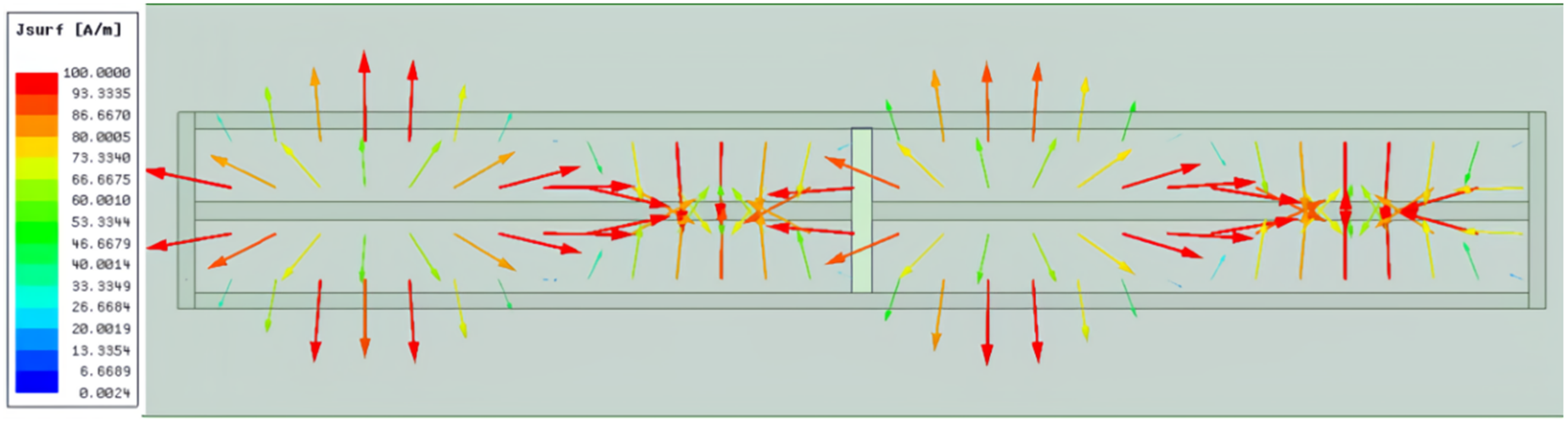
The relative height between the ridge and waveguide significantly impacts overall performance of the RSIW slot antenna. As observed from the simulation. For the ridge height h 2, when the ridge height increases, it will reduce the cutoff frequency of some modes, thereby increasing the difference in cutoff frequencies between different modes, and thus expanding the single-mode transmission bandwidth. By adjusting the ridge height h 2, the operating frequency range of the antenna can be extended. Therefore, the ridge height should be optimized well to achieve the broader bandwidth and higher gain. The working principle of RSIW is similar to SIW, which can be observed from the surface current distribution in Figure 1. The staggered longitudinal slots along the center line of the wide side are cut by the current distribution lines, then the displacement currents can be generated on both sides of the slots, where electromagnetic waves can be excited. This current distribution specifies the level of power coupled from the waveguide to the slot and consequently radiation from the slot. The cutting directions of each slot should be consistent, to ensure the electric field are in the same polarization, which can maximize the aperture efficiency. In initial simulation, the complex metallized via model is transformed into an equivalent metal wall to save the simulation cost.
Surface current distribution of RSIW slot.

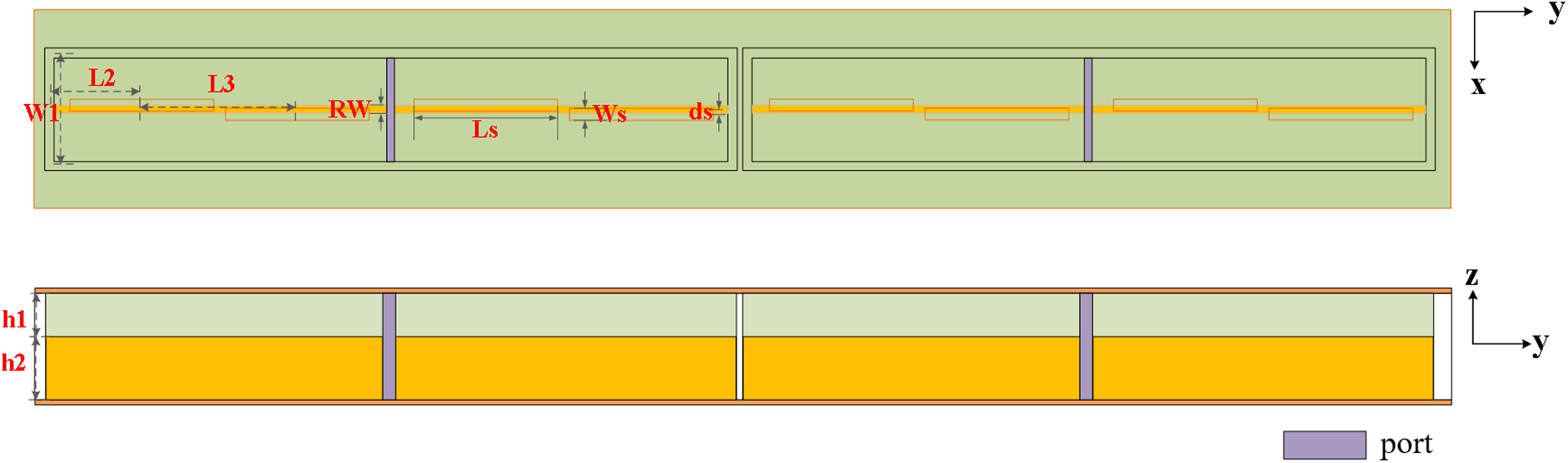
The radiators are implemented on an eight-layer LTCC dielectric substrate, since it has higher dielectric constant, which can make the size more compact. The LTCC process utilized in this design is FerroA6M (ε r = 5.9, tanδ = 0.002), and the single-layer substrate thickness is 0.094 mm. To achieve higher gain, eight slots are set as radiation elements, which are further divided into two subarrays to form the radiator. The topmost metal layer is etched with eight staggered longitudinal placed radiation slots along the center line of the wide side, each with a length of L s and a width of W s. The length from the slot to the short-circuit end is L 2, the offset from the center line is d s, and the spacing between adjacent slots is L 3. The top and side views of the antenna subarray are shown in Figure 2.
Top and side views of the RSIW slot antenna subarray.

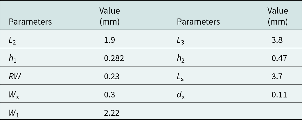
It was found that due to the strong electric field above the ridge, the offset of the slot from the center line (ds) has a significant impact on radiation performance. As observed from the simulation, when the slot deviates from the center line, the electric field distribution around the slot is disrupted, and can cause the main beam direction to shift. When the slot is offset toward one side, the radiation pattern may be tilted towards the opposite side. When the slots are too far from the center line, it may cause the antenna to become more capacitive or inductive, leading to impedance mismatches, result in increased return loss and voltage standing wave ratio (VSWR). The length from the slot to the short-circuit end (L 2) and the spacing between adjacent slots (L 3) mainly affect impedance matching. Additionally, the ridge width (RW) and ridge height also have impact on matching. The higher height can easily result in higher-order mode, while the lower height can cause waveguide cutoff. After optimization, the specific dimension values are presented in Table 1.
Dimension parameters of the RSIW slot radiation element

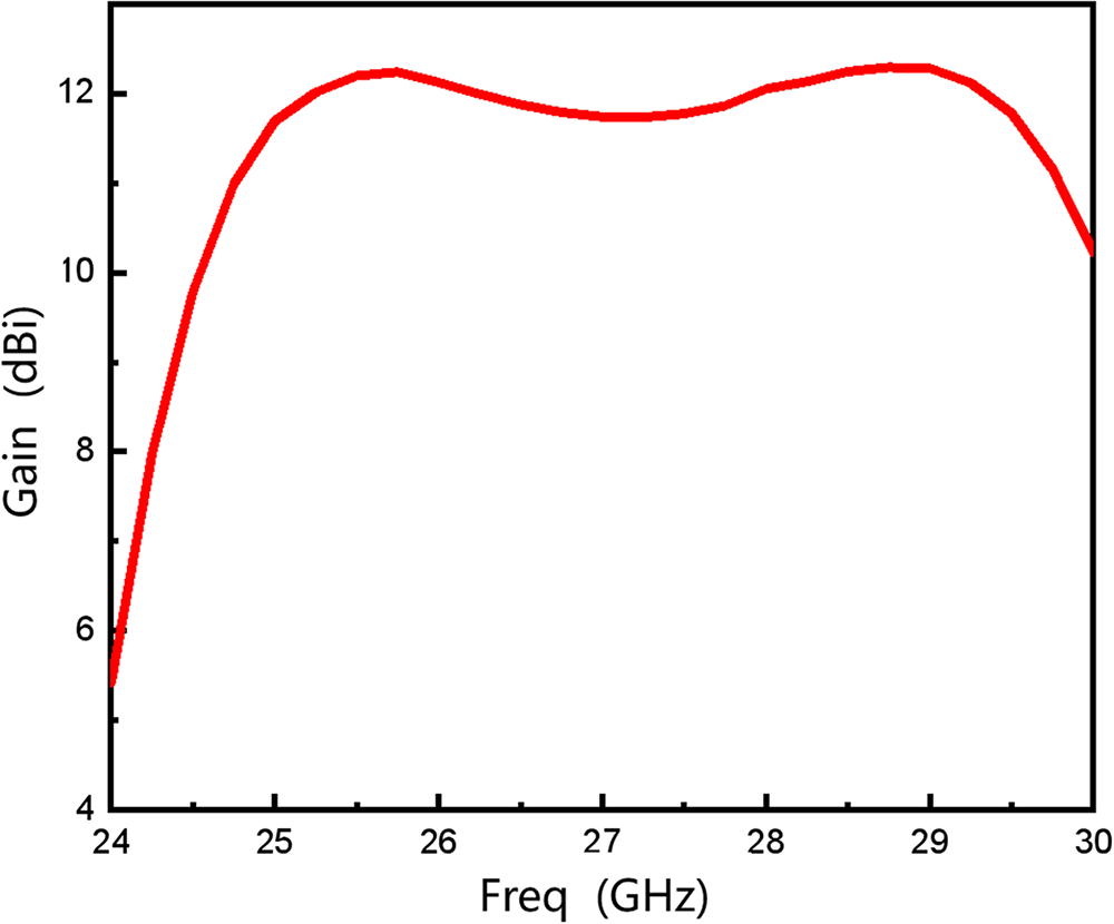
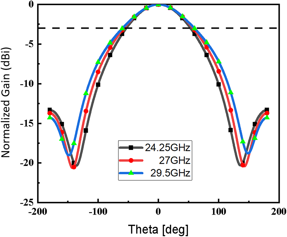
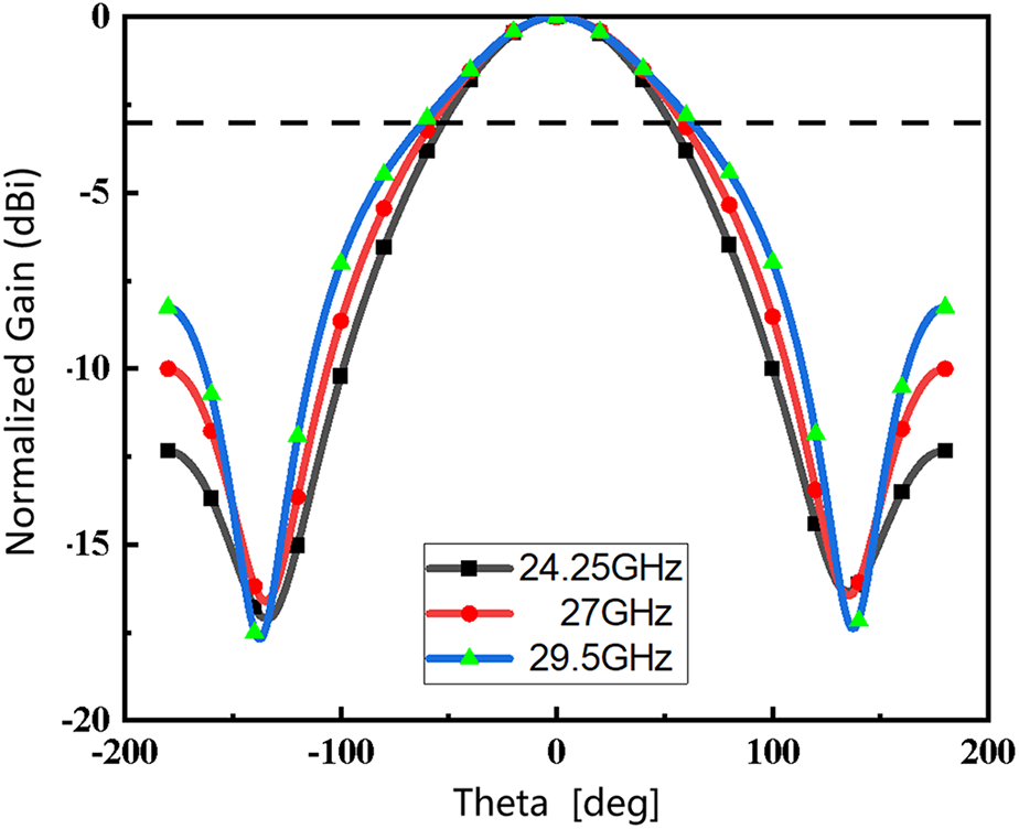
The ports of the two subarrays are excited by equal amplitude and anti-phase excitation. The gain within the operating band is shown in Figure 3. It can be seen that the gain is above 11 dBi at most frequencies with minimal variation. Figure 4 shows the normalized radiation patterns at different frequencies. The half-power beamwidth of the radiator is above 106° within the operating band. The minimum beamwidth is 106° at the low-frequency point of 24.25 GHz, and the maximum beamwidth is 125° at the high-frequency point of 29.5 GHz. The radiation performance demonstrated by this radiator is desirable, meeting the scanning requirements of 5 G-mmWave phased array.
Simulated gain of the RSIW slot antenna subarray.

Normalized radiation patterns of the RSIW slot antenna subarray at 24.25, 27, and 29.5 GHz.

Design of series-parallel feeding network
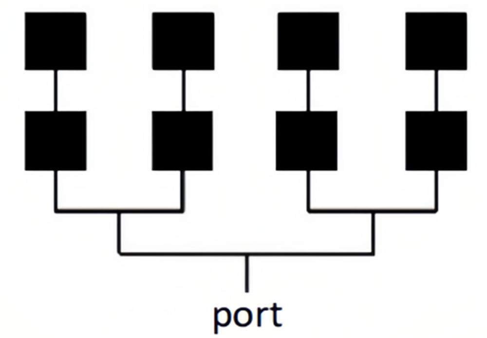
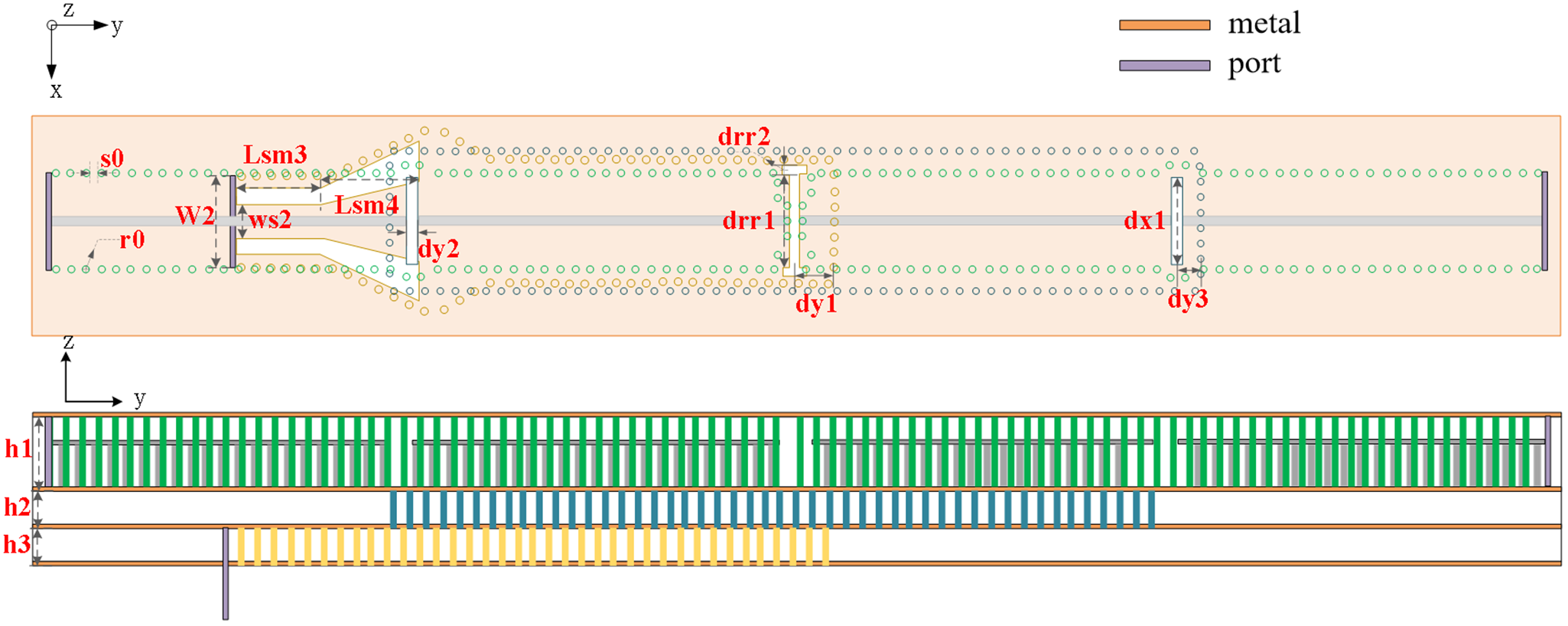
The feeding network adopts series-parallel combined feeding approach; the diagram is illustrated in Figure 5. This approach ensures consistent path lengths from the excitation source to each radiator section, where a single coupling path sequentially feeds multiple radiator elements. This approach combines the advantages of both series and parallel feeding, achieving both broadband and low-loss characteristics. As depicted in Figure 6, the upper layer of RSIW can utilize an aperture-coupled feeding method. The H-plane T-junction power divider consisting of two layers of SIW is employed in this design. A one-to-two power divider network is placed on the lower layer, while the upper layer sequentially feeds two radiation slots through a single coupling path, then eight slots can be equally fed. Additionally, due to the higher cutoff frequency of SIW than that of RSIW, which can cause the different element spacing after array formation. To avoid this, the width of the lower SIW layer is kept similar to that of the upper RSIW by selecting an I-shaped slot for energy coupling.
Schematic diagram of series-parallel feeding network.

Schematic diagram of SIW-fed RSIW.

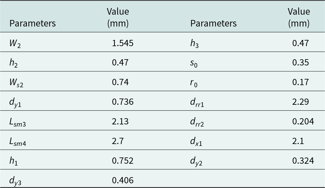
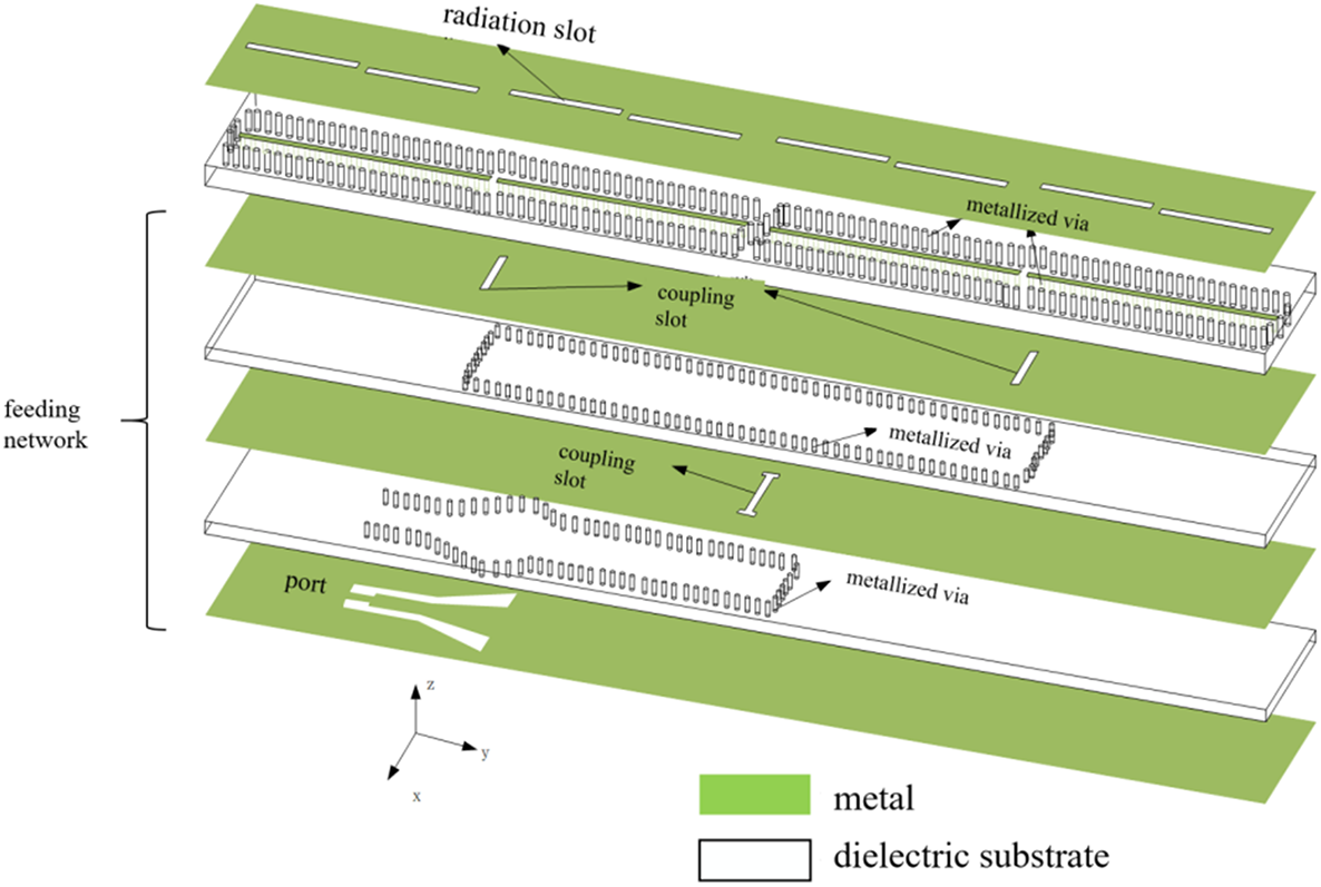
The antenna is connected to a 50-Ω coaxial line via SMPM connectors. Energy is fed through the lowermost port, transformed from quasi-TEM mode to TE10 mode in the waveguide via a GCPW-SIW transition. The lowermost five layers of dielectric substrate are set with a thickness of h 3. The lowermost metal layer serves as a ground for the middle SIW layer, on which an I-shaped slot is etched for energy coupling. The middle five layers of dielectric substrate is set with thickness of h 2, and the middle metal layer serves as the ground for the upper RSIW. Two straight slots are etched on the middle metal layer, to couple energy to the upper RSIW radiation slots. Table 2 provides the optimal dimension values for the GCPW-SIW-fed RSIW structure.
Dimension parameters of the feeding network

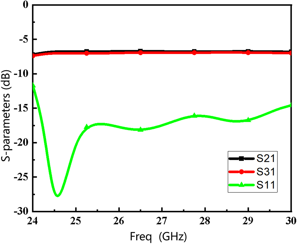
The simulated results of this two-layer (in bottom and middle layer) series-parallel SIW feeding network are presented in Figure 7, showcasing its S-parameters and transmission loss, showcasing its S-parameters and transmission loss. Evidently, this series-parallel combined feeding network exhibits wideband characteristics, with a −15 dB impedance bandwidth covering 24.25–29.5 GHz, fulfilling the design requirements for 5 G mmWave bands. Transmission loss within the operating band ranges from 6.63 to 7.03 dB/port, with a variation less than 0.5 dB. The simulated results indicate that GCPW-SIW-fed RSIW has good transmission properties and low loss.
The simulated S-parameters of series-parallel SIW feeding network.

Assembly of antenna subarray
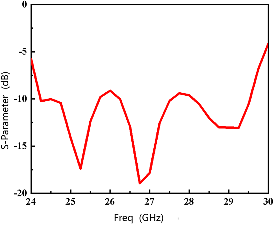
The optimized radiation section is connected to the feeding network, and the three-dimensional schematic of the overall structure is shown in Figure 8. The performance is simulated and optimized using ANSYS HFSS. As can be seen from Figure 9, the antenna subarrays cover an operating bandwidth of 24.25–29.5 GHz, with an absolute bandwidth of 5.25 GHz and a relative bandwidth of ∼20% for VSWR less than 2.
Exploded view of antenna subarray.

Simulated S11 of antenna subarray.

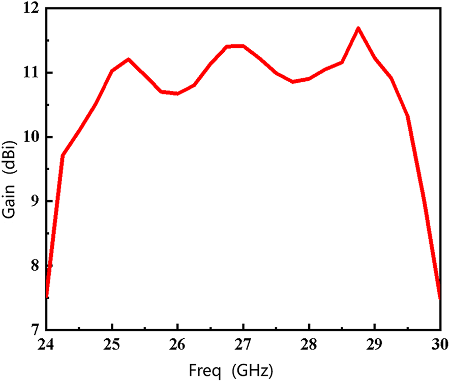
Figure 10 shows the gain variation in the 0° direction within the operating bandwidth of the antenna subarray. It can be seen that the gain variation within the operating bandwidth is stable, with a minimum of 10 dBi and a maximum of 11.5 dBi of gain. Figure 11 presents the E-plane radiation patterns at 24.25, 27, and 29.5 GHz. It can be observed that the overall radiation performance of the antenna subarray with the feeding network remains stable, with a beamwidth above 106° for each element. The minimum beamwidth is 106° at the low-frequency point of 24.25 GHz, and the maximum beamwidth is 124° at the high-frequency point of 29.5 GHz.
Simulated gain of antenna subarray.

Normalized radiation patterns of the antenna subarray at 24, 25, 27, and 29.5 GHz.

Assembly of phased array antenna
The designed subarrays are equally spaced in line to form a four-element array, and the array structure is shown in Figure 12. As observed from the simulation, when the element spacing exceeds a certain threshold, grating lobes may appear, and element spacing affects the level of side lobes continuously. Larger element spacing can lead to higher side lobe levels, which can cause unwanted radiation in non-main beam directions, reducing the efficiency of the main beam. To avoid grating lobes during scanning, the element spacing should be less than 0.53λ 0, which is finally optimized as 0.412λ 0. The overall dimension of the array antenna is 1.68 × 3.136 × 0.15λ 0 @ 26.875 GHz.
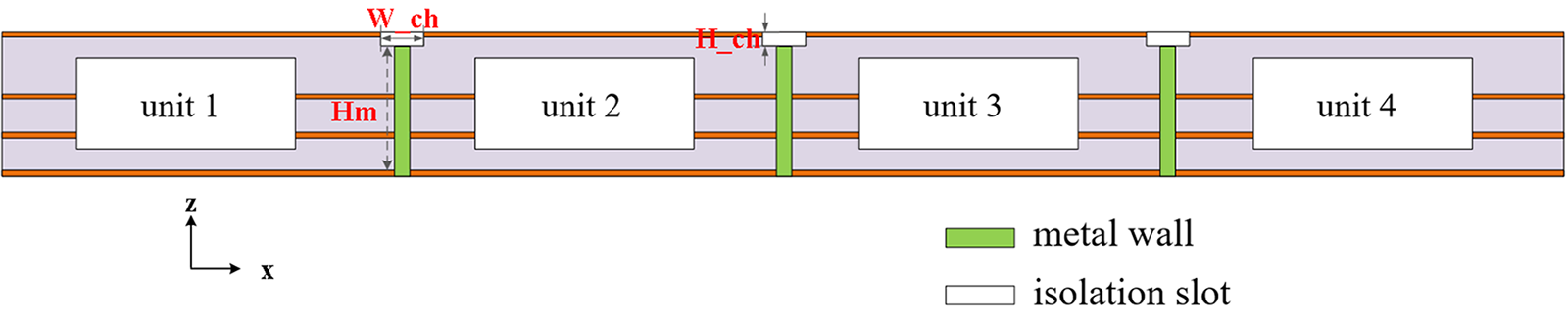
Side view of the antenna array.

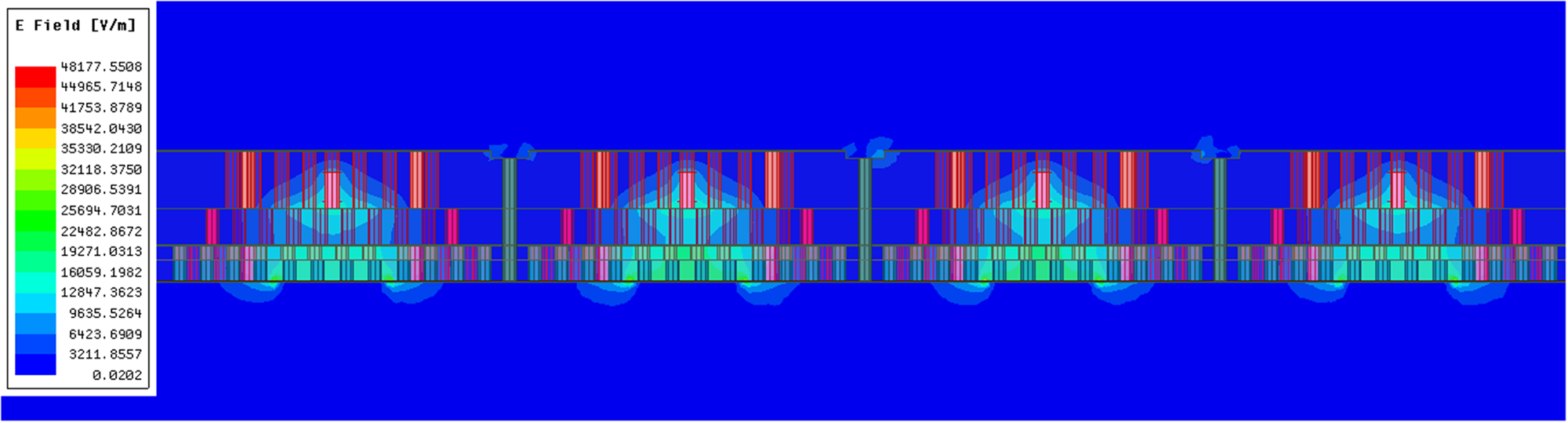
The phased array radiation pattern is influenced by both the element factor and the array factor. Scanning performance can be improved by enhancing inter-element isolation. Removing a piece of metal between elements on the ground plane of the RSIW, to block electromagnetic waves from propagating in the form of surface waves can reduce inter-element coupling and improve isolation. Furthermore, the physical barriers such as metal walls and isolation slots can easily be added between elements to block electromagnetic wave propagation through the substrate, thereby reducing coupling. The dimensions of the designed antenna are given as follow. The width of the isolation slot W_ch is 0.5 mm, and the depth of the excavated dielectric substrate H_ch is 0.094 mm. The height of the metal wall under the isolation slot H m is 1.598 mm. The electric field distribution on the scanning plane of the array antenna is shown in Figure 13. As can be seen, most of the fields reside between the ridge and the upper wall of the waveguides, and it is possible to observe greater concentration of electric field in region above the ridge. The electric field distribution within the cross section of the RSIW shows that the adoption of ridge can control the electric field distribution. Since the feeding network is SIW, the surrounding metal posts can well confine the energy, resulting in minimal mutual coupling between array elements after assembly. Except for a small amount of energy coupled in the form of surface waves, there is little energy coupling in the middle layers. Furthermore, block effect of isolation slots by removing a piece of metal can also be observed, reducing the coupling and improve isolation between the array elements.
Electric field distribution on the scanning plane XOZ at 27 GHz.

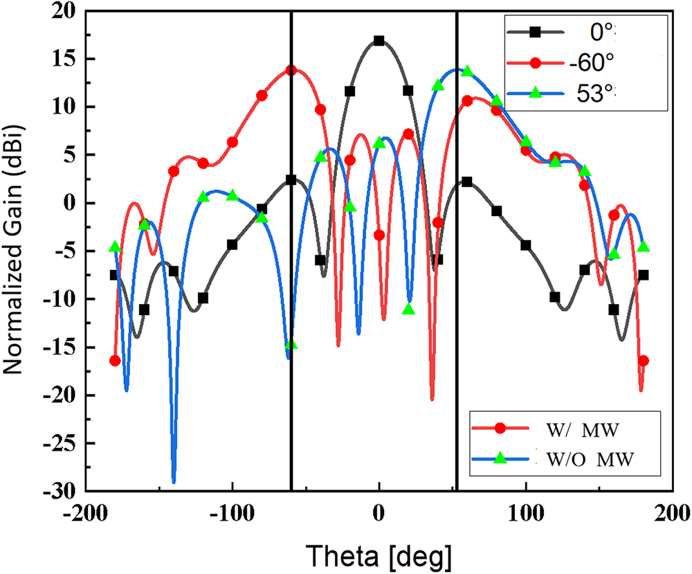
As observed from optimization, after the assembly, the main factors affecting the scanning angle of the phased array lie in the depth of the isolation slot and the metallized via hole added under the isolation slot. Figure 14 shows the scanning patterns with and without metal vias under the isolation slot at 27 GHz. The maximum scanning angle with metal vias is ±60°, while the maximum scanning angle without a metal vias is only ±53°, with a difference of ±7° corresponding to a 3 dBi gain drop. It indicates that adding a metal vias improves isolation and array scanning performance, while the requirement of difference between the main lobe and the side lobes should be less than 3 dB is still satisfied.
Impact of the metal vias on the scanning performance of the antenna array.

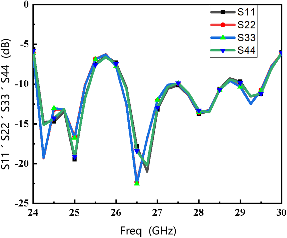
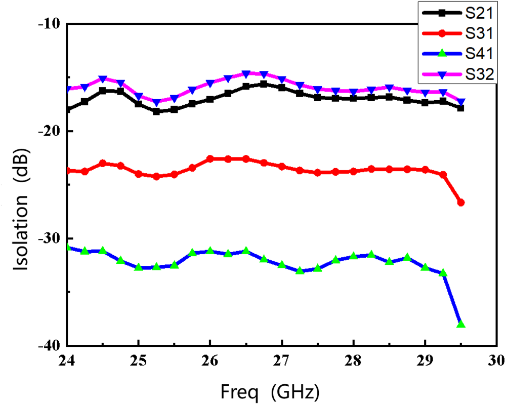
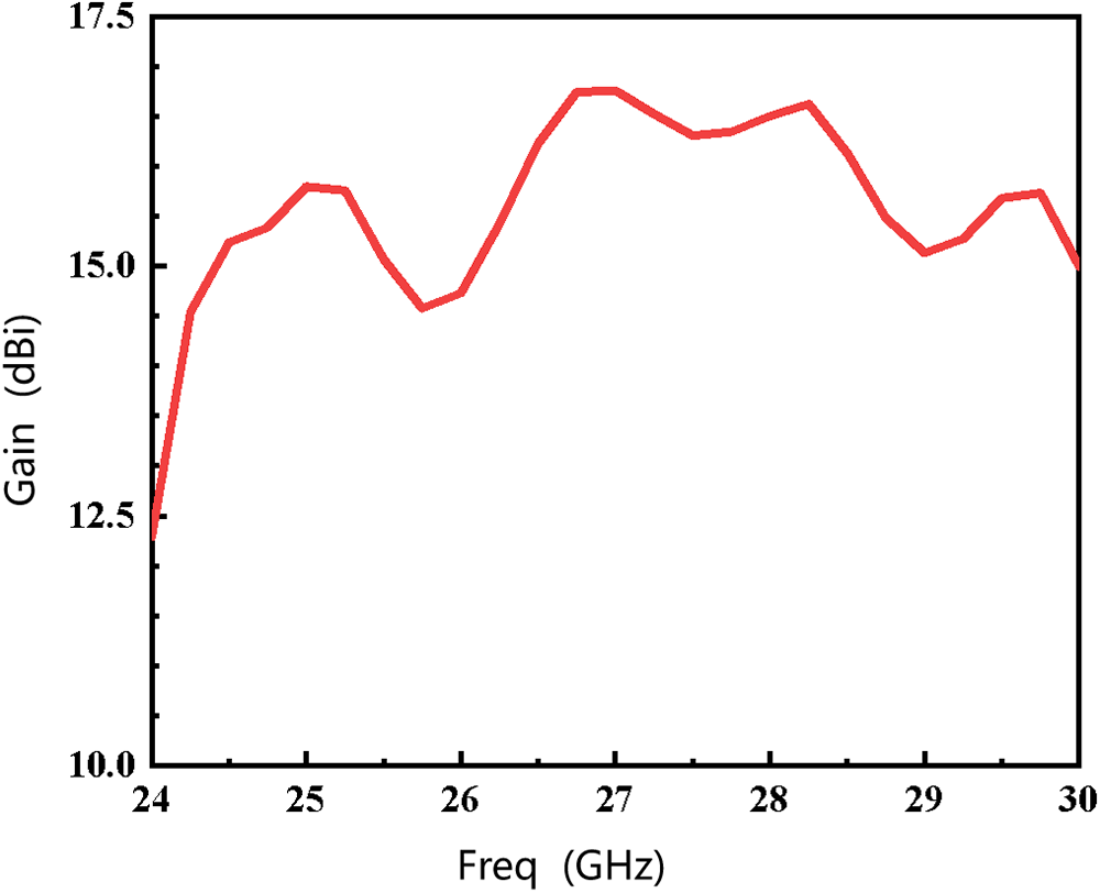
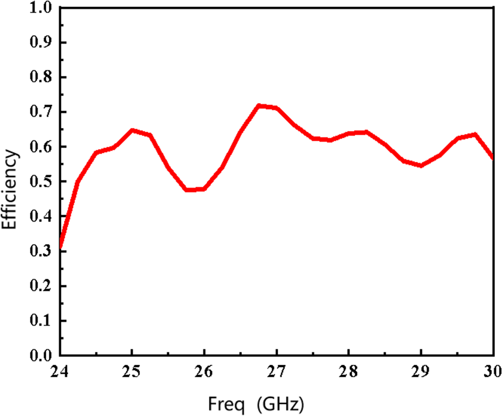
Each port of the 1 × 4 array is excited with equal amplitude and in-phase excitation. As shown in Figure 15, the S11 covers most frequencies of 24.25–29.5 GHz. Figure 16 shows the isolation between adjacent ports of the antenna. The isolation of ports 12, 23, 31, and 41 can reach below −15 dB, exhibiting good coupling performance. Figure 17 shows the actual gain within the operating bandwidth is above ∼15 dBi, with the gains corresponding to the upper and lower limits of the operating frequency being 14.5 dBi @25.8 GHz and 16.8 dBi @ 27 GHz. Since the antenna adopts the series-parallel combined feeding network, that the stability of the radiation pattern is better than that of only series feeding. Figure 18 shows the efficiency of the antenna, which is above 50% within the frequency band.
Simulated reflection coefficient of the antenna array.

Simulated isolation between elements of the antenna array.

Simulated gain of the antenna array.

Simulated efficiency of the antenna array.

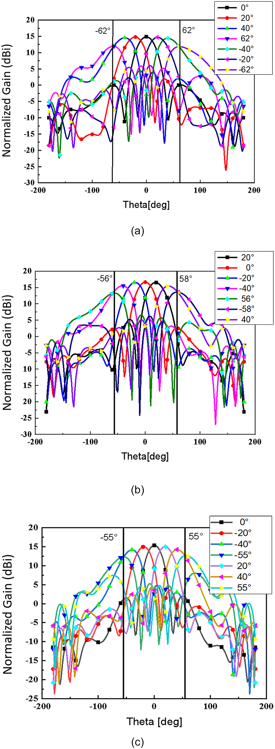
Figure 19 presents the gain pattern on the scanning plane at 24.25, 27, and 29.5 GHz. It can be observed that the array antenna can achieve a minimum scanning range of ±55° and a maximum scanning range of ±62° within the operating bandwidth in the E-plane (Phi = 0 plane). As the phase increases, the scanning angle increases, and the gain drop is relatively smooth. At the lowest frequency of 24.25 GHz, the gain in the 0° direction is 14.7 dBi, there is no significant gain drop when scanning to ±20° and ±40°, the scanning angle corresponding to 3 dBi gain drop is ±62°. At the mid-frequency of 27 GHz, there is a slight gain drop when scanning to ±20° and ±40°, and the scanning angle corresponding to 3 dBi gain drop is ±58°. At the highest frequency of 29.5 GHz, there is still a slight gain drop when scanning to ±20° and ±40°, and the scanning angle corresponding to 3 dBi gain drop is ±55°. It can be seen that as the frequency increases, the antenna beam scanning always meets the specification requirement of a ±55° scanning angle for the four-element array within the operating bandwidth.
Scanning pattern of the antenna array in the XOZ plane at (a) 24.25 GHz, (b) 27 GHz, and (c) 29.5 GHz.

Measurement and results
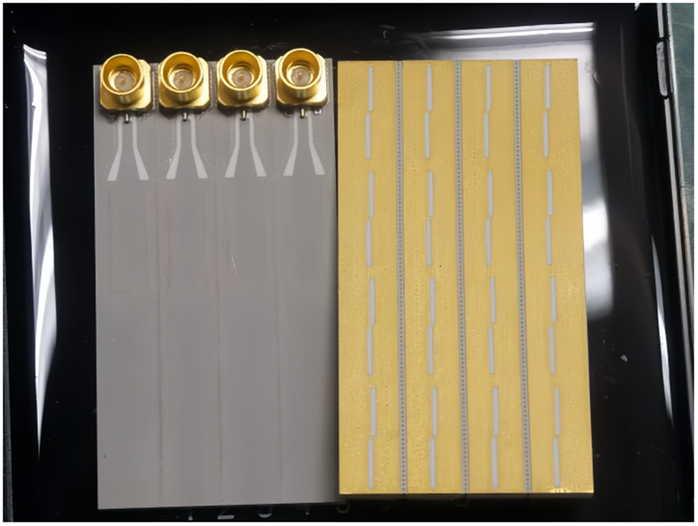
The antenna array is fabricated and measured according to the proposed design to verify the performance. The fabrication is carried out using the LTCC process, with FerroA6M material for the substrate. The overall thickness of the antenna is 1.692 mm, consisting of 18 layers of 0.094 mm dielectric substrate. The fabricated prototype is shown in Figure 20. To prevent oxidation of the antenna metal, a layer of gold was plated on the metal surface of the antenna.
Prototype photograph of the fabricated phased array antenna.

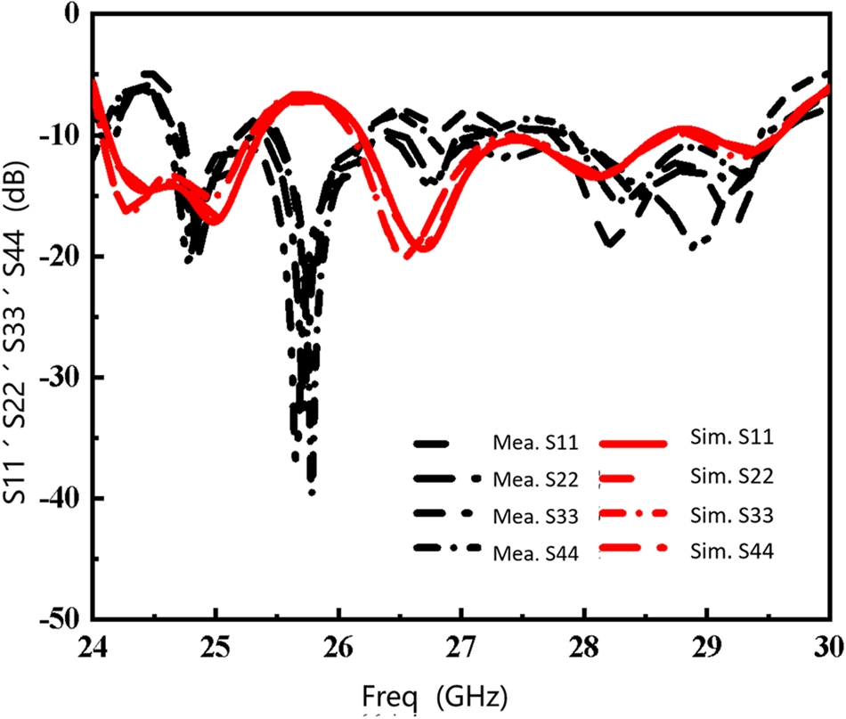
The antenna array is connected to 2.92-mm SMPM connectors with a characteristic impedance of 50 Ω. The matching and radiation performance of the antenna were tested using a Vector Network Analyzer (R&S ZVA67 VNA) and a microwave anechoic chamber (MVG Satimo StarLab). Figure 21 presents the simulated and measured reflection coefficient for the four ports of the array antenna. It can be observed that the measured S11, S22, S33, and S44 exhibit a consistent trend with their simulated results, with minor frequency deviations. These deviations are attributed to the influence of the actual test environment and the shrinkage of the LTCC substrate after processing, resulting in operating frequencies higher than simulated frequencies. The resonance point at low frequency is slightly lower than the simulated results, which may be due to welding errors between the antenna and SMPM connector. These errors are within the normal range of variation.
Simulated and measured results of S-parameters for each port of the antenna array.

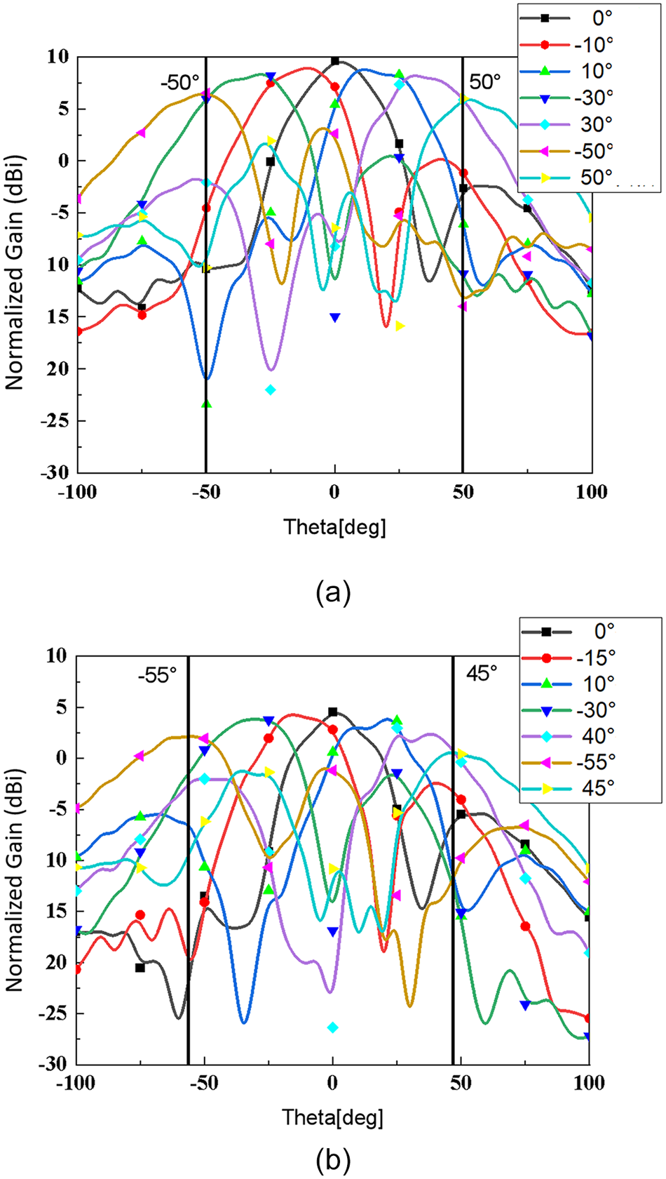
Figure 22 (a) and (b) shows the continuous scanning patterns of the antenna’s XOZ plane (E-plane) at frequency points of 27 and 29.5 GHz, respectively. The results reveal that the overall measured scanning angle is ±5° lower than the simulated results. At high frequencies, a shift is observed, and minor differences exist in both the pattern and gain values. These differences are partly due to processing and assembly errors and partly due to errors introduced by the test environment, but they are all within acceptable limits. Based on the above measurement, the performance of the antenna’s simulation results is effectively validated.
Measured scanning patterns of the antenna array XOZ-plane scan at (a) 27 GHz and (b) 29.5 GHz.

Comparison and discussion
RSIW does not necessarily provide a wider scanning angle directly, but its narrow width is beneficial to wider the scanning range. RSIW is smaller in size than SIW at the same frequency, which means the spacing between two RSIW slot subarrays can be smaller than its SIW counterpart. The widest scanning range for phase array requires an element/a subarray spacing around 0.4 wavelength [Reference Stutzman and Thiele18]. Since the width of SIW is about half wavelength, the spacing between two SIW slot subarrays cannot be smaller than 0.5 wavelength, the scanning range of the phase array based on SIW slot subarray is limited. On the hand, for phase array based on RSIW slot subarray, the spacing does not have this limitation; thus, the corresponding phase array can have wider scanning range.
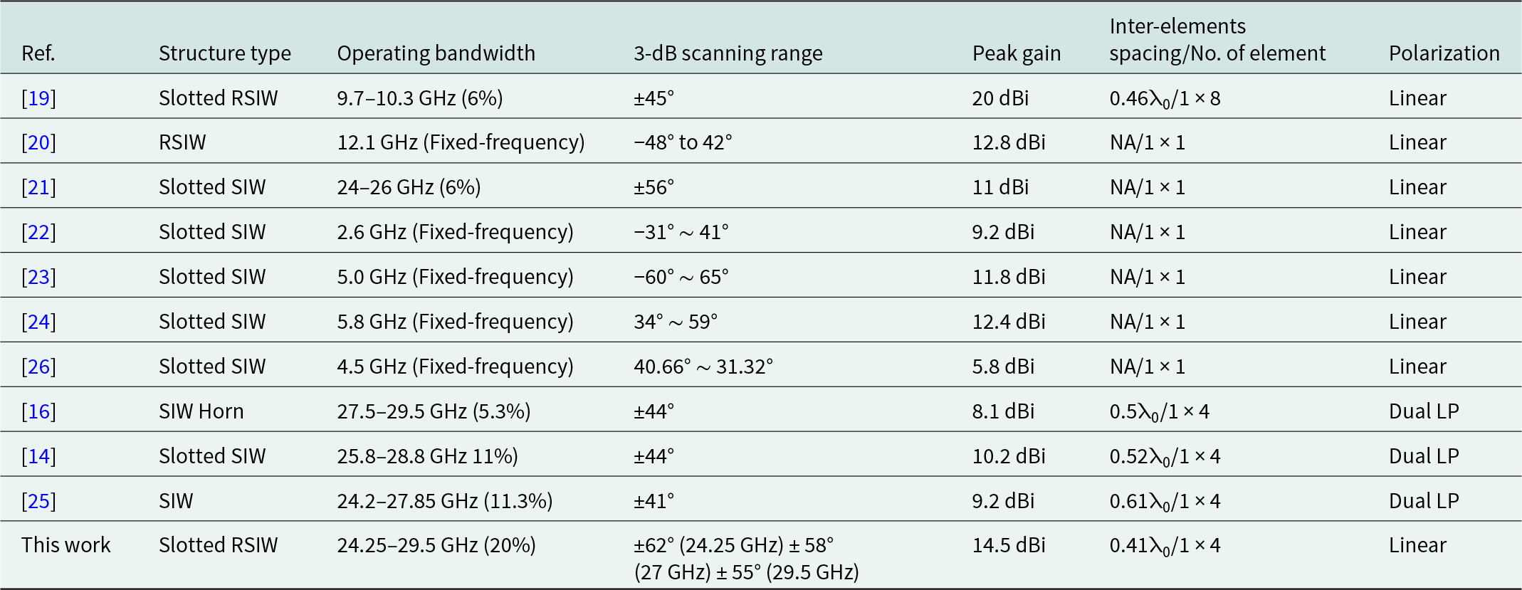
Table 3 compares the proposed mmWave wideband high-gain phased array with its counterparts recently reported in papers [Reference Liu and Yan14, Reference Zhang, Zhao, Wang, Zhang and Pedersen16, Reference Mallahzadeh and Mohammad-Ali-Nezhad19–Reference Lu, Yu, Zhu and Hong25]. Paper [Reference Mallahzadeh and Mohammad-Ali-Nezhad19] features a similar inter-element spacing and higher peak gain, but the proposed antenna still achieves a broader scanning range. The proposed design operates within a ∼20% bandwidth at 24.25–29.5 GHz, which is comparable to the slotted SIW antennas in papers [Reference Serhsouh, Himdi and Lebbar21] and [Reference Liu and Yan14, Reference Zhang, Zhao, Wang, Zhang and Pedersen16, Reference Lu, Yu, Zhu and Hong25], both operating within a similar frequency range. However, the proposed antenna outperforms these counterparts in terms of bandwidth and peak gain, achieving a ∼20% bandwidth, and a peak gain of 14.5 dBi. This is notably higher than the 6% bandwidth and 11 dBi reported in paper [Reference Serhsouh, Himdi and Lebbar21]. At the same time, the inter-element spacing and scanning range is more desirable than reference [Reference Liu and Yan14, Reference Zhang, Zhao, Wang, Zhang and Pedersen16, Reference Lu, Yu, Zhu and Hong25]. When compared to the fixed-frequency antennas in papers [Reference Wei, Wang, Liu, Li and Wang20, Reference Ji, Ge, Wang, Chen and Wu22–Reference Lou, Yang, Qiu, Luo and Gao24, Reference Chen, Zhang, He, Chen and Zhu26], the proposed design demonstrates a clear advantage in terms of bandwidth, as these antennas are limited to specific frequencies without the wideband capabilities. Additionally, the proposed antenna’s peak gain surpasses that of the 5.8–12.8 dBi range in papers [Reference Wei, Wang, Liu, Li and Wang20, Reference Ji, Ge, Wang, Chen and Wu22–Reference Lou, Yang, Qiu, Luo and Gao24, Reference Chen, Zhang, He, Chen and Zhu26], while maintaining a wider scanning range than in papers [Reference Wei, Wang, Liu, Li and Wang20, Reference Ji, Ge, Wang, Chen and Wu22, Reference Lou, Yang, Qiu, Luo and Gao24, Reference Chen, Zhang, He, Chen and Zhu26]. In summary, the proposed slotted RSIW antenna exhibits satisfied performance in terms of wide operating bandwidth, broad scanning range, and high peak gain compared to its counterparts.
Performance comparisons with other reported beam-scanning antennas

This design can be implemented using different multi-layer planar circuit processes, and both LTCC and HDI process are suitable to the design. Although LTCC is adopted in this work and the design based on it has good performance of high radiation efficiency due to the low-loss substrate material, its mass production is costly. The efficiency of the design based on HDI process is relatively poorer, mainly due to the high loss of substrate material, but its mass production cost is quite low. Therefore, HDI can also be adopted to expand the scope of design.
Several limitations still exist. First, regarding the design of the slot antenna subarray, the slot structure is not perfectly symmetrical. This asymmetry affects the cross-polarization level to a certain extent after array assembly. Second, the scanning range is still limited, which less than ±60°a generally requirement for many mmWave terminal applications. Lastly, the adoption of SIW as the transmission line results in relatively high costs and complicated feeding network. Therefore, for future work, research will be carried out on the designing of colinear slot array to solve cross-polarization, broadening the unit beamwidth to enhance the scanning coverage of the phased array antenna. Moreover, improvement on the feeding network, for example reduction of number of feed layers should also be carefully considered.
Conclusion
In this paper, a novel RSIW slot mmWave beam-scanning phased arrays is proposed. The antenna array adopts staggered slot radiating elements and incorporates additional radiation elements on the non-scanning plane to enhance the gain. The LTCC process enables the RSIW slot antenna array to achieve wideband transmission and increasing half-power beamwidth above 106° for the corresponding element. The series-parallel combined feeding network further enhanced the wideband and low loss characteristics of the slot antenna array. By adding isolation slots and metal vias between adjacent array elements, energy coupling between array elements is reduced, further improving isolation below −15 dB and improving scanning angle up to ±7°. As a result, the array exhibits exceptional beam-scanning proficiency with a wide bandwidth of ∼20%, featuring a maximum scanning angle spanning ±62° with minimal gain variations. Throughout this entire operating bandwidth, the scanning angles reaching up to ±55°, and the gain is above 14.5 dBi. The element spacing is finally optimized as 0.41λ0, and the overall dimension of the array antenna is 1.68 × 3.136 × 0.15λ0, which is formed in compact LTCC package. These features show antenna array proposed can be applied to mmWave communication systems.
Funding statement
This work was supported in part by the National Natural Science Foundation of China under Grant 62371141, 62271212, and in part by Guangdong Basic Applied Basic Research Foundation Grant Outstanding Youth Fund Project under Grant 2021B1515020039.
Competing interests
The authors declare that they have no known competing financial interests or personal relationships that could have appeared to influence the work reported in this paper.