Introduction
Lead zirconate titanate (PZT) is a versatile material that possesses piezoelectric, pyroelectric, ferroelectric, and electrostrictive material properties. Since the early development of PZT in the 1950s, the material has become pervasive in a variety of bulk actuator applications and is used in low cost ceramic filters due to its piezoelectric properties.Reference Uchino and Giniewicz1, Reference Fujishima2 It has been explored for infrared radiation (IR) detectors and imagers by utilizing its pyroelectric properties.Reference Kohli, Wuethrich, Brooks, Willing, Forster, Muralt, Setter and Ryser3 Commercially available ferroelectric random access memory (FRAM) technology based on thin-film PZT exploits its ferroelectric properties for non-volatile memory.Reference Udayakumar, Moise, Summerfelt, Boku, Remack, Gertas, Haider, Obeng, Martin, Rodriguez, Shinn, McKerrow, Eliason, Bailey and Fox4–7 However, it is the strong piezoelectric properties of thin-film PZT as exploited in piezoelectric MEMS (piezo MEMS) devices that enable exciting new application spaces such as millimeter-scale robotics.
Purely polar piezoelectric (non-ferroelectric) materials such as AlN and ZnO have been extensively explored in MEMS for sensor and resonator applicationsReference Gerfers, Kohlstadt, Ginsburg, Yuan He, Samara-Rubio, Manoli, Wang and Swart8 (as described in the article by Piazza et al. in this issue). Both materials are directly complementary metal oxide semiconductor (CMOS) process compatible and possess low dielectric constants and low material losses, but modest piezoelectric properties. The commercially successful film bulk acoustic resonator filter technology that resides in most cell phones today relies on thin-film AlN as the piezoelectric transducer material.Reference Ruby, Bradley, Clark, Feld, Jamneala and Kun9, 10 In contrast, PZT materials, especially near the morphotropic phase boundary composition (Zr/Ti = 52/48), where the phase transitions between the tetragonal and rhombohedral ferroelectric phases possess higher dielectric constants and higher mechanical and dielectric losses, also exhibit piezoelectric coefficients and electromechanical coupling factors that are more than an order of magnitude larger than those of the non-ferroelectric materials.Reference Trolier-McKinstry and Muralt11, Reference Muralt, Polcawich and Trolier-McKinstry12 Randomly oriented PZT films exhibit effective thin-film, transverse piezoelectric coefficients e 31,f in the range of –6 to –8 C/m2,10 while 001 textured films with minimal Zr/Ti gradients through the film thickness have recently shown values as high as –18 C/m2.Reference Calame and Muralt13
Piezoelectric actuator properties scale favorably at micron-scale dimensions; actuator force scales with thickness, while flexural stiffness scales with the cube of thickness. This scaling and the high e 31,f of PZT enables piezo MEMS actuators that can achieve very large displacements and/or forces. Furthermore, dc power consumption or power efficiency of piezoelectric actuators is largely determined by the dielectric loss of the material. PZT films typically exhibit dielectric loss values less than 5%, leading to extremely power efficient actuators with low leakage currents. PZT thin films permit the application of large electric fields (∼75–500 kV/cm) while allowing MEMS devices to operate with near CMOS-compatible voltages. For transducer and resonator applications, the quasi-static electromechanical coupling factors are key material properties.Reference Meitzler, Tiersten, Warner, Berlincourt, Coquin and Welsh14 These describe the efficiency with which energy is transduced from one energy domain to another. Applications such as filtering certain cell phone bands can require large coupling factors to achieve the needed filter bandwidth. PZT possesses coupling factors that are far larger than those of AlN and ZnO, and hence can achieve much wider bandwidth filters.
The attractive properties of thin-film PZT have led to an increasing interest in commercializing piezo MEMS technologies. Panasonic Corporation is now offering a thin-film PZT based two-axis gyroscope, and several companies are now marketing PZT MEMS inkjet print-heads.15, 16 Numerous types of other PZT MEMS devices have been demonstrated over the last 20 years, and many of these are described in available reviews on piezo MEMS materials and devices.Reference Muralt, Polcawich and Trolier-McKinstry12, Reference Muralt17–Reference Polcawich, Pulskamp, Ghodssi and Lin19 This article focuses on two specific application areas for PZT MEMS: one represents a nearer term opportunity for commercialization (RF devices) and the other a high-risk but high-payoff, longer term technology (MEMS robotics).
Small-scale robotics
A more recent application area for PZT MEMS is millimeter-scale robotics.Reference Pulskamp, Polcawich and Oldham20 The increased dependence on autonomous systems in various military and commercial applications has motivated the miniaturization of such systems. Smaller platforms will likely be less costly, more portable, and reduce logistical overheads. Extreme miniaturization to the millimeter-scale could provide further benefits in defense applications, including achieving unprecedented levels of stealth and the unique ability to access locations at that scale. In addition, microelectronic and MEMS technologies will permit low-cost manufacturing of these platforms with high levels of integration featuring diverse component functionality (see Figure 1). This will also make it possible, with a modular approach to system design, to field larger and more capable heterogeneous networks of robots.
Notional millimeter-scale robotic systems based on lead zirconate titanate microelectromechanical systems (PZT MEMS) and highly integrated microelectronics. Green indicates PZT MEMS actuators, and the stacked “chips” on the body segments represent other required microelectronic subsystems. The robot design on the left is a hexapod (six-legged)-based flight capable design; the design on the left is a myriapod (many-legged)-based design intended to carry greater payload.

Of course, numerous technical challenges must be overcome to realize this potential. One key challenge is to achieve mobility that is comparable to insects while supporting weight that permits useful system capabilities. For example, for the leg designs of the notional systems illustrated in Figure 1 to achieve the same range and type of motion as insects requires the robot to carry less weight. Supported weight translates to available power and payload capability. Higher performance actuators alleviate this design tradeoff. The capacity of PZT MEMS actuators to generate large displacements and forces efficiently and at low operating voltages uniquely positions the technology to meet this as well as other challenges presented by millimeter-scale robotics.
Actuators
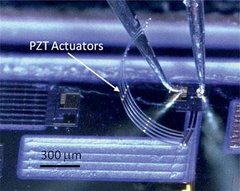
While millimeter-scale autonomous robots may seem like a futuristic concept, the current development of piezo MEMS technologies will enable such systems in the next few years.Reference Pulskamp21 PZT MEMS actuators exhibit large work and power densities with superior power efficiency relative to electrostatic, magnetic, and electrothermal MEMS actuation approaches.Reference Oldham, Pulskamp, Polcawich, Ranade and Dubey22 High power efficiency, intrinsic to piezoelectric transduction, is essential for small-scale robotic applications where available power is a central issue. Additionally, low voltage operation alleviates the challenge of efficient small-scale power conversion.Reference Morgan, Bedair, Pulskamp, Polcawich, Meyer, Dougherty, Lin, Arnold, Bashirullah, Miller and Roosz23 Perhaps most importantly though is the ability of thin-film PZT MEMS actuators to produce very large forces and displacements. For example, the test structure in Figure 2 achieves approximately 150° angular displacement (∼950 μm) at 15 V while consuming less than 1 pW of dc power. Currently, this performance is only achievable with PZT MEMS actuation.
Lead zirconate titanate microelectromechanical systems (PZT MEMS) actuator exhibiting approximately 150º angular displacement (∼950 μm) at 15 V. The test structure is 1.5 mm long and consists of 0.5-μm-thick PZT (52/48) on 1 μm of SiO2.

In contrast to many other actuator technologies, most piezo MEMS actuators feature very simple geometric designs that easily accommodate various displacement amplification schemes. The most ubiquitous of these amplification designs in MEMS is the unimorph “bender.” This structure utilizes the in-plane piezoelectrically induced stress, based on the e 31,fpiezoelectric constant, to create a moment about the neutral axis of the structure to produce flexural displacements. The unimorph converts the large force/small displacements of the piezoelectric layer into smaller forces/larger displacements of the overall structure. This basic configuration has been exploited to achieve various piezo MEMS actuator designs that are applicable to small-scale robots.
Millimeter-scale robots with the range of motion and dexterity of insects will require joint and leg designs similar in structural complexity. This has partly motivated the development of PZT MEMS actuators that can translate and rotate in and about the three fundamental spatial dimensions. Figure 3 illustrates some of the basic piezo MEMS actuator designs that have been developed. Vertical displacements, necessary for the lifting of robotic legs, can be achieved through bending of a vertical unimorph cantilever design (Figure 3a) or through pure vertical translation (Figure 3b) with the design described in Reference 24. In-plane motion can be achieved with PZT MEMS lateral actuators (Figure 3c);Reference Oldham, Pulskamp, Polcawich and Dubey25–Reference Seo, Choi, Lee, Je and Whang27 these devices typically use external flexures (springs) to also produce in-plane rotation. The cascading of the actuators can produce the large in-plane rotations desired for robotic joints.Reference Edamana, Hahn, Pulskamp, Polcawich and Oldham28 Pure out-of-plane rotational actuators (Figure 3d), also based on the simple unimorph, have been developed and can enable more complex robotic joint motions.Reference Pulskamp, Polcawich and Oldham20, Reference Tani, Akamatsu, Yasuda and Toshiyoshi29 Preliminary results have been achieved with three degrees of freedom millimeter-scale leg designs that are based on the integration of some of these actuators (Figure 4).Reference Oldham, Rhee, Ryou, Polcawich and Pulskamp30 However, significant challenges remain in this area, including achieving true biological-like range of motion and dramatic improvements in the load-bearing capability of these robotic joints.
Scanning electron micrographs of example lead zirconate titanate microelectromechanical systems (PZT MEMS)-based actuator designs, including (a) a standard vertical unimorph cantilevered piezo MEMS actuator,Reference Pulskamp, Polcawich and Oldham20 (b) a vertical translational unimorph actuator design and complete actuator platform (inset),Reference Qiu, Pulskamp, Lin, Rhee, Wang, Polcawich and Oldham24 (c) a lateral (in-plane) actuator,Reference Conway, Traina and Kim26 and (d) an out-of-plane rotational actuator design.Reference Tani, Akamatsu, Yasuda and Toshiyoshi29 The red arrows indicate the direction of motion.

Micrograph of lead zirconate titanate microelectromechanical systems (PZT MEMS) three degrees-of-freedom robotic leg design based on the work in Reference 28. Joint #1 is a vertical unimorph actuator, and joints #2 and #3 are series cascaded lateral actuators.

Ultrasonic motors
Non-contact, flexure based actuators are not the only class of piezo MEMS actuators applicable to millimeter-scale robotics. One of the earliest papers to discuss insect-scale autonomous robotsReference Flynn, Tavrow, Bart, Brooks, Ehrlich, Udayakmar and Cross31 described the need for thin-film PZT based ultrasonic motors, which utilize vibrations at frequencies above the audible range to create motion. Traveling wave ultrasonic motors (TWUMs) based on bulk PZT have been successfully commercialized for a variety of applications, including auto focus cameras and biomedical instruments.Reference Ueha and Tomikawa32 Further miniaturization beyond the tens to hundreds of millimeters in diameter of current TWUMs is attractive because they offer a low power, compact mechanism to achieve large torques at low speeds without gears, while also providing a holding torque with no power input.Reference Uchino33 Despite these benefits, millimeter-scale TWUMs have not been realized because the traditional manufacturing methods are too imprecise. A piezo MEMS approach has enabled high precision structures using photolithographic patterning to create millimeter-scale TWUMs.Reference Smith, Rudy, Polcawich and Devoe34
These motors operate by exciting a traveling wave in a fixed piezoelectric vibrating component, called the stator. This traveling wave causes the surface of the stator to move in an elliptical pattern. This elliptical surface motion of the stator is then coupled, through the friction provided by a preload normal force, to a rotation in the rotor at the peaks of the traveling wave. The piezo MEMS TWUM described in Reference 34 uses 1-μm-thick PZT (52/48) to excite two out-of-phase standing waves in a 3 mm diameter silicon stator. These standing waves combine through superposition to create a wave of constant amplitude that travels about the disc. To achieve this traveling wave, specific electrode configurations that excite orthogonal vibrational resonant mode shapes are required.
The proof-of-concept TWUM reported in Reference 35, shown in Figure 5, consists of two components: a center-fixed stator with thin-film PZT drive actuators and a silicon rotor created using deep reactive ion etching. Although a silicon rotor was used for the proof of concept, the rotor material can be a free parameter, determined either by device optimization or application requirements. Gold wires that are bonded in the center of the stator disc provide electrical signals but also laterally confine the rotor motion. The proof of concept motor exhibits the low power capabilities of the motor (<10 mW), while also demonstrating rotational speeds up to 2300 RPM. Bulk ultrasonic motors typically consume power in the low Watts range and operate in the 100s of RPM.Reference Ueha and Tomikawa32Figure 5b illustrates the measured motor speed and power consumption of the proof of concept motor. The direction of rotation can be reversed by switching the phase offset of the two drive signals and occurs within approximately 30 ms. The key remaining challenge for piezo MEMS enabled TWUMs is the wafer-scale integration of preloaded rotors and torque coupling mechanisms. While thin-film TWUMs have a number of potential applications beyond mobile robotics, the promising results from this early motor suggest such devices are a potential technology for small-scale rotorcraft and large angle robotic joints.
(a) Micrograph of the proof of concept microelectromechanical systems traveling wave ultrasonic motor. (b) Power consumption and rotational speed as a function of peak actuation voltage shows the low-power, low-voltage capabilities of the proof-of-concept system. Error bars on speed represent standard deviation.Reference Rudy, Smith, DeVoe and Polcawich35 Note: RPM, revolutions per minute.

Insect-inspired flight
PZT actuators are an enabling mobility technology for airborne as well as terrestrial robots. Researchers have demonstrated the use of bulk PZT piezoelectric actuators to generate lift in centimeter-scale insect-inspired flapping wing robots.Reference Wood36 These devices, as with flapping wing insects, produce lift by exploiting unsteady aerodynamic effects associated with complex multiple degrees of freedom wing motion. Utilizing bulk piezoelectric material necessitates the use of a mechanical transmission to convert the very large forces and small displacements of the bulk actuator to the required large displacements of the wing.Reference Avadhunula, Wood, Campolo and Fearing37 In contrast, the use of thin-film PZT piezo MEMS allows the large wing displacements to be produced directly.Reference Bronson, Pulskamp, Polcawich, Kronigner and Wetzel38 Previous work has demonstrated the use of thin-film PZT MEMS actuators to directly drive the stroke (or flapping) and pitch (or rotation) degrees of freedom at angular displacements that are comparable to what insects utilize to fly.Reference Pulskamp, Smith, Polcawich, Kroninger and Wetzel39 The design shown in Figure 6 includes two orthogonal PZT MEMS unimorph cantilever actuators that independently actuate the stroke and pitch degrees of freedom of the attached microfabricated two millimeter long wing. The Au venation pattern stiffens the wing to allow higher frequency (and hence higher lift) resonant operation of the stroke actuator. These thin-film devices using ∼0.5 μm PZT (52/48) thin films have demonstrated 120° of stroke amplitude at 20 V (see Figure 6 inset) and 45° of pitch amplitude at 20 V at biologically comparable frequencies.
Image of finite element modal analysis of desired vibrational mode of wing and actuators with inset showing measured dynamic stroke amplitude versus voltage based on the work in Reference 39. The displacement is plotted in % of peak displacement.

Aerodynamic lift has been achieved with the designs from Reference 39. Figure 7 shows a test platform consisting of two wings attached to a thin-film body structure that is suspended from a silicon chip with an integrated micro-fabricated tether. The tether provides both the mechanical support and the electrical interconnects needed to actuate the device. When the wing actuators are driven at small displacements, the structure merely vibrates. However, when operated at the intended resonant frequency, the generated aerodynamic lift causes the structure to statically displace vertically. The lift was extracted from the measured displacements and the suspension’s finite element modeled spring constant and was determined to be 0.4 μN. This compares well to the expected aerodynamic lift of 0.5 μN, based on quasi-steady aerodynamic models that explain insect flight.Reference Ellington40 While these force values and the corresponding supported mass are quite modest, the validated models predict system-viable millimeter-scale flapping wing robots with previously demonstrated performance and slightly larger wing designs. It is expected that such a PZT MEMS approach could enable 30 mg robots that could fly up to an hour on thin-film battery power alone.Reference Pulskamp21 Numerous technical challenges, such as the integration of power and control, must be overcome to realize such systems, but the next key milestone will be the demonstration of untethered flight.
Optical micrograph of a millimeter-scale flapping dual-wing test platform atop a US 10 cent coin; based on the work in Reference 39. This structure utilized integrated lead zirconate titanate microelectromechanical systems (PZT MEMS) actuators to successfully achieve aerodynamic lift. Each wing is approximately 2 mm long. A mechanical/electrical tether supports the structure from a silicon die.

Radio frequency and electronic devices
The development of many RF systems today (cell phones, radios, and radar) is driven by the challenging requirement to simultaneously realize higher performance, increased functionality, and reduced system cost. In many cases, piezo MEMS RF devices can uniquely meet the demand for higher performance and higher levels of integration.Reference Piazza, Stepanou and Pisano41 The low-voltage and large force/displacement capability of PZT MEMS actuators enable very high performance switches. The attributes are so significant that further miniaturized PZT MEMS switches are being developed for low power mechanical logic applications in addition to RF switching. Another issue facing RF systems is the continued growth of wireless technologies that exacerbates the crowding of the RF spectrum. Consequently, future RF communication systems will likely rely on greater numbers of integrated high selectivity filter banks. The large electromechanical coupling factors of thin-film PZT and the integration potential of MEMS allows for numerous compact and monolithically integrated high performance and wide bandwidth filters on the same chip. Moreover, the large coefficients of PZT thin films have led to new MEMS resonator applications such as high power density electromechanical power converters.Reference Bedair, Pulskamp, Morgan and Polcawich42
RF MEMS switches
The RF switch or relay is fundamental to most RF circuits and systems. RF MEMS switches have been of interest for their low insertion loss, low power consumption, and high linearity. Commercially available switches/relays from Radant MEMS,43 WiSpry,44 Omron,45 and a few others all utilize electrostatic actuation for their operation with operating voltages in excess of 30 volts. PZT-based piezo MEMS relays offer several advantages over those available currently, including large contact and restoring forces, while maintaining high RF isolation and low actuation voltages that are commensurate with available control voltages.
Switches based on PZT MEMS actuators have been under development for the past decade, with most efforts utilizing unimorph cantilever actuators to provide the physical displacement of a contact pad to open/close the relay.Reference Gross, Tadigadapa, Jackson, Trolier-McKinstry and Zhang46–Reference Polcawich, Judy, Pulskamp, Trolier-McKinstry and Dubey49 Earlier research demonstrated that piezo MEMS switches can be fabricated, operated at voltages as low as a few volts, operate consistently across a wide temperature range, and achieve both low insertion loss and high isolation from dc to 10s GHz. Furthermore, individual PZT RF MEMS single input (pole), 4 output (throw) switches were integrated with liquid crystal polymer substrates to demonstrate an extremely compact, low loss phase shifter.Reference Chung, Polcawich, Judy, Pulskamp and Papapolymerou50
However, these devices exhibited limited cycle reliability. This is due in part to the limited reported data on switches integrated with hermetic packaging technologies. The other key factor was the limited contact force and restoring forces generated in these devices, typically less than 50 μN for each. More recently, design optimization has resulted in the change from an elastic layer using combinations of SiO2 and Si3N4 to single crystal silicon to using thicker films for both the elastic layer and PZT layers. These changes were implemented while maintaining many of the attractive aspects of the early switch design and performance parameters, including actuation voltage, device size, and temperature stability. Recent publicationsReference Ivanov, Pulskamp, Polcawich and Proie51, Reference Ivanov, Proie, Pulskamp, Polcawich and Zaghloul52 have reported switches with 700 μN contact and restoring forces with unpackaged cycle lifetimes exceeding 100 million cycles before the onset of a single failure. These cycle lifetimes compare well with those previously reported in the literature for other unpackaged MEMS switches. A hermetic package is required for final device operation in the millions or billions of cycles depending on final application of use.
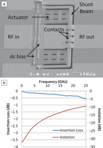
An example PZT MEMS RF shunt switch is shown in Figure 8a. The actuators, which lie in the gap of a co-planar waveguide transmission, bend upward upon application of a voltage resulting in the RF signal being shunted to ground via electrical traces that reside on the outside of the actuators. This device exhibits an insertion loss of less than 0.3 dB from dc to 20 GHz in the open state, while achieving better than 20 dB of isolation across that same frequency band in the closed state (∼15V) (see Figure 8b).
(a) Scanning electron micrograph of a lead zirconate titanate radio frequency (RF) microelectromechanical systems shunt switch and (b) plot of switch insertion loss and isolation.Reference Ivanov, Pulskamp, Polcawich and Proie51

For PZT-based switches, continued improvements to both series and shunt switches and integration with high performance packaging will result in a technology that is attractive for many RF systems. Recently, Advantest has announced the pending release of a piezo MEMS RF relay that would be the first commercially available relay using piezoelectric actuation.53 The ability to simultaneously achieve low voltage operation and high contact/restoring forces enables a switch technology that can be easily inserted into cellular phones for mode switching, phase shifters for phased array radar systems, and relays for automated test equipment.
Mechanical logic
The demand for improved battery lifetimes and further miniaturization of portable consumer electronics is encouraging the development of more energy efficient technologies. For digital circuits, the ultimate in low power integrated circuits is achieved through a subthreshold mode of operation (allows for low voltage) at the cost of reduced speed. Additionally, as devices continue to scale to smaller dimensions and attempt to maintain acceptable on-state drain current levels, static power has significantly increased to the point where it is now comparable to the dynamic power consumed.54
Relative to conventional metal oxide semiconductor field-effect transistors (MOSFETs), an alternative approach to minimizing energy per operation is to utilize mechanical relays to enable zero static power consumption (i.e., off-state power). The first demonstration of MEMS mechanical logic, digital logic elements realized entirely with MEMS relays, used PZT thin-film cantilever actuators to realize a series of logic units, including an inverter, a NAND (Not AND) gate, and a ring oscillator.Reference Judy, Polcawich and Pulskamp55 More recently, a PZT MEMS single-pole, double-throw relay was developed.Reference Proie, Polcawich, Pulskamp, Ivanov and Zaghloul56 The relay, shown in Figure 9a, uses PZT vertical unimorph actuators to control two sets of complementary electrical contacts: a normally open and a normally closed contact set. When open, a contact set has an air gap—nominally 200 nm—separating the contacts and preventing the flow of parasitic leakage currents. When closed, a low resistance Au-to-Ru (or RuOx) contact forms.
(a) Optical micrograph of the mechanical logic relay indicating the two states of operation and (b) current–voltage characteristics demonstrating a sub-2 mV/decade slope during the switching event.Reference Proie, Polcawich, Pulskamp, Ivanov and Zaghloul56 A 1 μA current limit was used for the measurement. Note: NO, normally open; NC, normally closed.

From a dynamic power perspective, the low resistance contacts, coupled with large displacements by the PZT actuator, enable turn-on current–voltage (I–V) slopes significantly sharper than those achievable by MOSFETs. Measured results, shown in Figure 9b, indicate that the slope is less than 2 mV/decade (compared to 60 mV/decade for MOSFETsReference McFarland and Flynn57). Additionally, due to the large air gap that eliminates leakage in the off-state, the switching voltage to achieve an on-state current to off-state current ratio of 105 is about a third of the 300 mV in a theoretically optimal MOSFET device.Reference McFarland and Flynn57 Static power consumption similarly benefits from the PZT-enabled relays. When the normally closed contact is closed, no voltage is required, which completely eliminates actuator leakage in that state. The result is a relay that is over three orders of magnitude lower in leakage than any CMOS technology node.
Devices have demonstrated dynamic switching energies of 500 fJ per relay per transition and propagation delays of under 100 ns.Reference Proie, Polcawich, Pulskamp, Ivanov and Zaghloul56 Measurements showed that the relays were operational from −55°C to 125°C, capable of handling up to 40 V hot-switched across their contacts, and have unpackaged cycling lifetimes over 107 cycles in lab air. Fabricated devices have been used to realize all of the logic elements (e.g., combination logic, memory, and an analog to digital interface) necessary to create a complete MEMS microcontroller. One such example, the clock signal generation circuit, is shown in Figure 10. This type of circuit is composed of a free-running relaxation oscillator that is then “restored” to a square wave via a buffer element. Ongoing efforts are focused on integrating larger scale circuit elements to demonstrate low power, radiation tolerant, and mechanical microcontroller technology.
(a) Optical micrograph of a mechanical logic clock generation circuit. (b) Measured results showing a 10 kHz clock signal generated from a fixed, dc input.Reference Proie, Polcawich, Pulskamp, Ivanov and Zaghloul56

Resonators
Although PZT has had a long and successful history as a bulk material for ceramic resonators,Reference Fujishima2 there are challenges associated with its use in high frequency resonant devices for RF communication applications. These include mechanical and dielectric losses at high frequencies as well as the temperature stability of the dielectric, ferroelectric, and piezoelectric properties. PZT was explored as a possible film bulk acoustic resonator transducer material;Reference Larson, Gilbert and Xu58 but at the time, the lower mechanical losses in AlN outweighed the advantages of stronger coupling. Despite these challenges, the strong piezoelectric properties and high electromechanical coupling factors enable both wide-bandwidth and low-motional resistance resonators.
Additionally, the high-field ferroelectric response permits the switching-on and -off of the resonant response as well as frequency trimming needed to overcome process-induced device variations. The mechanical losses of the PZT can also be mitigated by the introduction of a high-quality factor material such as silicon; though the introduction of such a high-Q (Q is the quality factor) material poses a trade with the device electromechanical coupling factor and, therefore, ultimate filter bandwidth.
Work is ongoing to exploit the strong piezoelectric properties of PZT, and a number of advances have been made with PZT-on-silicon RF-MEMS resonators.Reference Pulskamp, Bedair, Polcawich, Judy and Bhave59 A low insertion loss of 2.1 dB and very low motional resistance (8 Ω) was recently demonstrated in a device using 0.5 μm PZT(52/48) on 2 μm Si at 15 MHz (see Figure 11).Reference Bedair, Pulskamp, Polcawich, Judy, Gillon, Bhave and Morgan60 Tunable PZT-resonator notch filters, which remove particular frequencies instead of only passing those frequencies as with a typical “pass-band” filter, have achieved rejection levels exceeding 109 dB through current cancellation techniques.Reference Bedair, Judy, Pulskamp, Polcawich, Gillion, Hwang and Bhave61 Additionally, PZT resonators and PZT switches were monolithically integrated in one of the first all-RF-MEMS switchable filter banks.Reference Pulskamp, Judy, Polcawich, Kaul, Chandrahalim and Bhave62 Furthermore, recent advances in numerical modeling and design have enabled, for the first time, the use of arbitrary vibrational modes in arbitrary resonator geometries by determining the proper electrode designs (see Figure 12).Reference Pulskamp, Bedair, Polcawich, Smith, Martin, Power and Bhave63 With this technique, a low insertion loss of −6 dB at 70 MHz was demonstrated in a disc resonator using 0.5 μm PZT (52/48) on 10 μm Si driven in a harmonic of an out-of-plane flexure mode; a mode previously unexplored in MEMS due to the assumed high losses across all frequencies. This device achieves the same insertion loss as commercially available surface acoustic wave SAW resonators at the same frequency but is several hundred times smaller. These devices are used in a variety of applications, including signal filtering in RF circuits.
(a) Scanning electron micrograph of a two-port, 5th order length-extensional, 15-MHz lead zirconate titanate resonator and (b) the 50-Ω terminated, forward transmission coefficient, S 21, of the resonator under 2, 5, and 10 volt dc biases on both ports.Reference Bedair, Pulskamp, Polcawich, Judy, Gillon, Bhave and Morgan60 The frequency responses for the 0.5 μm lead zirconate titanate (PZT)(52/48) on 2 and 10 μm of silicon devices are shown.

Example disc resonator electrode shaped for a high order out-of-plane flexure mode.Reference Pulskamp, Bedair, Polcawich, Smith, Martin, Power and Bhave63 (a) Optical micrograph of fabricated device; (b) predicted excitation electrode shape; (c) finite element analysis modal analysis plotting the vector sum of displacements (blue indicates zero displacement and values represent % of peak displacement); and (d) predicted detection electrode shape.

One promising application of thin-film PZT-on-silicon resonators is as resonant transformers, as the energy storage element in high-frequency-switched-mode power supplies.Reference Bedair, Pulskamp, Morgan and Polcawich42 Since the conception of the Rosen-type transformer,Reference Rosen64 the first piezoelectric transformer design, bulk piezoelectric transformers have proven to be advantageous over their magnetic counterparts in size, weight, and the absence of electromagnetic interference.Reference Carazo65 Though high electromechanical coupling is desired for a number of reasons, including high power factors in ac:ac transformer circuits, the added silicon as a structural layer within the thin-film PZT transformer can mitigate mechanical loss and provide higher power densities over thin-film, PZT-only implementations. Recent work has shown thin-film piezoelectric PZT-on-silicon transformers with 2:1 open circuit voltage gain (see Figure 13), high efficiency exceeding 60% for the 1:1 transformer case at 15 MHz, and power densities exceeding 1 W/mm3.Reference Bedair, Pulskamp, Polcawich, Judy, Gillon, Bhave and Morgan60 Further improvements in power handling and efficiency are required for insertion into full power converters.
Measured time-domain response of a 15 MHz lead zirconate titanate electromechanical transformer exhibiting a 2.1:1 ac:ac voltage boost.Reference Pulskamp, Bedair, Polcawich, Judy and Bhave59

Conclusions
The strength and power efficiency of electromechanical coupling in (lead zirconate titanate) PZT-based MEMS (microelectromechanical systems) devices has enabled state-of-the-art performance in various actuators and transducers. Thin-film PZT enables large force and displacement generation in piezo MEMS actuators such as (radio frequency) RF switches and ultrasonic motors; efficient transduction in devices such as mechanical logic relays; low voltage operation in actuators such as millimeter-scale robotic wing joints; and low-loss high-coupling in devices such as piezoelectric transformers and RF resonators. PZT MEMS technology is receiving significant attention for RF and small-scale robotic applications for these reasons; however, there are opportunities to exploit these same material and device attributes in many other applications. The next several years will see the continued and expanded development of PZT-based MEMS in these areas as well as in inkjet printer heads, ultrasonic medical imaging, inertial sensors, and energy harvesting.
Acknowledgments
The authors would like to thank their many collaborators, including Drs. Susan Trolier-McKinstry (Pennsylvania State University), Sunil Bhave (Cornell University), Don Devoe (University of Maryland), and Madan Dubey (US Army Research Laboratory). Additionally, the authors thank Brian Power, Joel Martin, and Luz Sanchez for their efforts in piezo MEMS device fabrication.