I. INTRODUCTION
In the recent years, reinforcement of carbon fibers for thermoset polymer materials has formed a very important class of tribo-engineering materials in nonlubricated condition. This is due to the low density of the composite as well as good mechanical and tribological properties that are comparable to or even better than that of many conventional materials. Usually, carbon fiber improved mechanical and tribological properties of epoxy composites.Reference Khun, Zhang, Lim, Yue, Hu and Yang1 Carbon fibers are one of the most favored candidates as reinforcements in tribological purposes due to their ability to carry the main load between the contacting surfaces, as well as the ability to reduce their adhesion to the counterpart and the frictional heat in the contact area during sliding process.Reference Lin, Xie, Sui and Yang2 Furthermore, the short carbon fiber (SCF) is reportedly effective in reducing plowing and tearing of wear.Reference Chang and Friedrich3 Despite these beneficial effects to the tribological behavior of polymer composites, the high-initial cost of carbon fibers is challenging.Reference Akonda, Lawrence and Weager4
Carbon fiber is a valuable commodity, owing to its specific strength, specific modulus, and thermo-physical properties, it would be more imperative to reuse the recycled carbon fiber (rCF) from the growing amount of nondegradability of carbon fiber reinforced polymer (CFRP) composite waste material. Moreover, the final disposal of the CFRP waste is reported as follows: storage, coprocessing, incineration, and landfill.Reference Rodrigues, de Paiva, do Carmo and Botaro5 However, the thermoset CFRP wastes that are sent to landfill are not biodegradable, and thus could pose health and safety risks.Reference Marsh6 Thus, it is favorable to reuse rCFs that are mechanically ground into powdered fillers from CFRP composite waste. The process of grinding up the end-of-life CFRP composite waste material and sending it to landfill and/or for incinerating has been commonly practiced as it has little appeal to industries due to its degraded properties and the existence of epoxy thermosets on the surface of the rCFs. A comprehensive reviewReference Oliveux, Dandy and Leeke7 also stated that reclaimed carbon fibers from high-technology applications cannot be reincorporated in the same applications from which they were recovered. Therefore, to add value of rCFs and its products as composites, surface treatment via cyclic cryogenic treatment is introduced to shell off the epoxy layer as well as to increase the surface roughness of the fibers for better mechanical interlocking between the fibers and the matrix in the composite.Reference Zhang, Zhang and Breidt8 The shelling off of epoxy remnants is crucial as it would deteriorate the performance of composite due to poor bonding with the polymer matrix. The fact is that the properties of a composite are influenced by the interfacial adhesion between fibers and matrix. Favorable interfacial adhesion can efficiently transfer load from matrix to fibers in composites resulting in stronger composites which plays a key role in determining the mechanical properties of the composites.Reference Zhang, Zhang and Breidt8,Reference Dai, Shi, Zhang, Li and Zhang9
The wear performance of a composite is determined by the interfacial adhesion of the fiber/matrix. Therefore, the cyclic cryogenic treatment was introduced to promote strong interfacial bonding between the fibers and the matrix as reported by researchers.Reference Zhang, Zhang and Breidt8,Reference Law, Ahsan, Hairul, Mohamad and Sivarao10 The treatment has proven to shell off remnant of epoxy resin as well as the weak amorphous carbon layer along the rCF surface,Reference Law, Ahsan, Hairul, Mohamad and Sivarao10 leading to increased surface roughness of the fibers that provide more active sites for better adhesion of the fiber with the freshly introduced matrix.Reference Tiwari, Bijwe and Panier11
In previous researches, the wear resistance of epoxy composites reinforced with carbon fibers has been proven to be enhanced with the inclusion of micro- and nanoscale carbon fillers.Reference Abdul12,Reference Zhang, Zarudi and Xiao13 ResearchersReference Chang and Zhang14,Reference Zhang, Zhang and Friedrich15 have reported that the wear behavior of SCF reinforced epoxy composites is mainly dominated by the process of fiber peeling-off in the sequential stages: fiber thinning, fiber cracking, and fiber removal. Carbon fiber thinning is composed of laminated graphite layers that are worn out gradually by breakage of fibril when subjected to solid sliding, and the thermoset matrix is worn out by delamination wear due to accumulated damage. The resultant wear debris causes abrasive wear which develops large friction at interface.Reference Lee, Hwang and Lee16 Suh and SinReference Suh and Sin17 found that the friction increased exponentially as the plowing depth of wear debris increased. Sin et al.Reference Sin, Saka and Suh18 correlated that the abrasive wear coefficient decreased as the abrasive grit diameter decreased. Zhang et al.Reference Zhang, Zhang and Friedrich15 found that the accumulated wear debris in dry sliding of carbon/epoxy composites enhanced the fiber bending followed by fiber breakage.
In the present work, cyclic cryogenic treatment is introduced to treat the surface of mechanically rCFs, to improve the fiber/matrix adhesion strength that will promote strong interfacial bonding between the rCFs and epoxy matrix. It is perceived that the tribological properties can be improved significantly even at rather low filler content if the particles are uniformly dispersed. The major subject of the present work was to evaluate the influence of rCF treatment on the mechanical and tribological properties of epoxy composites. The dry sliding tribology tests were performed at various contact pressures and sliding speed, using a pin-on-disc apparatus. The effect of reinforcements was discussed and supported with scanning electron microscope (SEM) images of worn surfaces.
II. EXPERIMENT
A. Materials
Bisphenol-A and epichlorohydrin as well as modified liquid amines are the epoxy and curing agents, respectively, used as the thermoset polymer matrix material for the present investigations. It has the appearance of a clear liquid, a gel time of 25 min and viscosity in the range of 12–15 Pa s at 25 °C. The microsize reinforcing fibers used is mechanically ground rCFs in the powder form from partially cured plain woven prepreg waste of CFRP composites. The woven carbon prepregs have the resin content of 38–46%.
B. Processing of recycled carbon fibers
The preparation of the rCFs involved the pulverization process through shearing to comminute CFRP woven prepreg waste into powdered form. Then the pulverized rCFs were sieved to separate the sizes of the fiber. For the treatment of rCF, the pulverized rCFs were treated by using cryogenic treatment technique for 25 cycles. In each cycle, the rCFs were immersed in liquid nitrogen for 3 min and then exposed to the room temperature until the rCF temperature reached 22–24 °C. For effective cryogenic treatment of rCFs, the liquid nitrogen was ensured to be at a temperature of −195 °C. After the 25 cycle cyclic cryogenic treatments, the removal of epoxy resin from the surface of the fibers was observed by means of SEM. The characterization of the pulverized as-received (rCF-AR) and treated (rCF-T) rCFs was carried out which includes the average diameter, densities as well as surface energy of the fibers.
C. Fabrication of composite samples
Vacuum casting technique was used for fabricating the composites. Firstly, the materials were homogeneously dispersed by ultrasonication for 10 min, and then the well-mixed composites were vacuum-casted to produce 155 × 18 × 20 mm bar-shaped composites. The composites were then computer numerical control (CNC) machined as indicated in the ASTM G99 for wear testing to form 6 mm diameter cylindrical-shaped samples. Prior to the composite fabrication, epoxy resin, and the carbon fiber either rCFs-AR or rCF-T were preheated in a drying oven at the temperature of 70 °C for at least 4 h to decrease the viscosity of the resin and to provide optimum wetness for the reinforcing materials.
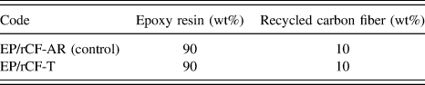
The composition of the composites was listed in Table I. The epoxy (EP) letters correspond to the epoxy resin denomination, while the rCF-AR and rCF-T indicates the as-received and treated rCFs, respectively.
Composition of epoxy composites and their relative codes.

D. Testing
The composites were then characterized for shore hardness, compression test, and tribology test. The compression tests were conducted by using AG-I Universal Testing Machine according to ASTM D695 with the parameter of a constant rate of 1.3 mm/min at room temperature. Two platens were placed on both ends of the test specimen with moving platen on the upper side and fixed platen on the bottom side. The cylindrical test specimens with 6 mm diameter and 8 mm height were compressed between the two platens until the graph showed the first drop, and the test was stopped.
Unlubricated sliding wear experiments were carried out at room temperature on a micro pin-on-disc tribotester apparatus as per ASTM G99 to study the wear behavior of the composite. The counter-body of wear disc is made of EN-31 steel hardened with an average surface roughness of 0.2 µm and hardness of 58–60 HRC (Rockwell hardness in C scale). The wear disc was ensured to be in a good condition with nonrusty surfaces.
The test was carried out under velocity of 0.4, 0.7, and 1.0 m/s, load of 6, 11, and 16 N and a constant sliding distance of 21,580 m. For each composition, the experiment was repeated three times and the specific wear rate value was obtained by taking the average of the three calculated values. After testing, the worn surfaces of the test specimens were observed under SEM and field emission scanning electron microscope. In addition, the average value of coefficient of friction (CoF) was obtained and the surface roughness of the worn out surfaces was measured using portable surface roughness tester.
III. RESULTS AND DISCUSSION
A. Fiber characterization
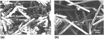
Figure 1 shows SEM micrographs of rCF-ARs and rCF-Ts at 25 cycles. A remarkable difference in the morphology of the fibers can be observed. There are considerable amounts of residual epoxy resin adhering to on the surface of rCF-ARs as shown in Fig. 1(a). Meanwhile, at 25 cycles, SEM image [Fig. 1(b)] shows the almost removal of epoxy residues from the surface of carbon fiber.
SEM images of (a) rCF-AR and (b) rCF-T.

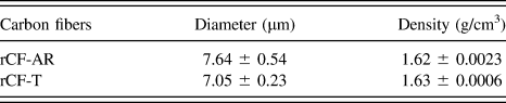
The most considerable explanation of the “shelling off” of epoxy layer is the mismatches in the coefficient of thermal expansion (CTE) between rCF/epoxy that weakened the interface bonding of the fiber and the matrix. At cryogenic temperature, the epoxy layer suffered contraction, while the carbon fiber undergone an axial expansion. After exposed to the room temperature (from −195 to 20 °C), the epoxy layer expand in the transverse direction. As the carbon fiber has lower CTE (12 × 10−6/°C) than the epoxy matrix (70 × 10−6/°C), the fiber mechanically constrains the matrix. This resulted in CTE of composite in transverse direction which is greater than that in the longitudinal direction. Thus, the carbon fiber prevents the matrix from expanding in longitudinal direction and as a result, the matrix is forced to expand more than usual in the transverse direction.Reference Chawla19 The further cyclic contraction at the cryogenic temperature shell off the epoxy layer due to the weakened interface bonding when the shear stresses that arose at the interface bonding of rCF/epoxy exceeded the shear strength of the fiber and the matrix. In addition, as the amorphous carbon is strongly bonded with the epoxy layer, the treatment also cleared the amorphous carbon layer along the fiber surface to various extents, resulting in increase of fiber surface roughness.Reference Zhang, Zhang and Breidt8 An average diameter value of rCF-ARs and 25 rCF-Ts was measured from 20 individual fibers using SEM. The results are presented in Table II. The diameter decreased with the increasing number of cyclic cryogenic treatment which further conformed the shelling off of epoxy layer. As the epoxy layer is bonded to the amorphous carbon layer, the reduction of the fiber diameter was also associated with the removal of weak carbon layer, similarly stated by Zhang et al.Reference Zhang, Zhang and Breidt8
Diameter and density of rCFs.
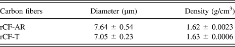
The densities of rCFs were measured using AccuPyc1330 pycnometer (Micromeritics, Norcross, Georgia). The average value of density and its standard deviation were obtained from five measurements. The results are recorded in Table II. It was observed that the density of rCF-AR is lower than the rCF-T. This is because there is residual of epoxy attached to the carbon fiber. As the density of epoxy resin is lower than that of the carbon fiber, the presence of epoxy has attributed to the lower density of rCF-AR. Meanwhile, for rCF-T, the higher density has proven the shelling off of epoxy, in which the carbon fiber has higher density as compared to epoxy resin.
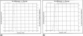
The surface energy of rCF-ARs and rCF-Ts was determined by using Brunauer–Emmett–Teller (BET) analyzer to investigate the adhesion characteristics of the fibers. The adsorption energy of the fiber surface sites was determined through the pore size distributions calculated from nitrogen gas absorption isotherms using the density functional theory method. The results are shown in Figs. 2(a) and 2(b). For optimum adhesion, the adhesion must “wet out” to maximize the contact area and the attractive forces between adhesive and bonding surface. For liquid adhesive to effectively wet out, the surface energy of adhesive must be lower than the substrate to be bonded. Or, the surface energy of the substrate must be raised. In this experiment, the surface energy value of epoxy matrix is lower. Therefore, the lower surface energy of epoxy will “wet out” the higher surface energy surface. When epoxy meets higher surface energy of rCF-T, the contact area with the surface is more enhanced as compared to that of rCF-AR.
Surface energy of (a) rCF-AR and (b) rCF-T carbon fibers.

B. Mechanical properties
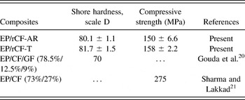
By using Type D Shore Duro-hardness tester (Teclock, Nagano, Japan), the hardness of the epoxy composites was measured. The average hardness value was computed from 10 readings for each composition at different locations. The results are shown in Table III.
Hardness and compressive strength of rCF composites.

It can be seen that hardness of the EP/rCF-T composite is better than that of EP/rCF-AR composite. It indicates that the treated rCFs support most of the load as there was good distribution and strong interfacial bonding of the rCF-T and epoxy matrix, in which there is efficient transfer of the load from the matrix to the reinforcement. Gouda et al.Reference Gouda, Kulkarni, Kurbet and Jawali20 also studied the hardness of carbon fiber and glass fiber reinforced epoxy resin composites and the hardness value of their study is slightly lower than that of present study. In addition, the compression strength data for each composition of composites is also presented in Table III and compares with a study made by Sharma and Lakkad.Reference Sharma and Lakkad21 EP/rCF-T composite shows higher compression strength compared to EP/rCF-AR composite, whereas the compression strength of EP/rCF-T/carbon nanotube (CNT) composite presents better results than the other composites. As the interaction characteristics of a composite significantly influence its performance, an improvement can be observed by EP/rCF-T. This is because of the higher interaction between the treated fiber and the epoxy. The treated fiber is well-adhered to the epoxy matrix contributing to the improvement of compression strength properties.
C. Tribological properties
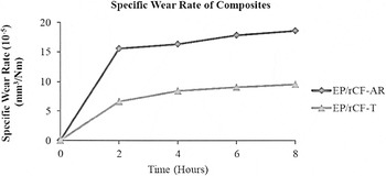
The 2 h interval wear tests were carried to optimize the sliding distance parameter for the tribology test of the composites. The results are presented in Fig. 3. The wear resistance is enhanced by 48.5%. It can be attributed that lower specific wear rate was contributed by the improved interfacial bonding between treated rCFs and epoxy matrix. Meanwhile, the higher wear rate of EP/rCF-AR composite is most probably due to the serious fiber removal as the poor adhesion between the fibers and matrix decreases the interfacial interaction effectiveness. Thus, the wear rate increases because the reinforcement of rCF-ARs could not contribute to wear resistance any more.
Specific wear rate of epoxy composites with a sliding speed of 1 m/s, load of 16 N, and sliding duration of 2, 4, 6, and 8 h.

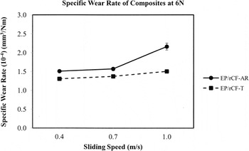
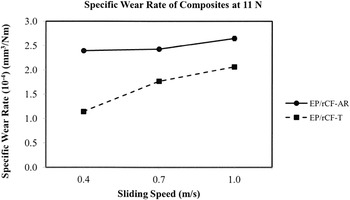
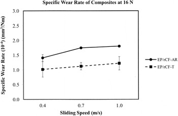
The average specific wear rate values as a function of sliding speed at an applied load of 6, 11, and 16 N are presented in Figs. 4–6.
Specific wear rate of epoxy composites in conjunction with different sliding speeds with an applied load of 6 N and sliding distance of 21,580 m.

Specific wear rate of epoxy composites in conjunction with different sliding speeds with an applied load of 11 N and sliding distance of 21,580 m.

Specific wear rate of epoxy composites in conjunction with different sliding speeds with an applied load of 16 N and sliding distance of 21,580 m.

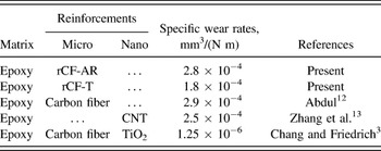
From the graphs, it can be seen that the reinforcement types have an obvious influence on the wear resistance of the epoxy composites. Cyclic cryogenic treated rCF reinforced composite significantly lowered the specific wear rate as compared to rCF-ARs reinforced epoxy composite. For both composites, at a fixed load, wear rate increased with the increase of sliding speed. When the applied load was 11 N, the maximum wear rate was observed for both materials. In previous researches, the wear resistance of composites has been proven to be enhanced with the inclusion of micro- and nanoscale fillers. The attempt has been made by various researches and the results are compared with present research and shown in Table IV. Although wear properties are sensitive on the test condition applied, the present research results agreed well with the results reported by other researches.
Specific wear rate values of different composites.

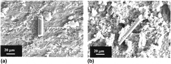
To investigate the different tendencies, the worn out surfaces of composite specimens were observed using a SEM. The SEM images in Fig. 7 confirmed the effective interaction of the treated rCFs with epoxy matrix. The matrix can be seen [Fig. 7(b)] to be adhered to the surface of the fiber, indicating strong interface between the fiber and the matrix as compared to clean pull-out fiber observed in EP/rCF-AR composite [Fig. 7(a)].
SEM images of (a) EP/rCF-AR and (b) EP/rCF-T worn surfaces at 16 N at the sliding speed of 0.7 m/s under a sliding distance of 21,580 m.

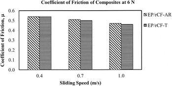
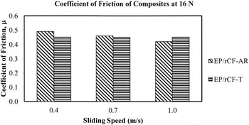
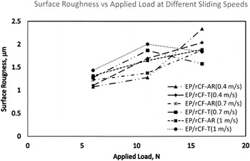
The CoFs, that took the mean values during the steady state of the wear process, are plotted for different sliding speeds at an applied of 6 and 16 N in Figs. 8 and 9, respectively. In addition, the surface roughness of the worn surfaces of composites was measured and the graphs are presented in Fig. 10.
CoF of epoxy composites in conjunction with different sliding speeds with an applied load of 6 N and sliding distance of 21,580 m.

CoF of epoxy composites in conjunction with different sliding speeds with an applied load of 16 N and sliding distance of 21,580 m.

Surface roughness of epoxy composites in conjunction with different sliding speeds (0.4, 0.7, and 1.0 m/s) with the loads of 6, 11, and 16 N and sliding distance of 21,580 m.

The CoF of all the composites was in the range of 0.40–0.55. The lowest value of the CoF was shown by EP/rCF-AR composite for 16 N at 1 m/s whereas the highest value was given in EP/rCF-AR for 6 N at 0.4 m/s. Lower CoF of EP/rCF-AR composite is observed because transfer layer had formed onto the worn surfaces due to localized softening of polymer. The rubbing was changed from metal-on-polymer to polymer-on-polymer during sliding. Thus, the occurrence of adhesion between two smooth surfaces gives low friction via effective interfacial shear strength between two contacting surfaces.Reference Khun, Zhang, Lim, Yue, Hu and Yang1 Meanwhile, for EP/rCF-T, the CoF of 16 N at 0.4 m/s is shown to be lower than that of EP/rCF-AR; 0.45, confirming that the cyclic cryogenic treatment proved to be beneficial in improving the wear resistance of the composites. As the fiber-matrix adhesion improved, the existence of carbon fiber on the surface lessened the direct contact between the rubbing surfaces during sliding and in addition to the self-lubricating effect of carbon fiber, the CoF is reduced. In addition, the surface roughness increases with the increasing load for EP/rCF-AR and EP/rCF-T; the increased surface roughness contributing to the lower value of CoF in this study may attribute to the rapid transfer of debris from the worn surfaces.
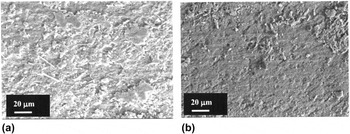
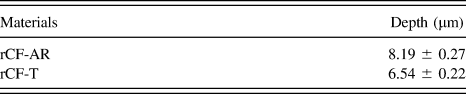
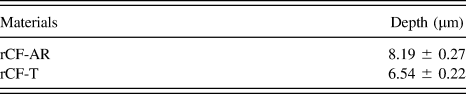
For EP/rCF-AR composites, adhesion wear is the main mechanism responsible for the material loss as shown in Fig. 11(a). It also indicates that the particle/matrix interaction is not strong enough to resist the repeated shear loading during wear test.Reference Oliveux, Dandy and Leeke7 When the breakage of epoxy matrix occurs, the fibers are easily being removed, because there may be lack of local support of the matrix.Reference Chawla19 Consequently, the specific wear rate is higher. Meanwhile, for EP/rCF-T composites, the worn surface shows less damages as shown in Fig. 11(b), implying that a major share of normal load was supported by the fibers. The fibers were always removed gradually and thus contributed to the enhancement of the wear resistance.Reference Zhang and Zhang22 The depth of the peeled-off wear debris measurement further complies with the wear results. The features and depth of wear debris were shown in Fig. 12 and Table V, respectively. The detached peeled-off larger debris of EP/rCF-AR could act as the third body abrasive that increases the wear rate of epoxy composites.
SEM morphologies of worn surfaces of (a) EP/rCF-AR and (b) EP/rCF-T composites at a sliding speed of 1.0 m/s, load of 16 N, and sliding distance of 21,579 m.

SEM micrographs of wear debris of (a) EP/rCF-AR and (b) EP/rCF-T composites.

Wear debris depth measurements.
IV. CONCLUSION
The condition of reinforcements on the mechanical and tribological properties of rCF-AR and rCF-T reinforced epoxy composites have been investigated. From the test results, it was found that the simple and effective cyclic cryogenic treatment of rCFs led to the shelling off of epoxy layer. Also it was found that the reinforcement of rCF-Ts was better than that of the rCF-ARs. After treatment, the interfacial bonding between the treated fibers and the surrounding epoxy matrix had improved, which had a dominant effect on the mechanical and wear behavior of epoxy composites. Thus the treated recycle carbon fiber reinforced composite can be a potential candidate for bearing materials in nonlubricated conditions.
ACKNOWLEDGMENT
The authors acknowledge the financial support from UTeM MyBrain scheme of University Teknikal Malysia (UTeM) for this research.