1. Introduction
With the progress of society and development of technology, robot technology has become more and more widely used in human’s daily life [Reference Garcia, Jimenez, Santos and Armada1]. As the execution part which contacts the robot and the outside world, the performance of the robotic hand directly affects the implementation effect and operational efficiency of the robot to grasp objects [Reference Kashef, Amini and Akbarzadeh2, Reference Zuo, Li and Dong3].
In the past few decades, many multi-finger dexterous hands have been designed, such as Utah/MIT hand [Reference Narasimhan, Siegel, Hollerbach, Biggers and Gerpheide4], Shadow hand [Reference Rothling, Haschke, Steil and Ritter5, Reference Tuffield and Elias6], Robonaut 2 hand [Reference Diftler, Mehling, Abdallah, Radford and Ambrose7, Reference Bridgwater, Ihrke, Diftler, Abdallah and Linn8], DLR-HIT hand [Reference Chen, Lii, Jin, Fan and Liu9, Reference Alessi, Zollo, Lonini, De and Guglielmelli10] and Gifu hand [Reference Alvarez, Lumbier, Gomez, Garrido and Moreno11]. These multi-finger dexterous hands imitate the shape of the human hand, and each degree of freedom is equipped with a driver. Due to multiple sensors assembled inside the robotic hand, these dexterous hands have rich signal interaction and powerful functions [Reference Ozawa and Tahara12]. However, complex structure, comparatively large size and weight, and complicated control system also reduce the flexibility and controllability and increase the research cost of the robotic hand, which is not conducive to large-scale use [Reference Tavakoli, Enes, Santos, Marques and Almeida13].
In order to simplify the control complexity and improve the versatility of the robotic hand, many scholars began to study under-actuated hands, whose advantages are that it uses fewer motors to drive more degrees of freedom (DOFs), which means the overall weight of the mechanism can be lightened and the complexity of the control system can be reduced. At the same time, the under-actuated hand can use its purely mechanical feedback system to envelope the object of different shapes stably without the need of real-time sensor feedback system, so that the under-actuated hand is more suitable for applications in real life and industrial environments [Reference Odhner, Jentoft, Claffee, Corson, Tenzer, Ma, Buehler, Kohout, Howe and Dollar14, Reference Flaieh, Kamil, Bakhy and Jabbar15]. The under-actuated hand has gradually become a research hotspot of the robotic hand.
The under-actuated hand is mainly divided into three grasping modes: coupled grasping mode, self-adaptive grasping mode and parallel grasping mode. The coupled grasping mode imitates the motion posture of the human hand, and multiple phalanxes bend at the same time during the grasping process, which has high efficiency. The coupled hand includes MANUS hand [Reference Pons, Rocon, Ceres, Reynaerts, Saro, Levin and Moorleghem16, Reference Pons, Ceres and Rocon17] and Southampton hand [Reference Johannes, Ecaterina, Pieter, Raoul and Corry18]. In the self-adaptive grasping mode, multiple phalanxes are bent in sequence to envelop the object of different shapes and sizes adaptively. The self-adaptive hand includes SPRING hand [Reference Carrozza, Suppo, Sebastiani, Massa, Vecchi, Lazzarini, Cutkosky and Dario19], Barret hand [Reference Hasan, Vepa, Shaheed and Huijberts20] and SDM hand [Reference Dollar and Howe21, Reference Ma, Odhner and Dollar22]. The parallel grasping mode imitates the pinching action of the human hand, whose principle is similar to the industrial gripper which uses the jigs to clamp the object vertically. Kamakura [Reference Kamakura, Matsuo, Ishii, Mitsuboshi and Miura23] proposed that there are six grasping modes for the human hand and only the parallel grasping mode is suitable for grasping the object on the worktable. By combining two grasping modes, it can also be divided into the coupled and self-adaptive grasping mode and the parallel and self-adaptive grasping mode. The coupled and self-adaptive hand includes Columbia hand [Reference Long, Delpreto, Bhattacharyya, Weisz and Allen24], Caging-based hand [Reference Hirano, Nagaoka and Yoshida25] and CDSA hand [Reference Li, Liu and Zhang26]. The parallel and self-adaptive hand includes SARAH hand [Reference Birglen and Gosselin27, Reference Lamb, Williamson, Heine, Adams and Williams28], Robotiq Hand [Reference Pelliccia, Schumann, Dudczig, Lamonaca, Klimant and Gironimo29], Velo gripper [Reference Ciocarlie, Hicks, Holmberg, Hawke, Schlicht, Gee, Stanford and Bahadur30] and PASA-GB hand [Reference Liang and Zhang31].
The traditional under-actuated hand can meet most applications, but when the finger moves in the parallel grasping mode, the end of the finger will move non-linearly in the vertical direction, whose trajectory is usually an arc, so it is difficult to grasp the object on the worktable. Generally, the under-actuated hand applies the method of combining external sensors and software to compensate for the distance, but it also increases the complexity of the control system. How to use the mechanical structure to eliminate the vertical displacement of the finger has become a concern in the research of the under-actuated hand. Xudong Li et al. added a sliding pair to the base to compensate for the distance [Reference Li and Zhang32]. Chao Luo et al. proposed a VGS hand which compensates for the distance by adding a linear mechanism in the proximal phalanx [Reference Luo and Zhang33]. Eric Zheng et al. uses an eccentric cam fixed to a modified four-bar linkage mechanism to push the shell which is outside of the distal phalanx to compensate for the distance [Reference Zheng and Zhang34].
In this paper, a new configuration of the linear-parallel and self-adaptive under-actuated hand is proposed which uses the five-link mechanism to design the finger and adopts the four-link and sliding base to compensate for the distance between the end of the finger and the worktable. The rest of this paper is arranged as follows: the second part discusses the principle of the linear-parallel and self-adaptive grasping mode and the mechanical structure of the under-actuated hand; the third part analyses the kinematics of the under-actuated hand; the fourth part analyses the contact force of the under-actuated hand; The fifth part develops the prototype of the under-actuated hand and carry out the grasping experiments to verify the motion performance and grasping stability of the under-actuated hand.
2. Design of the under-actuated hand
2.1. Principle of the linear-parallel and self-adaptive grasping mode
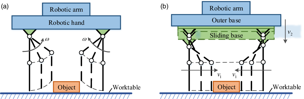
When the under-actuated hand pinches the object on the worktable, the height between the end of the finger and the worktable will change non-linearly, as shown in Fig. 1(a), which makes it difficult for the hand to grasp the object on the worktable, so the hand usually requires the cooperation of sensors and the robotic arm.
Two grasping modes: (a) parallel and self-adaptive grasping mode and (b) linear-parallel and self-adaptive grasping mode.

In order to solve the problem of the non-linearity of the finger, this paper uses the mechanical structure to compensate for the end displacement, as shown in Fig. 1(b). By adding a sliding base in the outer base, when the hand starts to pinch the object on the worktable, the sliding base moves in the outer base to ensure that the end of the finger does not move horizontally, so the hand can pinch the object stably without the help of the control system. This method expands the application range of the under-actuated hand, reduces the dependence on sensors effectively and reduces the complexity of the control system. Need of special note is that the fingers extend outward if the proximal phalanx has an initial joint angle, and this can increase the grasping range of the under-actuated hand.
2.2. Structure of the under-actuated hand
The under-actuated hand is mainly composed of two under-actuated fingers, a sliding base, four compensation mechanisms and an outer base. Two under-actuated fingers have exactly the same structure, and each finger has two joints, where these two joints have a kinematic coupled relationship through the mechanism of the finger. Every finger is controlled by only one motor to realize the under-actuated function. The compensation mechanism can move with the rotation of the proximal phalanx of the finger to implement the end displacement of the finger, without the need of adding additional motors.
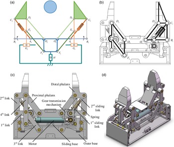
The configuration and mechanical structure of the under-actuated hand are shown in Fig. 2. Among them, the fixed element is the outer base. The line segment
 ${O_1}{D_1}$
and
 ${O_2}{D_2}$
is the proximal phalanx. The line segment
 ${A_1}{B_1}$
and
 ${A_2}{B_2}$
is the first link. The line segment
 ${B_1}{C_1}$
and
 ${B_2}{C_2}$
is the second link. The line segment
 ${C_1}{D_1}$
and
 ${C_2}{D_2}$
is the distal phalanx. The line segment
 ${E_1}{F_1}$
and
 ${E_2}{F_2}$
is the third link. The line segment
 ${D_1}{G_1}$
and
 ${D_2}{G_2}$
is the fourth link. The quadrilateral
 ${O_1}{O_2}{F_1}{F_2}$
is the sliding base. The point
 ${G_1}$
and
 ${G_2}$
of the fourth link and the base form a moving pair and the point
 ${G_1}$
and
 ${G_2}$
can slide in the sliding groove of the outer base. The sliding base and the outer base also form a sliding pair
 $H$
, and the sliding base can move up and down in the outer base. Due to the symmetry of the under-actuated hand, the letter subscript is cancelled for easy analysis, such as
 ${O_1}$
and
 ${O_2}$
is only represented by
 $O$
.
Mechanical design of the hand (a) Configuration diagram. (b) Comparison chart. (c) Mechanical structure. (d) Appearance.

The under-actuated finger adopts the five-link mechanism and the spring to realize the parallel and self-adaptive grasping mode, where the spring can realize the decoupling function of the joints. In order to expand the grasping range, two under-actuated fingers expand outwards in the initial state, as shown in the Fig. 2 (d).
When two phalanxes all do not touch the object, the motor drives the first link to rotate through the gear transmission mechanism. Because of the existence of the spring, the first sliding link and the second sliding link cannot be separated, which means that the first link, the second link, the first sliding link, the second sliding link and the spring seem to be fixed together, and it can be regarded as one part. Since the quadrilateral OACD can be regarded as a parallelogram, when the first link rotates at an angle α, the proximal phalanx also rotates at an angle α, so that the distal phalanx only has a displacement but no rotation relative to the sliding base.
The compensation mechanism adopts the four-link mechanism and the sliding pair mechanism to compensate for the end displacement of the finger.
Because the quadrilateral ODEF also forms a parallelogram and the points D, E, G are collinear, when the proximal phalanx rotates at an angle α, the third link rotates at an angle α, so the rising height of the point D in the vertical direction relative to the sliding seat is equal to the rising height of the point G rising in the vertical direction relative to the sliding seat. But the point G of the fourth link can only slide horizontally in the sliding groove of the outer base, the falling height of the sliding base relative to the outer base in the vertical direction is equal to the rising height of the point D relative to the sliding base in the vertical direction. Therefore, the point D has only a horizontal displacement but no vertical displacement relative to the outer base, which also means that the end of the finger always maintains the same height relative to the worktable.
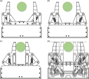
When the distal phalanx touches the object, it cannot rotate due to the obstruction of the object, so it starts to pinch the object. Through the cooperation of two fingers and the compensation mechanism, the movement of the under-actuated hand in linear parallel grasping mode is shown in Fig. 3.
Linear-parallel grasping mode (a) Initial state. (b) 1st state. (c) Parallel state. (d) Superimposed state.

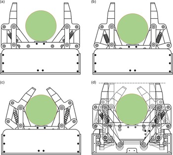
When these two phalanxes all do not touch the object, the under-actuated hand moves in the linear-parallel grasping mode. Once the proximal phalanx touches the object, it cannot rotate due to the obstruction of the object, so the first link pushes the second link and the spring stretches. Finally, the proximal phalanx starts to rotate around the point D until it envelops the object. In the process of the self-adaptive grasping mode, the proximal phalanx does not rotate, so the compensation device also does not work. By the cooperation of two fingers and the compensation mechanism, the movement of the under-actuated hand in self-adaptive grasping mode is shown in Fig. 4.
Self-adaptive grasping mode (a) Initial state. (b) 1st state. (c) Self-adaptive state. (d) Superimposed state.

3. Kinematic analysis of the under-actuated hand
This part uses kinematics to verify the moving feasibility of under-actuated hand theoretically, which mainly includes the kinematics analysis of the under-actuated finger in the parallel grasping mode and the self-adaptive grasping mode respectively, and the kinematics analysis of the compensation mechanism to prove that the mechanism can effectively ensure that the end of the finger does not have longitudinal displacement.
3.1. Kinematics analysis of the fingers in parallel grasping mode
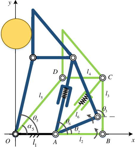
According to the mechanical structure and kinematic characteristics of the under-actuated finger in the parallel grasping mode, the parallel kinematics model is established, as shown in Fig. 5.
Kinematics model of the parallel grasping mode.

In the initial state, the first link is horizontal. Let
 ${\alpha _2},{\alpha _3},{\alpha _4},{\alpha _5},{\alpha _6}$
respectively represent the angle between the first link AB, the second link BC, the line segment CD of the distal phalanx, the proximal phalanx OD, the line segment AC of the combination of the first and the second sliding link, and the x-axis in the initial state,
 ${\theta _2},{\theta _3},{\theta _4},{\theta _5},{\theta _6}$
respectively represent the angle between the first link AB, the second link BC, the line segment CD, the proximal phalanx OD, the line segment AC and the x-axis during the grasping movement. Let
 ${l_1}$
represents the distance between the point O and point A of the sliding base,
 ${l_2},{l_3},{l_4},{l_5},{l_6}$
respectively represents the length of the first link AB, the second link BC, the line segment CD, the proximal phalanx OD, the line segment AC.
When the under-actuated finger starts to grasp the object, it moves in the parallel grasping mode. Due to the action of the spring, the link AC remains unchanged. Because the quadrilateral OACD is a parallelogram mechanism, the link AB pushes the under-actuated finger to move in the parallelogram mechanism, so
 \begin{align}{\theta _5}={\theta _6}\end{align}
The transmission ratio of the gear transmission mechanism is 1, so
 \begin{align}{\omega _5}={\omega _6}={\omega _2}={\omega _m}\end{align}
 \begin{align}{a_5}={a_6}={a_2}={a_m}\end{align}
where,
 ${\omega _5},{\omega _6},{\omega _2},{\omega _m}$
represents the angular velocity of the proximal phalanx, the line segment AC, the first link AB, the motor and
 ${a_5},{a_6},{a_2},{a_m}$
represents the angular acceleration of the proximal phalanx, the line segment AC, the first link AB, the motor.
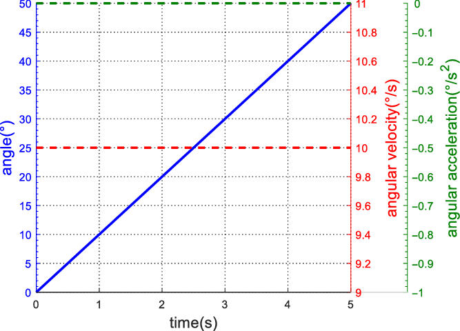
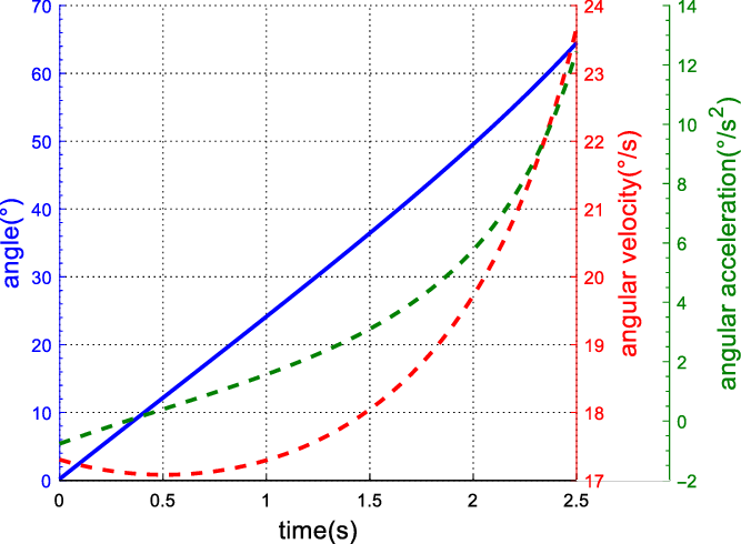
Combining Eq. (1)-(3), the simulation curve of
 $\Delta {\theta _5}$
,
 ${\omega _5}$
,
 ${a_5}$
with respect to time t can be obtained as shown in Fig. 6, which shows that the corresponding angular velocity and angular acceleration curve shape when the corresponding joint is in order to keep the angle increasing at a constant speed.
Simulation diagram of the proximal phalanx.

The distal phalanx has only a relative displacement relative to point O, but for relative rotation, so the path
 ${s_5}$
, speed
 ${v_5}$
and acceleration
 ${a_5}$
of the distal phalanx in the X direction are deduced as
 \begin{align}{s_5}={l_5}\cos {\alpha _5} - {l_5}\cos {\theta _5}\end{align}
 \begin{align}{v_5}={\omega _5}{l_5}\sin {\theta _5}\end{align}
 \begin{align}{a_5}=\omega _5^2{l_5}\cos {\theta _5}\end{align}
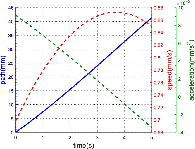
Combining Eq. (4)-(6), the simulation curves of
 ${s_5}$
,
 ${v_5}$
,
 ${a_5}$
with respect to time t are shown in Fig. 7.
Simulation diagram of the distal phalanx.

3.2. Kinematics analysis of the fingers in self-adaptive grasping mode
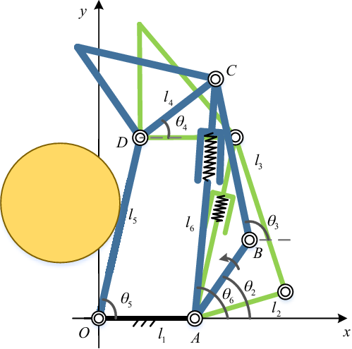
According to the mechanical structure and kinematic characteristics of the under-actuated finger in the self-adaptive grasping mode, the self-adaptive kinematics model is established, as shown in Fig. 8. The characters in Fig. 8 are the same as those described in chapter 3.1.
Kinematic model of the self-adaptive grasping mode.

When the proximal phalanx first touches the object, the finger switches to the self-adaptive grasping mode automatically, and the spring begins to deform and the link AC starts to become longer. Eventually, the first link starts to push the distal phalanx to rotate around point D to envelope object.
By analysing the kinematics of the finger, the closed vector equation of the mechanism is obtained as
 \begin{align}\overrightarrow {AB} +\overrightarrow {BC} =\overrightarrow {AO} + \overrightarrow {OD} + \overrightarrow {DC} \end{align}
According to Euler’s equation,
 \begin{align}\left\{ \begin{array}{l}{l_2}\cos {\theta _2} + {l_3}\cos {\theta _3} = - {l_1} + {l_5}\cos {\theta _5} + {l_4}\cos {\theta _4}\\ \\[-7pt] {l_2}\sin {\theta _2} + {l_3}\sin {\theta _3} = {l_5}\sin {\theta _5} + {l_4}\sin {\theta _4}\end{array} \right.\end{align}
From Eq. (8), the relationship between the angle of the third link
 ${\theta _3}$
and the angle of the distal phalanx
 ${\theta _4}$
is derived.
Calculating the derivative of Eq. (8) with respect to time t, the angular velocity relationship is obtained as
 \begin{align}\left\{ \begin{array}{l} - {l_2}\sin {\theta _2}{\omega _2} - {l_3}\sin {\theta _3}{\omega _3} = - {l_4}\sin {\theta _4}{\omega _4}\\ \\[-7pt] {l_2}\cos {\theta _2}{\omega _2} + {l_3}\cos {\theta _3}{\omega _3} = {l_4}\cos {\theta _4}{\omega _4}\end{array} \right.\end{align}
Write Eq. (9) in matrix form,
 \begin{align}\left[ {\begin{array}{*{20}{c@{\quad}c}}{ - {l_3}\sin {\theta _3}}&{{l_4}\sin {\theta _4}}\\ \\[-7pt]{{l_3}\cos {\theta _3}}&{ - {l_4}\cos {\theta _4}}\end{array}} \right]\left[ {\begin{array}{*{20}{c}}{{\omega _3}}\\ \\[-7pt] {{\omega _4}}\end{array}} \right] = {\omega _2}\left[ {\begin{array}{*{20}{c}}{{l_2}\sin {\theta _2}}\\ \\[-7pt] { - {l_2}\cos {\theta _2}}\end{array}} \right]\end{align}
Combining Eq. (9) and (10), the relationship between the angular velocity of the third link
 ${\omega _3}$
and the angular velocity of the distal phalanx
 ${\omega _4}$
is derived.
Calculating the second derivative of Eq. (8) with respect to time t, the angular acceleration relationship is obtained as
 \begin{align}\left\{ \begin{array}{l} - {l_2}\omega _2^2\cos {\theta _2} - {l_3}(\omega _3^2\cos {\theta _3} + {a_3}\sin {\theta _3}) = - {l_4}(\omega _4^2\cos {\theta _4} + {a_4}\sin {\theta _4})\\ \\[-7pt] - {l_2}\omega _2^2\sin {\theta _2} + {l_3}(\!-\!\omega _3^2\sin {\theta _3} + {a_3}\cos {\theta _3}) = {l_4}(\!-\! \omega _4^2\sin {\theta _4} + {a_4}\cos {\theta _4})\end{array} \right.\end{align}
Write Eq. (11) in matrix form,
 \begin{align}\left[ {\begin{array}{c@{\quad}c}{{l_3}\sin {\theta _3}}&{ - {l_4}\sin {\theta _4}}\\ \\[-7pt] { - {l_3}\cos {\theta _3}}&{{l_4}\cos {\theta _4}}\end{array}} \right]\left[ {\begin{array}{*{20}{c}}{{a_3}}\\ \\[-7pt] {{a_4}}\end{array}} \right] = \left[ {\begin{array}{c@{\quad}c}{ - {l_3}{\omega _3}\cos {\theta _3}}&{{l_4}{\omega _4}\cos {\theta _4}}\\ \\[-7pt] { - {l_3}{\omega _3}\sin {\theta _3}}&{{l_4}{\omega _4}\sin {\theta _4}}\end{array}} \right]\left[ {\begin{array}{*{20}{c}}{{\omega _3}}\\ \\[-7pt] {{\omega _4}}\end{array}} \right] + {\omega _2}\left[ {\begin{array}{*{20}{c}}{ - {l_2}{\omega _2}\cos {\theta _2}}\\ \\[-7pt] { - {l_2}{\omega _2}\cos {\theta _2}}\end{array}} \right] \\[-7pt] \nonumber\end{align}
Combining Eq. (11) and (12), the relationship between the angular acceleration of the third link
 ${a_3}$
and the angular acceleration of the distal phalanx
 ${a_4}$
is derived.
Combining Eq. (7)-(12), the simulation curves of
 ${\theta _4}$
,
 ${\omega _4}$
,
 ${a_4}$
with respect to time t are shown in Fig. 9.
Simulation diagram of the distal phalanx.

3.3. Kinematics analysis of the compensation mechanism
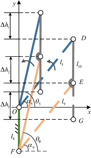
According to the mechanical structure and kinematic characteristics of the compensation mechanism, the kinematic model is established, as shown in Fig. 10, where
 ${\alpha _5},{\alpha _9}$
respectively represent the angle between the proximal phalanx OD, the third link EF and the x-axis in the initial state,
 ${\theta _5},{\theta _9}$
respectively represent the angle between the proximal phalanx OD, the third link EF and the x-axis during the grasping movement,
 ${l_5},{l_{10}}$
represents the length of the proximal distance OD, and the line segment of the fourth link,
 $\Delta {h_1},\Delta {h_2},\Delta {h_3}$
represents the moving distance of the point D, E, G.
Kinematic model of compensation device.

The quadrilateral ODEF forms a parallelogram mechanism, in which the link OF is connected to the sliding base. Due to the parallelogram movement characteristics, when the link OD rotates around the point O, the link EF also rotates at the same angular velocity around point F, then it is deduced
 \begin{align}{\alpha _9}={\alpha _5}\end{align}
 \begin{align}{\theta _9}={\theta _5}\end{align}
The distance of point D and point E in the vertical direction is
 \begin{align}\Delta {h_1} = {l_5}\sin {\theta _5} - {l_5}\sin {\alpha _5}\end{align}
 \begin{align}\Delta {h_2} = {l_9}\sin {\theta _9} - {l_9}\sin {\alpha _9}\end{align}
Point D, E, G are on the same link, so
 \begin{align}\Delta {h_3} = \Delta {h_2} = \Delta {h_1}\end{align}
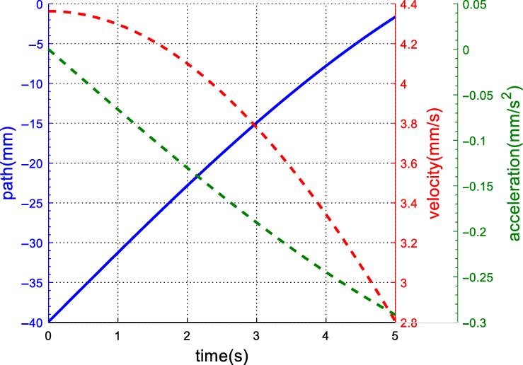
When the under-actuated hand starts to work, the increased height of the proximal phalanx relative to the sliding base is equal to the decreased height of the sliding base relative to the outer base, so that the height of the end of the finger remains unchanged.
 \begin{align}{h_s} = {l_5}\sin {\theta _5} - {l_5}\sin {\alpha _5}\end{align}
 \begin{align}{v_s} = {l_5}\cos {\theta _5}{\omega _5}\end{align}
 \begin{align}{a_s} = {l_5}\cos {\theta _5}{a_5} - {l_5}\sin {\theta _5}\omega _5^2 \\[-3pt] \nonumber\end{align}
Because
 ${\omega _5}={\omega _m}$
,
 ${a_5}={a_m}$
, combining Eq. (18)-(20), the simulation curve of the displacement, velocity and acceleration of the sliding seat in the base with respect to time t is shown in Fig. 11.
Simulation diagram of the sliding base.

4. Contact force analysis of the under-actuated hand
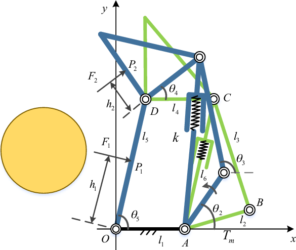
The statics analysis mainly studies the contact force between the two phalanxes of the under-actuated finger and the object to analyse the grasping stability of the under-actuated hand theoretically. In order to simplify the calculation process, the influence of gravity and friction is ignored. The contact force analysis model of the finger is shown in Fig. 12.
Contact force analysis model of the self-adaptive grasping mode.

In Fig. 12,
 ${P_1}$
represents the point of contact between the object and the proximal phalanx.
 ${P_2}$
represents the point of contact between the object and the distal phalanx.
 ${h_1}$
represents the distance between and the proximal joint.
 ${h_2}$
represents the distance between and the distal joint.
 ${F_1}$
represents the force exerted by the object on the proximal finger.
 ${F_2}$
represents the force exerted by the object on the proximal finger.
 ${T_m}$
represents the output torque of the motor.
 $k$
represents the stiffness coefficient of the spring. The other characters in Fig. 12 are the same as those described in chapter 3.2.
Based on the under-actuated finger contact force analysis model [Reference Birglen and Gosselin35], the statics equation of the under-actuated finger is derived according to the principle of virtual work as
 \begin{align}{t^T}\omega = {f^T}V\end{align}
From Eq. (21),
 \begin{align}\left[ {\begin{array}{*{20}{c@{\quad}c}}{ - {T_m}}&{k\Delta {l_6}}\end{array}} \right]\left[ {\begin{array}{*{20}{c}}{{{\dot \theta }_m}}\\ \\[-7pt]{{{\dot l}_6}}\end{array}} \right] = \left[ {\begin{array}{*{20}{c}}{{F_1}} \quad{{F_2}}\end{array}} \right]J\left[ {\begin{array}{*{20}{c}}{{{\dot \theta }_5}}\\ \\[-7pt] {{{\dot \theta }_4}}\end{array}} \right]\end{align}
Where in Eq. (22),
 \begin{align}J = \left[ {\begin{array}{c@{\quad}c}{ - {h_1}}&0\\{{l_5}sin({\theta _4} - {\theta _5})}&{ - {h_2}}\end{array}} \right]\end{align}
According to the vector superposition principle, we get
 \begin{align}\overrightarrow {AO} + \overrightarrow {OD} + \overrightarrow {DC} =\overrightarrow {AB} + \overrightarrow {BC} \end{align}
From Eq. (24),
 \begin{align}l_3^2=({l_2}\cos {\theta _2} + {l_1} - {({l_5}\cos {\theta _5} + {l_4}\cos {\theta _4})^2} + {({l_2}\sin {\theta _2} - {l_5}\sin {\theta _5} - {l_4}\sin {\theta _4})^2}\end{align}
Deriving Eq. (25), the relationship between the angular velocity of the first link and the angular velocity of the distal finger is
 \begin{align}{\dot \theta _2}=\frac{{{l_2}{l_4}\sin ({\theta _2} - {\theta _4})+{l_4}{l_5}\sin ({\theta _4} - {\theta _5}) - {l_1}{l_4}\sin {\theta _4}}}{{{l_2}{l_4}\sin ({\theta _2} - {\theta _4}) + {l_2}{l_5}\sin ({\theta _2} - {\theta _5}) - {l_1}{l_2}\sin {\theta _2}}}{\dot \theta _4}\end{align}
According to the vector superposition principle, we get
 \begin{align}\overrightarrow {AC} =\overrightarrow {AO} + \overrightarrow {OD} + \overrightarrow {DC} {\rm{ }}\end{align}
From the Eq. (27),
 \begin{align}l_6^2={(\!- {l_1} + {l_5}\cos {\theta _5} + {l_4}\cos {\theta _4})^2} + {({l_5}\sin {\theta _5} + {l_4}\sin {\theta _4})^2}\end{align}
Deriving Eq. (28), the relationship between the speed of the spring extension
 ${\dot l_6}$
and the angular velocity of the distal finger
 ${\dot \theta _4}$
is
 \begin{align}{\dot l_6}=\frac{{{l_1}{l_4}\sin {\theta _4} - {l_4}{l_5}\sin ({\theta _4} - {\theta _5})}}{{{l_6}}}{\dot \theta _4}\end{align}
The angular velocity of the first link
 ${\dot \theta _2}$
is equal to the output angular velocity of the motor
 ${\dot \theta _m}$
, so
 \begin{align}\left[ {\begin{array}{*{20}{c}}{{{\dot \theta }_m}}\\ \\[-7pt] {{{\dot l}_6}}\end{array}} \right] = A\left[ {\begin{array}{*{20}{c}}{{{\dot \theta }_5}}\\ \\[-7pt] {{{\dot \theta }_4}}\end{array}} \right]\end{align}
where
 \begin{align}A = \left[ {\begin{array}{*{20}{c@{\quad}c}}1&X\\ \\[-7pt] 0&Y\end{array}} \right]\end{align}
 \begin{align}X=\frac{{{l_2}{l_4}\sin ({\theta _2} - {\theta _4})+{l_4}{l_5}\sin ({\theta _4} - {\theta _5}) - {l_1}{l_4}\sin {\theta _4}}}{{{l_2}{l_4}\sin ({\theta _2} - {\theta _4}) + {l_2}{l_5}\sin ({\theta _2} - {\theta _5}) - {l_1}{l_2}\sin {\theta _2}}}\end{align}
 \begin{align}Y=\frac{{{l_1}{l_4}\sin {\theta _4} - {l_4}{l_5}\sin ({\theta _4} - {\theta _5})}}{{{l_6}}}\\[-8pt] \nonumber\end{align}
From Eq. (21)-(23), the relationship between F 1 and F 2 is deduced as
 \begin{align}\left[ {\begin{array}{*{20}{c}}{{{\dot \theta }_m}}\\ \\[-7pt] {{{\dot l}_6}}\end{array}} \right] = \left[ {\begin{array}{*{20}{c}}{{F_1}} \quad{{F_2}}\end{array}} \right]=\left[ {\begin{array}{*{20}{c}}{\! - {T_m}}\quad {k\Delta {l_6}}\end{array}} \right]A{J^{ - 1}}\end{align}
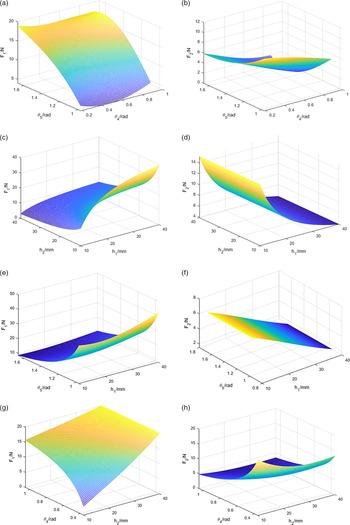
From Eq. (34), using MATLAB to simulate the relationship between
 ${F_1}$
,
 ${F_2}$
and
 ${\theta _4}$
,
 ${\theta _5}$
,
 ${h_1}$
,
 ${h_2}$
. As shown in Figs. 4–16 (a) (b), when
 ${\theta _5}$
increases,
 ${F_1}$
increases, but
 ${\theta _4}$
has little effect on
 ${F_1}$
. when
 ${\theta _4}$
increases,
 ${F_2}$
decreases, but
 ${\theta _5}$
has little effect on
 ${F_2}$
. As shown in Figs. 4–16 (c) (d), when
 ${h_1}$
increases,
 ${F_1}$
increases, and when
 ${h_2}$
increases,
 ${F_1}$
decreases. When
 ${h_1}$
increases,
 ${F_1}$
decreases, and
 ${h_2}$
has little effect on
 ${F_2}$
. As shown in Figs. 4–16 (e) (f), when
 ${\theta _5}$
increases,
 ${F_1}$
decreases, and
 ${h_1}$
has little effect on
 ${F_1}$
. When
 ${h_1}$
increases,
 ${F_1}$
decreases, and
 ${\theta _5}$
has little effect on
 ${F_2}$
. As shown in Figs. 4–16 (e) (f), when
 ${\theta _4}$
increases,
 ${F_1}$
increases, and when
 ${h_2}$
increases,
 ${F_1}$
increases. when
 ${\theta _4}$
increases,
 ${F_1}$
decreases, and when
 ${h_2}$
increases,
 ${F_1}$
decreases.
Relationship between
 ${F_1}$
,
 ${F_2}$
and
 ${\theta _4}$
,
 ${\theta _5}$
,
 ${h_1}$
,
 ${h_2}$
. (a) Relationship between
 ${F_1}$
and
 ${\theta _4}$
,
 ${\theta _5}$
. (b) Relationship between
 ${F_2}$
and
 ${\theta _4}$
,
 ${\theta _5}$
. (c) Relationship between
 ${F_1}$
and
 ${h_1}$
,
 ${h_2}$
. (d) Relationship between
 ${F_2}$
and
 ${h_1}$
,
 ${h_2}$
. (e) Relationship between
 ${F_1}$
and
 ${h_1}$
,
 ${\theta _5}$
. (f) Relationship between
 ${F_2}$
and
 ${h_1}$
,
 ${\theta _5}$
. (g) Relationship between
 ${F_1}$
and
 ${h_2}$
,
 ${\theta _4}$
. (h) Relationship between
 ${F_2}$
and
 ${h_2}$
,
 ${\theta _4}$
.

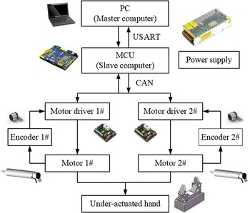
Flowchart of the hardware.

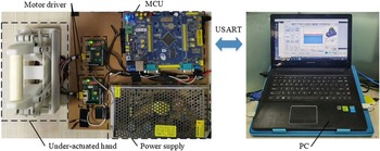
Prototype of the hand.

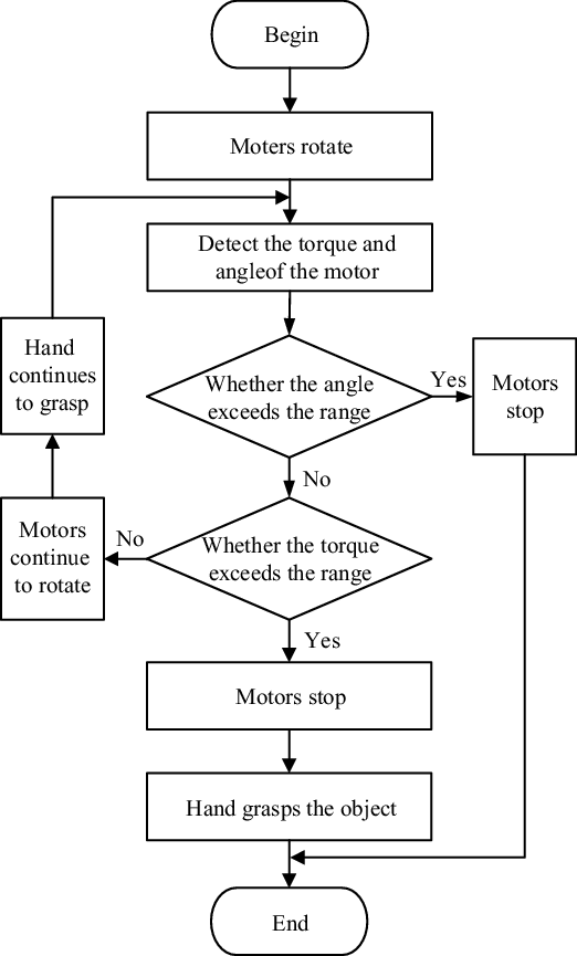
Flowchart of the grasping mode.

5. Prototype development and grasping experiment
5.1. Prototype development
In order to verify the moving performance and grasping stability, the prototype of the under-actuated hand is developed. This paper uses the distributed control method of the master computer and the slave computer, whose flowchart of the hardware is shown in Fig. 14.
The master computer is PC and uses the software Qt to develop the human-computer interaction interface. The slave computer is MCU, the STM32F103ZET6. The motor type is MAXON-B7A1B3C9A03F, which includes a reducer, a DC servo motor and an encoder. The motor driver type is MAXON-EPOS2–24/2 (390438). The master computer and the slave computer adopt the serial communication protocol, and the slave computer and the motor driver adopt the CAN communication protocol. The prototype of the under-actuated hand is shown in Fig. 15.
During the hand grasping the object, MCU monitors the status of the under-actuated hand in real time by collecting the speed, position and torque signals of the motor. If the position of the motor exceeds the range, which means the under-actuated hand exceeds its range of motion, MCU sends the command immediately to stop the motor to protect the hand. When the position is within its range but the torque exceeds predetermined range, it is proved that the under-actuated hand has grasped the object, so the MCU sends command to stop the motor and the under-actuated hand completes the grasping movement. The flowchart of the grasping mode is shown in Fig. 16.
5.2. Grasping experiment
Based on the prototype of the under-actuated hand, this paper carries out a series of grasping experiments to verify the reliability of the hand.
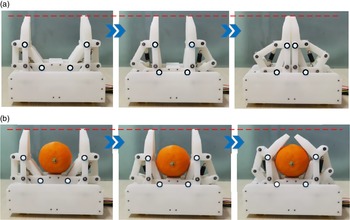
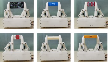
The movement of the linear-parallel grasping mode is shown in Fig. 17(a). When the under-actuated hand works in the linear-parallel grasping mode, the compensation mechanism can compensate the end displacement of the finger, which keeps the distal phalanx move in a straight horizontal line to grasp the object, as shown by the red dotted line in Fig. 17(a). By adding the four-link and sliding base mechanism, the complexity of the control system can be reduced and the application range of the under-actuated hand can be expanded. The experiment of the linear-parallel grasping mode is shown in Fig. 18, which verifies that the hand can pinch different kinds of object effectively.
Movement of the experiment (a) Linear-parallel grasping mode. (b) Self-adaptive grasping mode.

Experiment of the linear-parallel grasping mode.

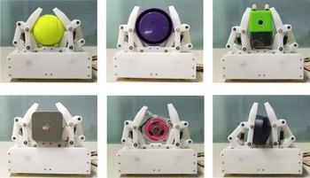
The movement of the self-adaptive grasping mode is shown in Fig. 17(b). When the under-actuated hand does not touch the object, it moves in the linear-parallel grasping mode and the compensation mechanism works. But if the proximal phalanx touches the object, the under-actuated hand will switch to the self-adaptive grasping mode actively according to the shape and size of the object until the object is enveloped. Meanwhile, the compensation mechanism does not work during the self-adaptive grasping mode. The experiment of the linear-parallel grasping mode is shown in Fig. 19, which verifies that the hand can envelop different kinds of object stably.
Experiment of the self-adaptive grasping mode.

6. Conclusions and future works
This paper designs a new configuration of the linear-parallel and self-adaptive under-actuated hand by adopting the four-link and sliding-base mechanism to compensate for the end displacement of the finger. The hand has five DOFs and uses two motors to drive two fingers to grasp the object, which can pinch the object on the worktable and switch the grasping mode according to the shape and size of the object automatically to envelop the object, overcoming the shortcomings of the absence of compensation mechanism as in Fig. 1(a). Mechanical design, kinematics analysis, statics analysis and experimental verification are discussed in this paper. Kinematics analyses the movement trajectory of the hand in various modes and verifies feasibility of the hand. Statics analyses the relationship between the hand and the object, and verifies that the hand has good mechanical properties. By developing the prototype of the under-actuated hand and implementing the grasping experiments, the results show that the under-actuated hand has good motion performance and grasping performance.
In the future, the developed linear-parallel and self-adaptive under-actuated hand will be installed on a robotic arm to further verify its performance and to study the intelligent grasp algorithm improving its intelligence level.
Author Contributions
Jianfeng Li and Mingjie Dong conceived and designed this study. Yuan Kong performed the mechanical design of the mechanism. Jianfeng Li and Yuan Kong conducted the kinematic analysis and contact force analysis. Yuan Kong and Mingjie Dong wrote the paper. Jianfeng Li and Ran Jiao reviewed and edited the manuscript. All authors had read and approved the manuscript.
Competing Interests
The author(s) declare none.
Acknowledgments
This work was supported in part by Beijing Natural Science Foundation under grant No.3204036, in part by the General Program of Science and Technology Development Project of Beijing Municipal Education Commission under Grant No.KM202010005021, in part by the National Natural Science Foundation of China under Grants No.61903011 and in part by the National Key R&D Program of China under Grant No.2018YFB1307004 and 2020YFC2004200.