Introduction
Seamless track is a vital part of modern high-speed trains, and rail welding is a key link in the construction of seamless lines. Flash butt welding (FBW) has become one of the major means of rail welding owing to its good appearance, high strength, and stable welding process [Reference Godefroid, Faria, Cândido and Viana1, Reference Stone, Iwand, Kristan and Lehnhoff2, Reference Zhao, Fan, Liu, Wang and Dong3, Reference Zhang, Li, Ding, Song and Gao4]. FBW is a solid-phase welding technology, which mainly includes two processes: flashing and upsetting. There is no shielding gas during the welding process; hence, it mainly relies on the metal vapor generated at high temperature during the flashing process and the self-oxidation of the high-temperature blasting liquid metal particles to prevent oxidation of the welded joint. Therefore, oxide inclusions are easily formed in the welded joint. If the oxide inclusions remain in the joint after welding, gray spots will be formed and crack sources will be generated, which will seriously affect driving safety [Reference Ichiyama, Ichikawa and Saito5, Reference Zhang, Gao, Niu and Luo6, Reference Shen, Wei, Zhu, Liang, Liang, Jiang and Xiao7, Reference Ozakgul, Piroglu and Caglayan8, Reference Xu, Lu and Shu9].
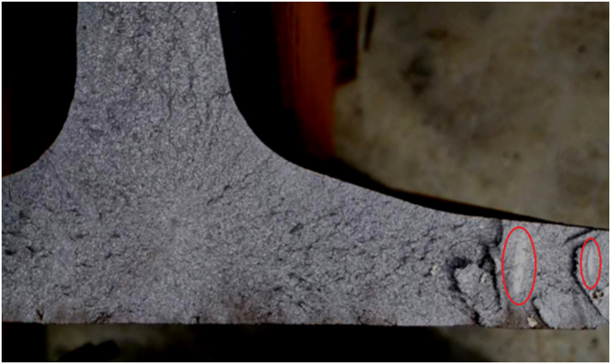
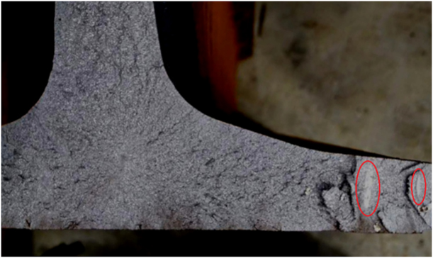
Gray spot is a unique defect of FBW. During the welding process, the silicate inclusions at the weld are gathered, and some of them are distributed on the joint end faces of the welded parts. The rest remain in the craters generated by the liquid-bridge blasting. The former are easily extruded out from the end face with the liquid phase, whereas it is difficult to squeeze out the latter owing to the limitation of the craters and, consequently, gray spots are formed [Reference Zheng, Tian and Wu10, Reference Räsänen and Martikainen11]. As shown in Fig. 1, the gray spots have a flat appearance and their color is distinctly different from that of the base metal. The essence of gray spots is oxide inclusion, except that gray spots are the fracture surfaces of oxide inclusion nucleation [Reference Räsänen and Martikainen11, Reference Ichiyama and Saito12]. According to the formation mechanism of gray spots, there are usually two ways to reduce the incidence of oxides such as gray spots on the joint. The first is to adjust the flashing parameters to fully stabilize the flashing process and avoid air intrusion to prevent the formation of oxide inclusions. The second is to optimize the welding parameters and extrude out the generated gray spot defects using the appropriate temperature field and upsetting process. Considering the operating environment of rail FBW, it is difficult to avoid the generation of gray spots. Therefore, it is meaningful to study the extrusion process of impurities in the upsetting process. Some studies demonstrated that an increase in upset pressure leads to a decrease in the width of the heat-affected zone and the grain size as a result of recrystallization. It was also observed that insufficient upset pressure leads to porosity in the joints [Reference Shajan, Arora, Sharma and Shome13]. Ichiyama et al. [Reference Ichiyama, Ichikawa and Saito5] observed that the joint toughness is better when upsetting with a large current and the specific mechanism was also analyzed. Lu et al. [Reference Lu, Xu, Jiang, Ma and Shu14] observed suitable upsetting allowance is beneficial for extrusion of nonmetallic inclusions in the weld metal. Yu et al. [Reference Yu, Feng, Qin, Zhang and He15] observed that mismatched upsetting parameters would cause a free solidification structure in the rail web and the rail head, which tends to form microcracks. Ziemian et al. [Reference Ziemian, Sharma and Whaley16] observed that the number of inclusions and defects on the end face highly depends on the flashing time and upset dimension. The above studies mainly analyzed the influence of the upsetting process on the joint microstructure, performance, and the number of defects. However, there is no specific study on the extrusion behavior of impurities in the upsetting process. Therefore, it is imperative to investigate the influence of the upsetting process on the extrusion behavior of impurities.
Gray spots on the cross section of the rail flash welded joint.
Generally, two methods can be used to study the effect of the upsetting process on the extrusion behavior of impurities. One is an experimental test, which involves performing FBW experiments through different upsetting processes, and thereafter breaking the joint and observing the extrusion of oxide inclusions such as gray spots in the section [Reference Zhang, Gao, Niu and Luo6, Reference Räsänen and Martikainen11]. However, the experimental method is expensive and time-consuming, and sometimes, it is difficult to identify gray spots on the sample section [Reference Räsänen and Martikainen11]. Another method is the finite element method, which is widely used in welding and other engineering applications owing to its higher calculation accuracy and lower experiment cost, especially in the evaluation of residual stress and temperature field [Reference Zhang, Jiang, Zhao, Wei and Tu17, Reference Ma, Cai, Huang, Deng, Murakawa and Pan18, Reference Kim and Kim19, Reference Lionetto, Pappadà, Buccoliero and Maffezzoli20]. Therefore, this study established a three-dimensional mathematical model of the upsetting process of rail FBW and used the numerical simulation software ABAQUS to analyze the extrusion behavior of impurities with different upsetting parameters.
Simulation results and analysis
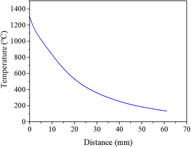
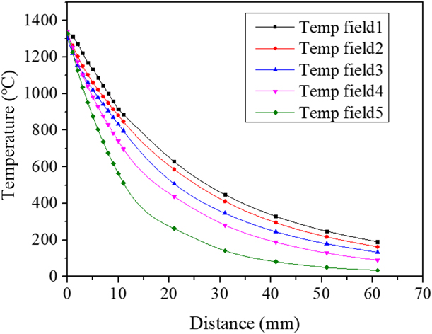
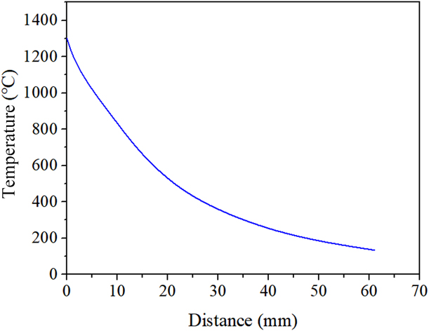
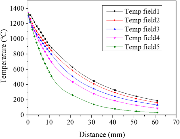
The temperature field distribution of the two rails can be regarded as symmetrical. The initial temperature field is applied to the rail through temperature load according to the characteristics of flashing stage, and the temperature at different distances is recorded with the center of the rail head of the upsetting surface as the origin. The temperature distribution obtained is shown in Fig. 2. To study the deformation of the joint under this temperature field, the upsetting length is set to 10 mm and the upsetting time is set to 1 s.
The temperature distribution of rail top.
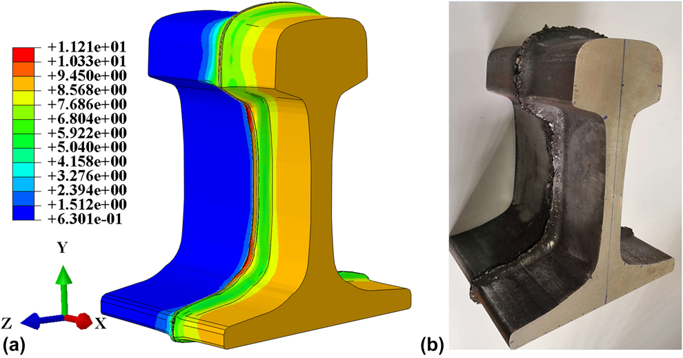
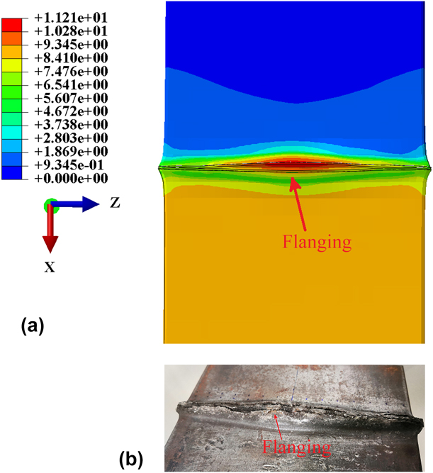
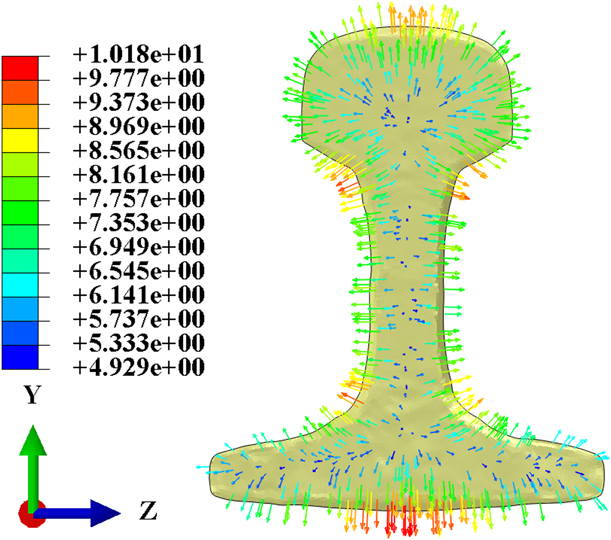
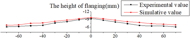
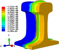
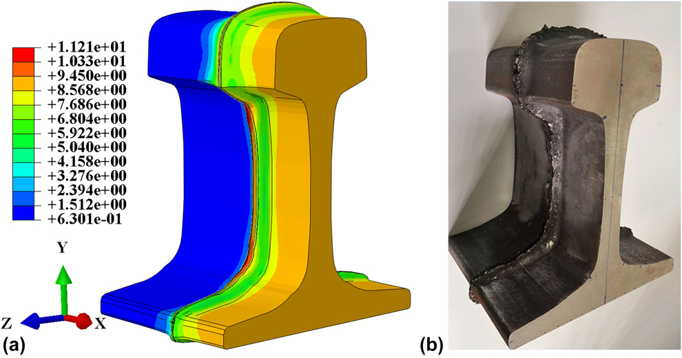
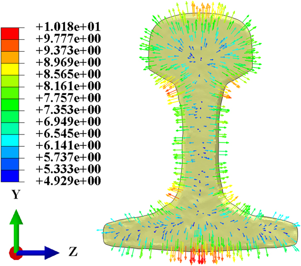
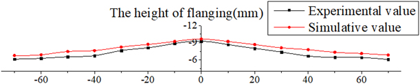
The deformation diagrams of the rail joint obtained in the simulation are shown in Figs. 3(a) and 4(a). After the upsetting stage, the plastic metal with high temperature at the joint is crushed and deformed to form a flanging. It can be observed from Fig. 5 that the areas where the displacement of the plastic metal is large are mainly concentrated in four parts, which are the rail top, the rail bottom, the joint of rail web and rail bottom, and the joint of the rail head and rail web. Furthermore, in this study the actual welding experiment was carried out. The flash parameters were set according to its conventional settings. The upsetting parameters were set as follows: the upsetting length of 10 mm, upsetting time of 1 s, and the total welding time of 118 s. The joint obtained in the experiment is shown in Figs. 3(b) and 4(b), and the deformation results in the joint are consistent with the simulation results. In addition, to ensure the reliability of the model, the height of flanging of the rail bottom shown in Fig. 4 is measured. Considering the midpoint in the Z direction as the origin, the comparison result is shown in Fig. 6. The experimental result is consistent with the trend of the simulation result, which indicates that the model is suitable for the simulation of the upsetting process of rail FBW.
Macroscopic deformation of rail head and rail web: (a) simulation result and (b) actual welded joint.
Macroscopic deformation of rail bottom: (a) simulation result and (b) actual welded joint.

Metal flow direction of rail end face during upsetting.
The height of flanging in experiment and simulation.
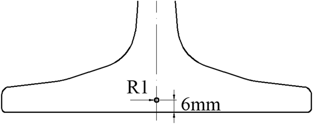
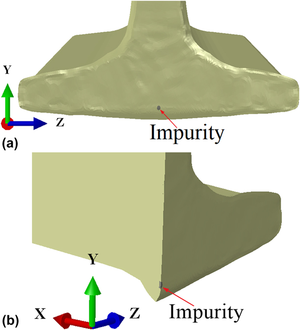
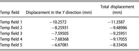
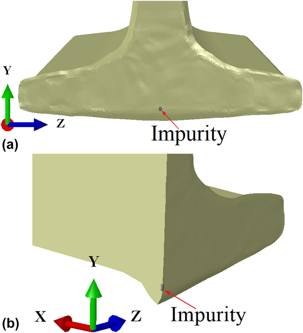
Compared with the experiment, it is feasible to use this model for the upsetting study. For investigating the extrusion of impurities under different processes, a cylindrical body with a thickness of 0.5 mm is embedded in a built-in layer of rail joint to simulate the movement of impurities during the upsetting process. Because the limitation of the crater makes the impurity difficult to move, the movement of the impurity can be regarded as the movement of the crater, so the material properties of the impurity in this paper are the same as rail. As the oxide impurities such as gray spots mainly appear in the areas below the rail web, especially at the base angle and the trigonum [Reference Zheng, Tian and Wu10], the size and position of the impurity are set as shown in Fig. 7. The aforementioned temperature field and upsetting parameters were applied for the upsetting simulation, and the displacement of the impurity at 6 mm from the rail bottom was as shown in Fig. 8. The simulation results show that the flow of plastic metal drives the movement of oxide impurity. The displacement of the highest point of the impurity (7 mm from the rail bottom) in the Y direction is −7.59505 mm, and the total displacement is −9.25951 mm. It can also be observed from the sectional view of Fig. 8(b) that the impurity has been squeezed out from the rail contour along with the flow of the end face metal.
The size and position of the impurity.

The displacement of the impurity: (a) front view and (b) sectional view.
Various process parameters of FBW affect the joint deformation and the extrusion of oxide impurities remaining in the flashing stage. Based on the literature review and the above discussion, the following process parameters have been selected in this study.
Effect of temperature field on impurity extrusion
The temperature field is the primary factor affecting the upsetting process and an appropriate temperature field distribution is the basis of the upsetting process. To study the influence of different temperature fields on the extrusion behavior of impurities, five different temperature gradients were obtained by changing the heating and holding time during heat transfer, as shown in Fig. 9. Under the same upsetting length (10 mm) and upsetting speed (10 mm/s), the displacements of the highest point of impurity in different temperature fields are listed in Table I. It can be observed from the data that the displacement of the impurities is larger as the high-temperature region of the rail is widened, and they are also extruded out from the rail more easily. This is because the high-temperature plastic zone is above 1000 °C for U75V steel [Reference Ren, Ji, Zhou, Yuan, Han and Li21]. The wider the high-temperature region in the temperature field, the more easily the metal is deformed on the upsetting surface and its vicinity, and the likelier it is that the plastic metal extrusion deformation of the rail end face brings out impurities under the action of the upsetting force. Simultaneously, the temperature field before upsetting should match the upsetting process. If the high-temperature plastic zone is too wide, it is easy to cause poor joint formation with a large upsetting force and upsetting length [Reference Ichiyama, Ichikawa and Saito5], which cannot guarantee the joint performance. Therefore, the temperature field distribution before the upsetting process should be considered comprehensively with the upsetting parameters, especially the upsetting length. Furthermore, the high-temperature plastic zone should be widened as much as possible on the basis of satisfying the good shaping and toughness requirements of the rail welded joint.
Temperature distribution of different temperature fields.
The displacements of the highest point of impurity in different temperature fields.

Effect of upsetting speed on impurity extrusion
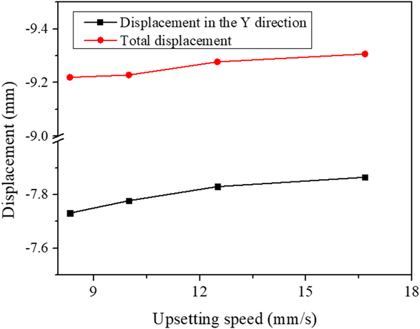
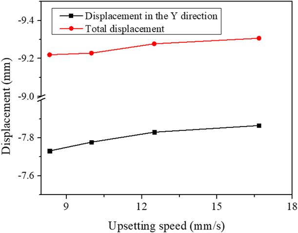
The magnitude of the upsetting speed affects the joint deformation and the extrusion of oxide impurities. Therefore, the simulation of the extrusion of impurities at different upsetting speeds was performed under the same temperature field and the upsetting length of 10 mm. Considering the temperature field 3 as the initial temperature field, the displacements of impurities were calculated when the upsetting time is 0.6 s, 0.8 s, 1 s, and 1.2 s, i.e., the upsetting speed is 16.667 mm/s, 12.5 mm/s, 10 mm/s, and 8.333 mm/s, respectively.
The simulation results are shown in Fig. 10. The higher the upsetting speed, the greater is the displacement of impurities, i.e., the easier is the extrusion of the impurities. Furthermore, an increase in the upsetting speed is beneficial for the rapid healing of the gap between the rails, which avoids the continuous oxidation of the end faces. A significant reduction of the end face temperature is also prevented at a higher upsetting speed, which has an advantageous effect on the recrystallization process of the weld and the strength of the joint. It can also be observed from the curve that the slope becomes smaller when the upsetting speed is greater than 12.5 mm/s, which indicates that the extrusion effect on the impurities becomes no longer evident after the upsetting speed reaches a certain level. Moreover, the requirements for the upsetting hydraulic system are improved when the upsetting speed is too high, which requires a motor with a higher power to drive the oil intake.
The displacements of the highest point of impurity of different upsetting speeds.
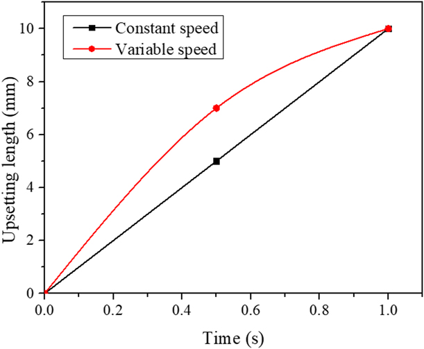
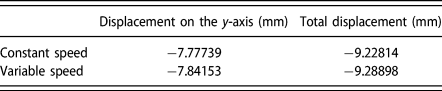
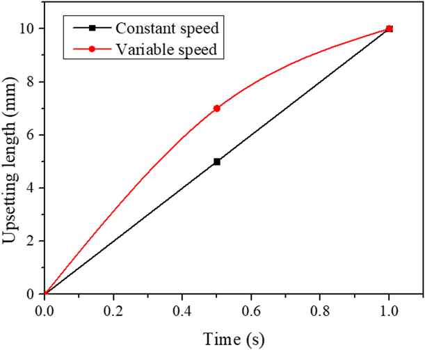
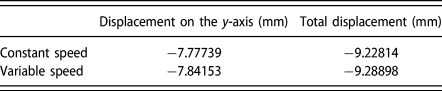
In addition, the influence of constant-speed and variable-speed upsetting on the extrusion of impurities is investigated in this study. As shown in Fig. 11, the upsetting length in both cases is 10 mm. The constant speed is set to 10 mm/s, and variable-speed upsetting adopts the method of slow upsetting after quick upsetting. The calculation results are shown in Table II. It is shown that the displacement of impurities during variable-speed upsetting is larger. As the decline of the rail temperature is fast, the temperature of the rail end face is higher in the initial stage of upsetting, and the rapid upsetting is beneficial for the plastic deformation of the metal. Therefore, in the actual welding process, variable-speed upsetting should be adopted instead of constant-speed upsetting.
Upsetting of constant speed and variable speed.
The displacement of the highest point of impurity of constant speed and variable speed.
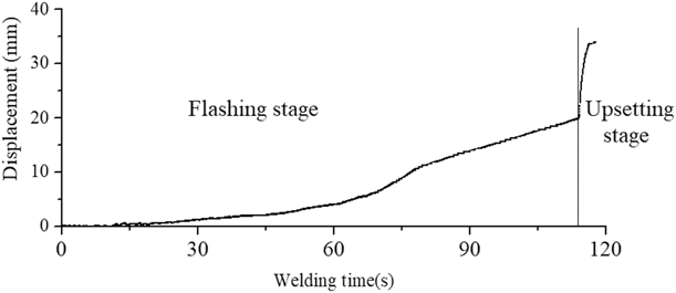
The displacement curve obtained using the UN-150ZB1 flash welder during the welding process is shown in Fig. 12. It can be observed that the actual rail FBW process uses the variable-speed upsetting method. Rapid upsetting is used to close the end face and reduce oxidation in the initial stage of upsetting. The joint forms alternating crystallization by slowing the upsetting speed in the later stage. The simulation results correspond to the actual production, which indirectly proves the reliability of the model. Therefore, using variable-speed upsetting or increasing the speed of the early upsetting can reduce the probability of impurities in the welded joint of the rail under the premise of ensuring the toughness of the joint, thereby improving the quality of the welded joint.
The displacement curve of rail FBW experiment.

Effect of upsetting length on impurity extrusion
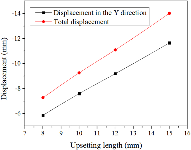
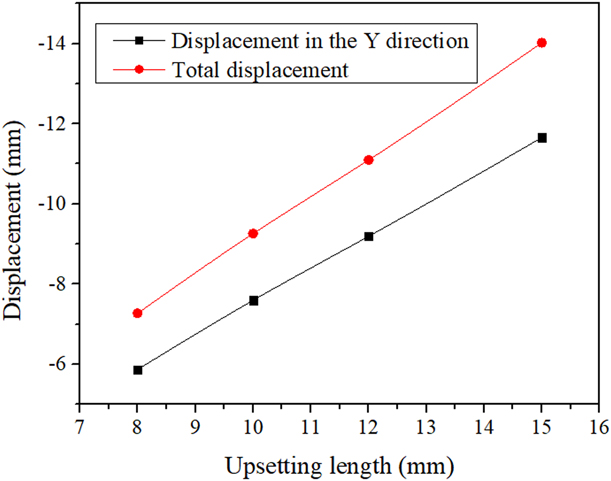
To study the influence of upsetting length on the extrusion of impurities, the temperature field 3 is set as the initial temperature field and the upsetting speed is set as 10 mm/s. The upsetting length is set as 8, 10, 12, and 15 mm. Figure 13 shows the displacement of the highest point of impurity. It can be observed that the displacement of impurity increases linearly with the upsetting length. It shows that increasing the upsetting length is effective for reducing the number of defects such as gray spots, which also confirms the results obtained by Ziemian et al. [Reference Lu, Xu, Jiang, Ma and Shu14, Reference Ziemian, Sharma and Whaley16].
Displacement of impurity in different upsetting length.
However, an excessive upsetting length will cause large lateral deformation and change the metal texture at the joint as the rail is formed by rolling, which will reduce the joint toughness [Reference Ichiyama, Ichikawa and Saito5, Reference Dai, Lv, Tan and Yan22]. The upsetting length is closely related to the temperature field. To achieve a large upsetting length, there must be a wider high-temperature plastic zone. Therefore, the width of the high-temperature plastic zone should be controlled to avoid large lateral deformation caused by the excessive upsetting length and to reduce the joint performance.
Extrusion behavior of impurities at different locations
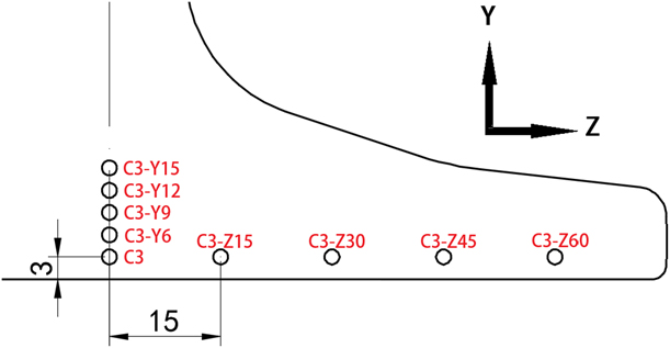
In the rail FBW, oxide impurities such as gray spots mainly appear in the area below the rail web, especially at the base angle and the trigonum. To study the movement of impurities at different positions during the upsetting process, the temperature field 3 is set as the initial temperature field, the upsetting speed is set as 10 mm/s, and the upsetting length is set as 10 mm. The position of the impurities in the model is set as shown in Fig. 14, in which the center of C3 is 3 mm from the rail bottom, and the distance between impurities in the Y direction is 3 mm. The center of all impurities in the Z direction is 3 mm from the rail bottom, and the distance between impurities is 15 mm.
The position of the impurities.
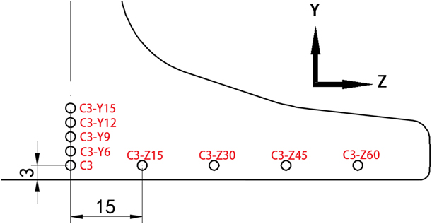
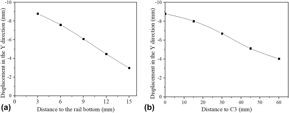
The simulation results are shown in Fig. 15, where the further the distance from the lower surface of the rail in the Y direction [Fig. 15(a)], the smaller is the displacement of the impurity. The displacement of the highest point of C3 in the Y direction is −8.79426 mm, whereas that of C3-Y15 is only −3.06682 mm. This is because the plastic metal at the trigonum of the rail bottom will flow simultaneously toward three surfaces of the rail during upsetting, and the force in the three directions will offset a part or even reach equilibrium, which is not conducive to metal flow and extrusion of impurities. At the center of the trigonum, the protective atmosphere formed by the metal vapor during the flashing process is effective, and the air is difficult to intrude, and hence, the probability of generation of oxide impurities such as gray spots is very low. Therefore, the protection of the flashing process should be strengthened to avoid the formation of oxides in the deep areas. While the areas close to the surface are prone to oxide inclusions, it is also easier to extrude them out.
Displacement of the highest point of impurities at different locations: (a) impurities in the Y direction and (b) impurities in the Z direction.

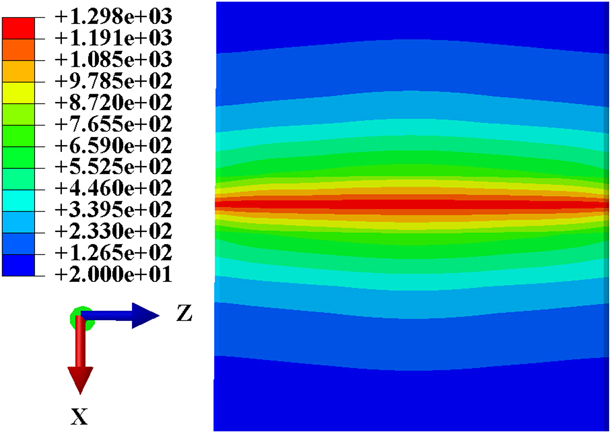
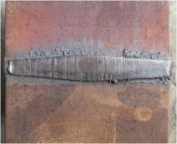
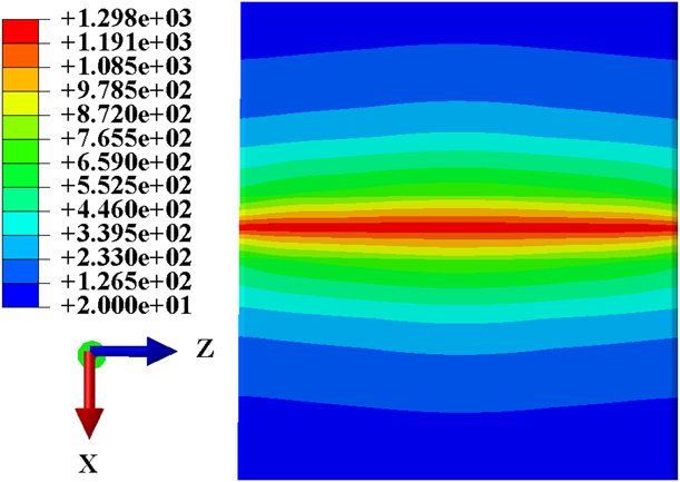
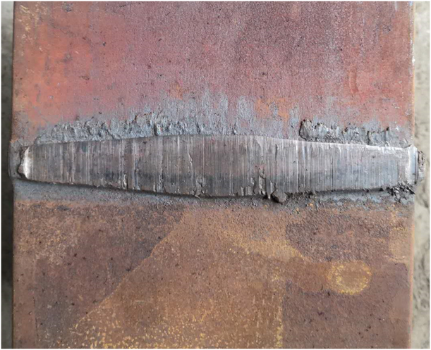
In the Z direction, the displacement of the highest point of impurities is shown in Fig. 15(b). The further the distance from C3, the smaller is the displacement of the impurity. This is mainly due to the difference of temperature fields at the rail bottom. The relative contact areas between the different positions of the rail and air are different because of the particularity of the rail geometry, and the heat dissipation is significantly different. The relative contact areas of air with both sides of the rail bottom are larger, accordingly, the heat dissipation is faster. Therefore, the temperature field formed at the rail bottom is shown in Fig. 16. In the Z direction, the high-temperature range from the center to the sides of the rail bottom is gradually narrowed, and the corresponding high-temperature plastic zone is also narrowed, which is not conducive to the extrusion of impurities. In the experiment, the weld beading of the joint was immediately pushed after welding, and the macroscopic weld profile of the rail bottom was obtained as shown in Fig. 17. It is evident that the weld of the rail bottom is narrowed from the middle to both sides, which indicates that the width of the high-temperature plastic zone is different. The macroscopic weld profile corresponds to the temperature field of the rail bottom of Fig. 16, which also ensures the rationality and reliability of the temperature field.
The temperature field of rail bottom.
The macroscopic weld profile of the rail bottom.
Conclusion
Based on the three-dimensional thermomechanical coupling model of upsetting welding established in this study, the effects of different temperature fields and upsetting parameters on the extrusion behavior of rail FBW were studied. The reliability of the model was verified through experiments. The following conclusions can be drawn:
(1) The numerical model of the upsetting process developed in this study can be used to study the upsetting behavior of rail FBW. The proposed rule for the influence of the upsetting process on the extrusion of residual impurities can guide the parameter debugging of rail FBW process.
(2) During the parameter debugging of rail FBW, increasing the width of the high-temperature plastic zone while matching the appropriate upsetting length is conducive to the extrusion of harmful impurities on the basis of not causing excessive lateral deformation of the joint.
(3) In the case of ensuring the toughness of the joint, using variable-speed upsetting or increasing the speed of the early upsetting also facilitates the extrusion of impurities.
(4) Impurities in areas farther from the surface are not easily extruded out, and hence, it is necessary to ensure that the flashing process is fully stable to achieve protection and avoid the formation of impurities. The areas closer to the rail surface are prone to defects, but the defects can be squeezed out with an appropriate temperature field and upsetting process.
Experimental procedure
An appropriate temperature field and upsetting process directly affect the upsetting deformation and the extrusion behavior of impurities. This study analyzed the effects of temperature field, upsetting speed, and upsetting length on the extrusion of impurities by establishing a three-dimensional finite element model of the upsetting process. The displacement of impurities at different positions on the end face during upsetting was also studied, and the results were compared with the experimental results.
Establishment of finite element model
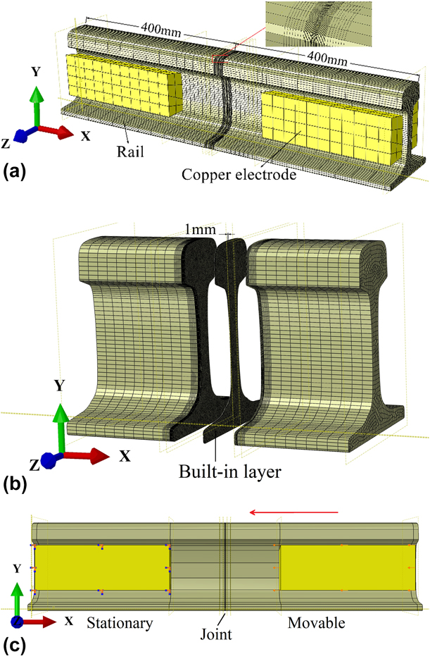
After the flashing process, a very thin liquid layer is formed on the end surface. The oxide inclusions in the liquid metal are easily extruded out during the upsetting process as the fluidity of liquid is excellent. Simultaneously, craters are formed by the liquid-bridge blasting during the flashing process. The craters are solid phase, whose fluidity is not as good as that of the liquid phase. Therefore, it is difficult to squeeze out the oxide inclusions remaining in these craters [Reference Zheng, Tian and Wu10]. Thus, a three-dimensional finite element model of the solid-phase upsetting process is developed, whereas the liquid phase portion is neglected. The model is shown in Fig. 18.
Three-dimensional model of rail upsetting process: (a) three-dimensional overall model, (b) built-in layer, and (c) loading method.
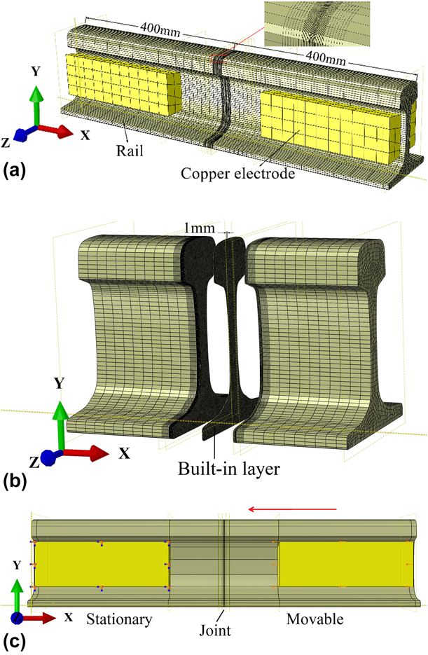
As shown in Fig. 18(a), the total length of each rail is 400 mm in this model. Two pairs of copper electrodes are clamped on both sides of the rail web and 110 mm away from the rail end faces. The large deformation zone is focused on the joint and its vicinity, and hence, finer meshes were designed in these areas, whereas relatively coarser grids were adopted in the region away from the joint. Furthermore, as shown in Fig. 18(b), a solid layer is used to embed gray spots for the upsetting simulation. In this model, three-dimensional eight-node elements are used for analysis in ABAQUS. The continuum model has 198,969 nodes and 166,044 hexahedral solid elements.
The material properties that must be determined in this model are thermal conductivity [mW/(mm °C)], specific heat capacity [mJ/(T °C)], density (T/m3), Poisson’s ratio, and elastic modulus (MPa). As the upsetting process is a deformation process at high temperature, the material properties use temperature-dependent data. Furthermore, the deformation of the rail is closely related to the temperature and the upsetting speed. The Johnson–Cook model is a classic empirical constitutive model proposed by Johnson and Cook in 1983 [Reference McClain, Batzer and Maldonado23]. The model shown as Eq. (1) describes the effects of material temperature and strain rate on the yield stress and strain of the material, and hence, it is suitable for investigating the upsetting process of rail FBW.
 $$\sigma = \left\bigg[ {A + B{{\left( {{\varepsilon ^{\rm{p}}}} \right)}^n}} \right]\left[ {1 + C\;\ln \left( {{{{\varepsilon ^{\rm{p}}}} \over {{{\dot{\varepsilon }}_{\rm{o}}}}}} \right)} \right]\left( {1 - {{\left( {{{T - {T_{\rm{r}}}} \over {{T_{\rm{m}}} - {T_{\rm{r}}}}}} \right)}^m}} \right)\quad ,$$
where σ is the stress, εp is the effective plastic strain,  ${\dot{\varepsilon }_0}$ is the reference strain rate, T is the workpiece temperature, T r is the room temperature, T m is the melting temperature of the material, and A, B, C, n, and m are material-dependent constants.
According to the characteristics of FBW, the temperature field during upsetting is formed during the flashing stage. There is no suitable heat source model to characterize the process as the liquid-bridge blasting of joint during the flashing process is random. Ma and his team observed that the heating speed of the rail during flashing process is very fast, and the temperature is evenly transmitted from the flashing surface to the inside of the rail [Reference Ma, Cai, Huang, Deng, Murakawa and Pan18]. Hence, the initial temperature field is applied to the rail by means of superficial temperature load heat transfer from the upsetting surface to the rail inside in this model, and then the temperature field data are transmitted to the dynamics analysis (Dynamic, Temp-disp, Explicit) to simulate the thermomechanical coupling of the upsetting process.
The equation for transient heat transfer analysis during welding is given as follows [Reference Ma, Cai, Huang, Deng, Murakawa and Pan18]:
 $$\rho c{{\partial T} \over {\partial t}}\left( {x,y,z,t} \right) = - \nabla \cdot q\left( {x,y,z,t} \right) + Q\left( {x,y,z,t} \right)\quad ,$$
where ρ is the density of the materials, c is the specific heat capacity, T is the current temperature, q is the heat flux vector, Q is the internal heat generation rate, x, y, and z are the coordinates in the reference system, t is the time, and ∇ is the spatial gradient operator. The nonlinear isotropic Fourier heat flux constitutive equation is employed:
 $$q = - k\nabla T\quad ,$$
where k is the temperature-dependent thermal conductivity.
The following assumptions are made based on the above description:
(i) The room temperature is 20 °C;
(ii) The solid-phase temperature of the rail upsetting surface is approximately 1300 °C after the flashing stage as the liquid phase is not considered in this model [Reference Dai, Lv, Tan and Yan22];
(iii) As shown in Fig. 18(c), a fixed constraint is applied to a pair of copper electrodes, so that they cannot be displaced and rotated. The displacement load in the U1 direction (x-axis) is applied in the form of amplitude on the other pair of copper electrodes, and U2 = U3 = UR1 = UR2 = UR3 = 0 is set to limit the displacement and rotation in these five degrees of freedom.
FBW experiment
To ensure the reasonableness and reliability of the model, this study conducted a verification experiment. The experiment used the UN-150ZB1 flash welder, which is commonly used in Chinese seamless tracks to weld the U75V rail. The UN-150ZB1 flash welder is a mobile flash butt welder with a pulsating flash process. The chemical composition of the U75V rail is listed in Table III. The rail length is 700 mm and the upsetting parameters are consistent with the settings during the simulation. The welding parameters, such as the current, voltage, and displacement, are obtained using the data acquisition system of the welder in the welding process.
The chemical composition of U75V.

Acknowledgments
This work was financially supported by a project funded by the National Key R&D Program of China under Grant 2016YFB1102603.