I. INTRODUCTION
Components made of porous ceramics or metals are well-established in the field of environmental technology, such as filtration processes at high temperatures, modern burner technologies, or solar power plants.Reference Adler and Standke1 For this reason, large quantities of several hundreds of millions of replica foams made by Schwartzwalder technologyReference Schwartzwalder and Somers2 are produced per year all over the world.
Nowadays, new challenges in process engineering and environmental technologies not only require cellular materials that offer functional properties like corrosion resistance, catalytic activity, or adhesion characteristics. They also require outstanding structural properties including high open porosity and network-like structures. One option to open up these new areas of application is the functionalization of ceramic foams by surface coating.
In the context of catalysis, several sources refer to coatings on open-celled ceramic foams.Reference Fino, Russo, Saracco and Specchia3–Reference Van Setten, Bremmer, Jelles, Makkee and Moulijn5 Yet often the used coating methods are not described in detail. Moreover, most of these techniques are derived from coating dense elements and are therefore not really suitable for foam structures with their high storage properties for liquids. This results in the production of only thin and inhomogeneous coatings. However, this outcome could be improved by repeating several dip coating steps. The disadvantage of this procedure is its low efficiency. Thus, it is important to improve these coating techniques to create new strategies for functionalizing sintered foam materials. This includes surface characteristics of the foam structure as well as rheological properties of the coating slurries and the coating technology itself.
This work aims to present solutions for the above-mentioned issues and shows the possibility of coating foam surfaces with homogeneous functional layers. The used techniques allow to build up various interesting material combinations of “foam + functional layer” that can be adapted to a wide variety of applications. Furthermore, a new calculation model for coating thickness estimations is also presented and compared with experimental derived coatings on foams. Finally, some practical applications for these coatings are described, e.g., functional coatings for purposes of catalytic coatings, corrosion resistance, and preforms for metal matrix composites (MMCs).
II. CERAMIC AND METAL FOAMS
The main production technique of open-celled foams is the replication technique introduced by Schwartzwalder and Somers.Reference Schwartzwalder and Somers2 In this method, polyurethane templates are coated with aqueous shear-thinning slurries. The slurries usually consist of ceramic or metallic powder, dispersing agents, and auxiliaries for binding as well as rheological additives. The coating procedure is divided into an impregnation and a homogenization step. During impregnation, the foam templates were squeezed to make sure the slurry covers all polymeric struts. Roller machines are commonly used to homogenize the slurry coating. However, centrifugation is a better alternative since it produces very homogeneous coatings over the entire component of the polymeric foam without the accumulation of material at the edges. This is especially important in applications where homogenous material distribution is highly preferred, e.g., burner or catalytic applications. After the impregnation and homogenization treatment of the polymeric foams with the slurry, they subsequently pass through heat treatment steps, i.e., drying, pyrolysis, and sintering.
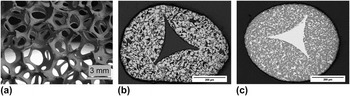
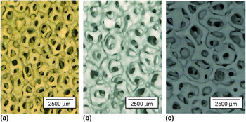
Ceramic foams made of silicate-bonded silicon carbide, alumina, and zirconia (ZrO2) are commonly used in the industry. Currently, molten metal filtration is the main field of application of ceramic foams.Reference Taylor6–Reference Aneziris, Dudczig, Emmel, Berek, Schmidt and Hubalkova11 Due to their open-celled structure, ceramic foams have attracted great interest in other fields of application. In the past few decades, a lot of researchers have been trying to create new materials with higher chemical purity and enhanced properties compared with the conventional quality of metal filters.Reference Scheffler and Colombo12,Reference Bucharsky, Schell, Oberacker and Hoffmann13 Two examples worth mentioning are LigaFill®-foams made of siliconized silicon carbide with nearly dense ceramic strutsReference Adler and Standke14,Reference Ortona, Gianella and Gaia15 and an extremely higher strength than conventional foam materials (Fig. 1) as well as pure sintered silicon carbide (SSiC) foams with one of the highest thermal stabilities among the suitable materials for burners.Reference Adler, Standke, Jahn and Marschallek16
(a) Typical foam structure, (b) hollow and microporous SSiC-foam strut, and (c) dense SiSiC-foam strut (LigaFill®).

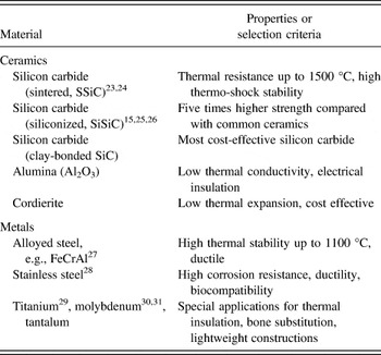
There are different approaches to manufacture materials and components made of open-celled metal foams including investment casting, chemical vapor deposition coating,Reference Paserin, Marcuson, Shu and Wilkinson17 galvanic deposition, and powder-based replicationReference Adler, Kümmel, Quadbeck, Standke, Stephani, Kieback and Stephani18 and their combinations. However, the practical application of these methods is limited on a few fields such as bone replacementReference Zardiackas, Parsell, Dillon, Mitchell, Nunnery and Poggie19,Reference Ronold, Lyngstadaas and Ellingsen20 and automotive retrofit catalyst carriers.Reference Jatkar21,Reference Koltsakis, Katsaounis, Markomanolakis, Samaras, Naumann, Saberi and Böhm22 Nevertheless, a large variety of materials ranging from nonferrous metals to different steel alloys can be manufactured as open-celled foams by the replication method (Table I).
Sintered replica foams and their main properties.

An important issue for the use of ceramic or metal foams is the characterization of their cellular structure as well as their resulting cell size after coating with functional layers. Their structure is commonly described as being a set of distorted pentagon-dodecahedrons or tetrakaidecahedrons or combinations of both.Reference Phelan, Weaire and Brakke32 This cell structure is determined by the reticulated polyurethane foams used. These are usually classified by their mean cell sizes measured in pores per inch (ppi) according to an American Society for Testing and Materials standard33 in a range of 8–90 ppi. This standard does not illustrate the foam structure sufficiently since there is a big difference between the cell (the former bubble diameter) and the cell windows. Neither these different cell sizes nor their distortions are registered by the measurement with the above-mentioned standard. For this reason, new characterization methods using computer tomography or special cell-counting techniques are under development. But at present, no commercially used methods exist. One alternative is a special optical method where only the surface of the foams is lighted.34 As a result, only the struts on the surface are pictured making it possible to reconstruct the foam cells. The equivalent circular diameter (ecd) of these reconstructed cells acts as a measurement value and provides more information about the material used and their prospective properties. The measurement technique works very fast compared with computer tomography. Moreover, it can both be used for controlling the quality of polyurethane foams as well as sintered structures.
Another important characteristic of foam structures, especially in the context of functional coatings, is the specific geometrical surface area S geo, which specifies the surface that is available for the coating material per volume. Until now, there has been a lack of suitable measurement methods for the experimental determination of this important parameter.
However, academic literature offers several model calculations on the estimation of the specific geometrical surface. The basis for more complex models was presented by Gibson and AshbyReference Gibson and Ashby35 who illustrated the foam cell as a specific regular network, such as a package of cubic cells, hexagonal prisms, rhombic dodecahedrons, or tetrakaidecahedrons. Based on this work, further models were developed, e.g., by Richardson et al.Reference Richardson, Peng and Remue36 and Buciuman and Kraushaar-Czarnetzki.Reference Buciuman and Kraushaar-Czarnetzki37 A similar approach was chosen by Grosse et al.Reference Grosse, Dietrich, Garrido, Habisreuther, Zarzalis, Martin, Kind and Kraushaar-Czarnetzki38 Her calculation model is based on the Weaire–Phelan structure and shows a good correlation to data determined by magnetic resonance tomography (MRT) of alumina and silicon carbide foams. According to this model, the specific geometrical surface area S geo depends on the diameter of the cell window d w, the diameter of the foam strut d s, and the open foam porosity ε0 [Eq. (1)].
 $$S_{{\rm{geo}}} = {{4.84\left( {1 - {\rm{\varepsilon }}_0 } \right)^{0.5} - 2.64\left( {1 - {\rm{\varepsilon }}_0 } \right)} \over {d_{\rm{F}} + d_{\rm{s}} }}\quad .$$
Another model that focuses on metallic foams was derived by Giani et al.Reference Giani, Groppi and Tronconi39 A paper by Inayat et al.Reference Inayat, Freund, Zeiser and Schwieger40 provides a good overview on the different models for simulation of foam structure known from the literature. The calculation of this model takes the shape of the foam struts that depend on the open foam porosity ε0 into consideration.
III. COATING OF FOAM STRUCTURES
A. State of the art
Currently, catalytic coating is the most frequently used method for the functionalization of open-celled foams. However, apart from research and development, there has not been any significant industrial application yet. Catalytic coating of open foams has been used in scientific research for catalysis processes that include oxidation of hydrogen,Reference Farrauto, Liu, Ruettinger, Ilinich, Shore and Giroux41,Reference Haruta, Souma and Sano42 oxidation of carbon monoxide (CO),Reference Chin, Sun, Roberts and Spivey43 combustion of hydrocarbons, e.g., methane,Reference Cerri, Saracco and Specchia44,Reference Jirátová, Morávková, Malecha and Koutský45 partial oxidation of methanol,Reference Pestryakov, Lunin, Devochkin, Petrov, Bogdanchikova and Petranovskii46 and in classical catalytic processes, such as water gas shift reaction and Fischer–Tropsch synthesis.Reference Wang, Vanderwiel, Tonkovich, Gao and Baker47,Reference Güttel, Kunz and Turek48 A paper by Reitzmann et al.Reference Reitzmann, Patcas and Kraushaar-Czarnetzki49 provides a good overview on previous publications on catalytic coatings of foams and also summarizes the extensive work of Twigg and Richardson.Reference Richardson and Twigg50–Reference Twigg and Richardson52
Although many papers about research activities done on open-celled foams as catalyst supports can be found, information on the coating technology itself is very limited. This problem is especially highlighted by the lack of description of materials and process technologies applied. Most described coating methods are slurry-based. In this method, cellular structures are dipped into slurry or a precursor solution of the catalytically active material,Reference Fino, Russo, Saracco and Specchia3–Reference Van Setten, Bremmer, Jelles, Makkee and Moulijn5,Reference Van Setten, van Gulijk, Makkee and Moulijn53 and the excessive slurry is removed by shaking or blowing with compressed air.Reference Twigg and Richardson51,Reference Richardson, Garrait and Hung54 The used slurries or precursor solutions often have a very low viscosity to prevent them from blocking the network-like structure of the foam. This approach leads to thin and irregular layers on the foam struts. After drying and calcination, the same coating method is repeated until the desired loading is reached.Reference Twigg and Richardson52,Reference Buciuman and Kraushaar-Czarnetzki55
In summary, the literature available shows that a homogeneous and entire coating of the three-dimensional network is a key task for the implementation of foams into a wide range of industrial applications. Compared with plane substrates, foams possess a high surface area-to-volume ratio, which leads to additional effects (e.g., capillarity) that must be taken into account using slurry-based coating methods. To meet the challenge of homogeneous coating, the rheology of slurries needs to be adjusted according to the coating technology. This concerns both the characteristics like wetting of the whole foam network and adhesion on the foam struts.Reference Reitzmann, Patcas and Kraushaar-Czarnetzki49 To improve adhesion, scientific papers mention different ideas for the pretreatment of foam surfaces, e.g., the oxidation of silicon carbide foams or etching in case of metallic foams.Reference Giani, Cristiani, Groppi and Tronconi4
B. New coating technology
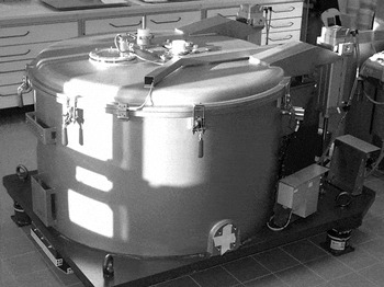
The coating technology described in this paper is a combination of dip coating and spin coating using a vertical centrifuge (diameter: 1100 mm, maximum rotational speed: 1000 1/min, spin efficiency “C” max: 615). During the first step (“dip coating”) where the foam is dipped into the coating slurry, special care must be taken to ensure that the network is completely saturated and wetted with slurry. This procedure depends on the foam size but it is usually completed after a short immersion time of about 10 s. After dipping, the ceramic foam is removed from slurry and drained to have a minimal loss of the same.
In the second step (“spin coating”), a vertical centrifuge is used to remove excessive slurry from the foam network (Fig. 2). A homogeneous layer of a defined thickness is formed depending on the chosen process parameters (particularly speed of rotation) and slurry properties [e.g., solid content (sc)]. The coating quality is considered perfect when the foam network is both completely coated and open-celled at the same time. Otherwise, the core of especially large foam components could be blocked and might cause undesirable effects in its practical application (e.g., a high pressure drop or inhomogeneous gas flow in chemical reactors).
Vertical centrifuge used for coating open-celled foams.

The size of the foams that can be coated by the above-described method is limited by the size of the centrifuge basket. Inserts with a dimension of 500 × 500 mm were used for this work. Consequently, it is possible to upscale this coating technology to large-sized foam structures, which can have various interesting industrial applications.
The coating technology enables the deposition of functional layers of a definite thickness of up to 100 µm. Therefore, it is necessary to develop coating slurries of an adapted flow behavior and comparably high sc—in contrast to conventional washcoat techniques which often use low-concentrated precursor solutions with Newtonian flow behavior. The slurry viscosity must be low enough to immerse the whole network during dipping or centrifugation. However, the slurry also needs to have a high enough viscosity to ensure a good adhesion on the foams struts and to form homogeneous functional layers of a certain thickness. To adjust this flow behavior, special binder systems and additives are used to meet these required processing characteristics.
C. Calculation model for the estimation of coating thickness
For the practical application of the coating technology, it might be beneficial to first identify the optimum process parameters (e.g., sc of the slurry or rotational speed of the centrifuge) to reach high-quality coatings of targeted layer thicknesses. Based on the technological parameters of the developed coating technology and the shear-thinning flow behavior of the slurries, a new calculation model for estimation of coating thickness on the foam struts was derived. This calculation model differs entirely from existing models of Landau and LevichReference Landau and Levich56 describing the flow of Newtonian liquids during the dip coating process or Emslie et al.Reference Emslie, Bonner and Peck57 describing the flow of Newtonian liquids during the spin-coating process.
Similar to the developed coating technology, the new calculation model includes both the process steps of dipping and centrifugation. During the first step, the layer thickness d dip that is formed by dipping can be calculated as a result of the weight force of the slurry layer [Eq. (2)]. The main influence parameters on this maximum attainable layer thickness are the yield point τ0 and the slurry density ρS.
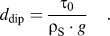 $$d_{{\rm{dip}}} = {{{\rm{\tau }}_0 } \over {{\rm{\rho }}_{\rm{S}} \cdot g}}\quad .$$
The layer thickness d dip is an important parameter for the determination of the layer thickness d spin, which is formed by centrifugation (spinning) as a result of the centrifugal force. For the estimation of the layer thickness d spin, a new process-related slurry parameter called, the “representative shear stress,” τrep is defined. The experimental determination of this parameter is discussed below. The layer thickness d spin also depends on the slurry density ρS and on the technological parameter radial acceleration a r [Eq. (3)].
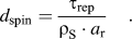 $$d_{{\rm{spin}}} = {{{\rm{\tau }}_{{\rm{rep}}} } \over {{\rm{\rho }}_{\rm{S}} \cdot a_{\rm{r}} }}\quad .$$
The radial acceleration a r can be regulated by the rotational speed N of the centrifuge and depends on the distance between the centrifuge insert and the center of the centrifuge R where the foam sample is located [Eq. (4)].
 $$a_{{\rm{r}}(R)} = {{v^2 } \over R} = 4{\rm{\pi }}^2 RN^2 {\rm{ \,\,with }}\,\,v = 2{\rm{\pi }}RN\quad .$$
This shows that to calculate the medium layer thickness  $\bar d_{{\rm{spin}}}$ of a foam sample with the thickness D, the distance between the centrifuge insert and the center of the centrifuge reduced by the half foam thickness D/2 must be taken into account [Eq. (5)].
 $$\bar d_{{\rm{spin}}} = {{{\rm{\tau }}_{{\rm{rep}}} } \over {{\rm{\rho }}_{\rm{S}} \cdot a_{\rm{r}} (R - D/2)}}\quad .$$
In this way, it is possible to calculate the layer thickness of the foam sample at every point. The gradient of layer thickness along the sample thickness  ${\textstyle{{\Delta d_{{\rm{spin}}} } \over D}}$ can be calculated using Eq. (6).
 $${{\Delta d_{{\rm{spin}}} } \over D} = {{d_{{\rm{spin}}(R - D)} - d_{{\rm{spin}}(R)} } \over D} = {{{\textstyle{{{\rm{\tau }}_{{\rm{rep}}} } \over {4{\rm{\pi }}^2 \cdot N^2 }}} \cdot \left( {{\textstyle{1 \over {R - D}}} - {\textstyle{1 \over R}}} \right)} \over D}\quad .$$
One general remark is that the results of Eqs. (2) and (3) are the thicknesses of the wet layers. To calculate the layer thickness after heat treatment, i.e., drying or sintering, both equations need to be multiplied by the appropriate value of the layer shrinkage.
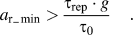
Giving the fact that d spin could never reach a higher value than d dip the “minimal radial acceleration” a r_min is defined first. This parameter is obtained from the ratio of τrep to τ0 [Eq. (7)] and must be set as the minimum value at the centrifuge to remove slurry from the saturated foam network and, thus, to ensure homogenous and particularly open-celled coatings.
 $$a_{{\rm{r}}\_\min } > {{{\rm{\tau }}_{{\rm{rep}}} \cdot g} \over {{\rm{\tau }}_0 }}\quad .$$
In conclusion, the calculation with the parameters τ0, τrep, a r, or N enable both the quantitative estimation of the layer thickness and the qualitative prediction of the coating result. For the application of the model, all the mentioned parameters need to be determined experimentally. In this case, the yield point τ0 and the representative shear stress are the results of rheological measurement using oscillating and rotating methods. The yield point is determined by means of the oscillatory tests “amplitude sweep,” as the value of shear stress τ that corresponds to the intersection of the curves for storage modulus G′ and loss modulus G″.Reference Mezger58
The representative shear stress τrep is identified by rheological rotation tests where the viscosity is measured as a function of the applied shear stress [Eq. (8)].
 $${\rm{\eta }} = f(\tau )\quad .$$
This function enables the determination of τrep as the point where the viscosity of the shear thinning slurry shows nearly no decrease anymore. Mathematically, τrep can be expressed as the value of shear stress where the slope of the curve approaches zero. In this work, τrep was determined when the slope m of the curve reached 0.1 Pa/mPa s:
 $$m = f'\left( {{\rm{\tau }}_{{\rm{rep}}} } \right) = 0.1{{{\rm{Pa}}} \over {{\rm{mPa\,\, s}}}}\quad .$$
Besides the evaluation of τ0 and τrep by rheological measurements, the slurry density was determined by the liter weight method. The radial acceleration a r as procedural variable can be adjusted by the rotational speed N of the centrifuge.
D. Example of proof: Comparison of experimental and calculated data
The correlations described above have been verified by a number of experiments. In this section, the validity of both the coating technology and the calculation model is presented by the example of one specific washcoat for catalytic applications.
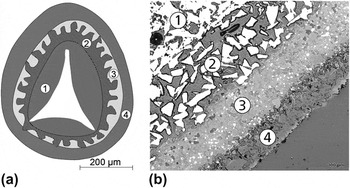
Due to foam supports having special advantages in the field of catalytic high temperature applications like highly exothermic oxidation reactions, a multilayer washcoat system with a thermal resistance of up to 1300 °C is used to illustrate the comparison of experimental and calculated data. As depicted in Fig. 3, the material system consists of a thermal shock resistant SSiC foam as support, a layer with rough SiC particles, a mullite intermediate layer, and a calcium aluminate (CA) washcoat.Reference Boettge, Adler and Standke59 The illustrated multilayer system exemplifies the different effects of the functional layers. The task of the first layer that consists of rough SiC particles is to improve the adhesion and homogeneous dispersion of the next layers on the SSiC foam struts. The mullite intermediate layer is applied in between the SiC foam and the CA washcoat. The function of the mullite intermediate layer is to prevent reactions between SiO2 (oxidized SiC) and CA at high operating temperatures and to guarantee the thermal stability of the material combinations of the “foam/washcoat.” The CA washcoat determines the application characteristics of the multilayer system. It mainly consists of calcium hexaaluminate (CA6) as the primary phase and provides a high specific surface area at temperatures of up to 1200 °C.
Square section of the multilayer system for catalytic applications: (a) schematic figure and (b) light microscopic image (1, hollow SiC ceramic strut; 2, layer with rough SiC particles; 3, mullite intermediate layer; and 4, CA washcoat layer).

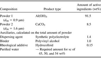
The applicability of the coating technology and the comparison between the experimental and calculated data are described by using the CA washcoat layer as an example. Systematic coating tests have been carried out on SSiC foam samples with a cubic dimension of 40 × 40 × 25 mm3. CA slurries with three different sc (45wt%, 50 wt%, 54 wt%) were developed and characterized to determine the required material parameters for the calculation of the layer thicknesses d dip and  $\bar d_{{\rm{spin}}}$ of the CA washcoat layers by using Eqs. (2) and (5). The composition of the CA slurries is shown in Table II. The coating layers consisting of the CA phase were formed in situ on the foam by calcination of the slurry layers at 1200 °C.
Slurry composition used for the formation of the CA washcoat layers.

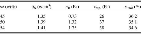
All the developed suspensions with three different sc were stable and they were not prone to sedimentation. They showed the desired shear thinning flow behavior and a yield point. Table III summarizes the results of slurry characterizations including the obtained drying and sinter shrinkage values (s total) at 1200 °C.
Material parameters of the developed CA slurries and CA layers (sc: solid content, ρS: slurry density, τ0: yield point, τrep: representative shear stress, s total: drying and sinter shrinkage of CA layers).
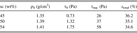
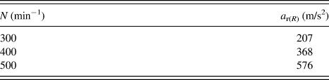
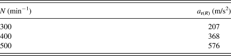
As expected, the values of slurry density ρS, yield point τ0, and representative shear stress τrep increase, whereas the drying and sinter shrinkage s total of CA layers decreases with a higher level of slurry sc. In addition to this variation of the material parameters, the radial acceleration has been varied in three steps by regulating the rotational speed, N, of the centrifuge shown in Fig. 2. These three different rotational speeds and the corresponding radial accelerations in the middle of the foam samples are presented in Table IV.
Rotational speeds and corresponding radial accelerations, a r(R − D/2) in the middle of the foam samples.
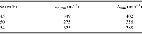
Before the experimental determination of the CA washcoat layer thickness, the calculation model was applied first using material and technical parameters shown in Tables III and IV. At first, the required minimal radial acceleration a r_min that should be assigned at the centrifuge to remove the slurry out of the saturated foam network was calculated by using Eq. (7). Table V shows the required values for a r_min and the corresponding minimal rotational speeds N min, which depend on the sc of the CA slurries.
Required minimal radial acceleration a r_min and minimal rotational speeds N min depending on the sc of the CA-slurries.
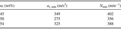
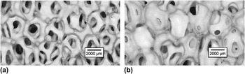
The calculated results of N min reveal that a rotational speed of 300 min−1 is insufficient to cause a decrease in the layer thickness compared with the dipping step of all three sc. This is confirmed by the experimental results as illustrated in Fig. 4 by stereomicroscopic images.
Stereomicroscopic images of a CA-coated foam network with different chosen parameters (a) sc: 54 wt%; N: 500 min−1 and (b) sc: 54 wt%; N: 300 min−1.

Figure 4(a) shows a good coating quality that was reached by the coating of SSiC foams (ppi20) with a CA slurry (sc: 54 wt%) at a rotational speed N of 500 min−1 that is higher than the calculated minimal rotational speed N min. The stereomicroscopic image shows a complete open-celled foam network and homogeneously coated foam struts. Whereas Fig. 4(b) illustrates that a rotational speed of 300 min−1 was insufficient to remove the slurry that drains from the foam struts and accumulates in the foam cells and thus blocking the cell structure. Thus, Fig. 4 demonstrates that a r_min is generally a good parameter for assessing the coating quality.
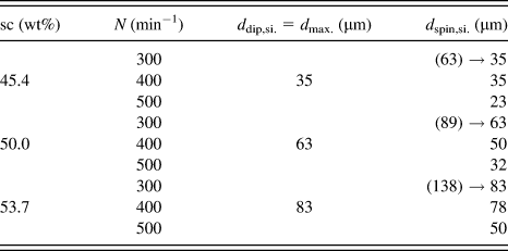
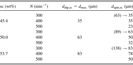
Table VI shows the calculated thicknesses for sintered CA layers d dip,si. and d spin,si. in relation to sc and rotational speed N, which were calculated with Eqs. (2) and (5) using material and technical parameters mentioned previously in Tables III and IV. Compared with the previous results, it becomes apparent that the theoretical layer thicknesses d spin,si. for 300 min−1 are higher than the layer thicknesses d dip,si. This implies the necessity to adjust the rotational speed of the centrifuge.
Calculated layer thickness for dip coating step d dip,si and spin coating step d spin,si. depending on the sc of the coating slurry and rotational speed (N) of the centrifuge.
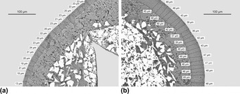
After calculation the layer thickness was measured on at least three samples per parameter variation according to German Institute for Standardization (DIN EN 1071-10) using scanning electron microscopic (SEM) and light microscopic images. Special care was taken to measure only foam struts with nearly perpendicular cut. Figure 5 shows two examples in measuring the layer thickness of two different CA layers.
Measurement of layer thickness on light microscopic images of perpendicular cut foam struts: (a) sc: 45 wt%; N: 400 m−1 and (b) sc: 50 wt%; N: 400 m−1.

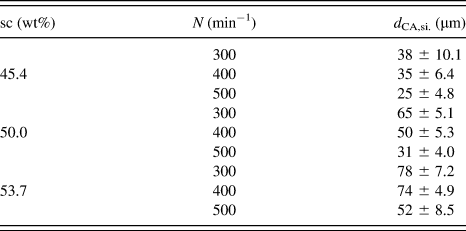
Table VII summarizes the mean values and standard deviations (±) of the measured thicknesses of sintered CA layers in dependence of the sc of the CA slurry and the rotational speed N of the centrifuge.
Measured layer thicknesses d CA,Si. depending on the sc and rotational speed N.
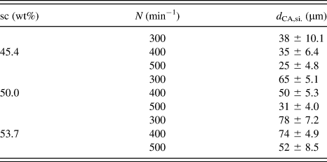
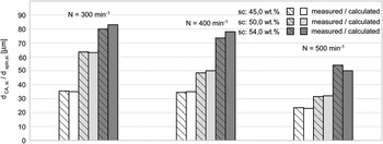
As shown in Fig. 6, the results show that the measured and calculated values match each other well.
Comparison of measured coating thicknesses d CA,si. and calculated values d spin,si..

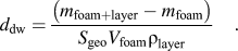
Another quick method for estimating the layer thickness is the differential weighing of the foam samples both before and after layer deposition. By using Eq. (10), the resulting coating mass m dw can be converted to a corresponding layer thickness d dw. The equation assumes the layer thickness to be homogenously distributed at the entire substrate (m foam+layer = mass of the coated substrate, m substrate = mass of the uncoated substrate, S geo = specific geometrical surface area of the foam, V foam = volume of the foam sample, and ρlayer = density of the coating).
 $$d_{{\rm{dw}}} = {{\left( {m_{{\rm{foam + layer}}} - m_{{\rm{foam}}} } \right)} \over {S_{{\rm{geo}}} V_{{\rm{foam}}} {\rm{\rho }}_{{\rm{layer}}} }}\quad .$$
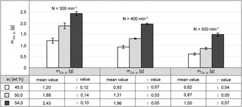
Figure 7 shows the measured masses of the sintered CA layers m CA,si. depending on the sc and the rotational speed, N. The masses refer to foam samples having a cubic dimension of 40 × 40 × 25 mm3 and a cell size of 20 ppi. As expected, the coating masses increase with decreasing rotational speed and increasing the sc. The amount of washcoat loading that can be achieved during coating of SSiC foams (20 ppi) by CA washcoat ranges from 15.5 to 60.8 g/L depending on the sc of the coating slurry and rotational speed, N, of the centrifuge.
Measured mass (m CA,si.) of sintered CA layers depending on the sc of the coating slurry and rotational speed N of the centrifuge.

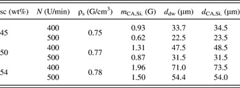
Based on the results as summarized in Fig. 7, the layer thickness was calculated according to Eq. (10) by using the sample volume, V foam, of 40,000 mm3 (40 × 40 × 25 mm3) and the specific geometrical surface area, S geo, of about 920 m2/m3, which was calculated by Eq. (1). The results in Table VIII show a good level of congruency between the calculated and the measured values and thus verifying successful prediction of coating thickness by a simple weighing method.
Comparison of calculated (d dw) and measured (d CA,Si.) layer thicknesses.

In summary, it is proved that the new coating technology can be described by the calculation model that offers very good approximate estimation of layer thicknesses. These layer thickness estimations enable one to control the parameters for the coating process before starting experimental procedures. Furthermore, they are particularly important in fields of application where a precise amount of coating material on foam supports is highly desired. Using the combined techniques of dip coating and centrifugation, it is possible to apply tailor-made amounts of coating material on foam and to predict whether the cell size of the foam structure will remain open-celled after coating or not.
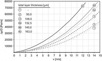
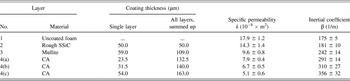
Pressure drop behavior of catalytic-coated foams is a very important characteristic for process engineering and hence plays a significant role in reactor design. For this reason, pressure drop measurements were carried out on SSiC foam samples with a geometry of 40 × 40 × 25 mm3 and a cell size of 20 ppi at a velocity range of up to 15 m/s. The pressure drop measurements were also performed after each single coating step of the multilayer system shown in Fig. 3 [uncoated foam (1) + rough particle layer (2) + mullite layer (3) + three various CA layer thicknesses (4a–c)] to demonstrate the influence of the layer thickness on the pressure drop. The permeability measurements of the uncoated and coated foams are represented in Fig. 8.
Measured normalized pressure drop Δp/D for an SSiC foam (20 ppi) as a function of superficial air velocity v for different total layer thicknesses [uncoated foam (1) + rough particle layer (2) + mullite layer (3) + three different CA layer thicknesses (Figs. 4a, 4b, and 4c)].

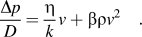
The pressure drop curves show a parabolic increase depending on the superficial air velocity (Fig. 8), which is a typical trend of open-celled foams. The increase in layer thickness that in turn decreases the cell diameter leads to an increase of pressure drop in an exponential manner. This relation can be described by the Hagen–Poiseuille law which states that the pressure drop inversely raises to the fourth power of the cell diameter.Reference Philipse and Schram60 The results obtained were analyzed according to the following Darcy–Forchheimer equation:
 $${{\Delta p} \over D} = {{\rm{\eta }} \over k}v + {\rm{\beta \rho }}v^2 \quad .$$
where D is the thickness of the foam sample (25 mm), v is the superficial air velocity, η is the dynamic viscosity, ρ is the density of the flowing gas, k is the specific permeability, and β is the inertial coefficient.
Table IX shows the measured values of specific permeabilities, k, and inertial coefficients, β.
Mean value and standard deviation of specific permeabilities k and inertial coefficients β of uncoated and step-by-step coated SSiC foams.

As expected, the specific permeability value decreases, whereas the inertial coefficient increases with increasing layer thickness values. Consequently, both the layer thickness and the homogeneity greatly influence the pressure drop behavior. This example demonstrates the importance of a well-defined coating on the resulting application characteristics.
IV. EXAMPLES AND APPLICATIONS
A. Rough surface layers
The purpose of a layer consisting of coarse particles is to improve the adhesion of secondary coatings or other materials such as composites. To develop these rough surfaces, a slurry of coarse particles has to be prepared and deposited on the foam struts by the previously described coating technique. This principle can be adapted to a large number of various ceramic and metallic foams.Reference Standke, Adler and Boettge61
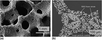
Figure 9 illustrates SSiC foam coated with rough SiC particles that could be used as a preform for MMCs (see Sec. IV. D).
Images of an SSiC foam with a rough surface layer: (a) SEM picture of foam topography and (b) cross-section of coated foam struts.

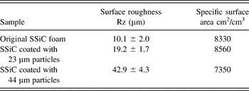
As shown in Table X, the roughness of the resulting layer can be adjusted by the particle size of the applied powder. It can be seen that surface roughness increases with coarser particles, but specific surface area either remains or drops with highly coarse particles.
Roughness and specific surface area of SSiC foams coated with different particle sizes in comparison to a typical original SSiC foam surface; ecd 2.3 mm.

B. Catalytic coatings
An overview on scientific research with coated foams in catalysis was presented in Sec. III. A. In this section, the multilayered washcoat system, presented in Sec. III. D, is described in detail. As mentioned in the previous section, the CA washcoat provides a high specific surface area even at high temperatures of up to 1200 °C. Thus, the material combination is suitable for highly exothermic oxidation reactions where local overheating could occur. To use the developed material system in catalytic reactors, the CA washcoat was additionally impregnated with catalytically active component by using an ethanolic solution of manganese(II) nitrate tetrahydrate, which was then oxidized to form manganese oxide. Catalyst-coated foams made up of such a material combination were successfully tested in catalytic reactors for catalytic combustion of lean gases (<25% methane) obtained from landfills and coal mines.Reference Boettge, Adler, Stephani, Hipke, Scheffler and Adler62 They were also applied for the oxidation of CO in the afterburner of a solid oxide fuel cell system.Reference Jahn, Heddrich, Weder, Reichelt and Lange63
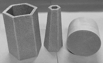
Another possible practical application of catalytic-coated foams is the after treatment of exhaust in automobilesReference Pestryakov, Yurchenko and Feofilov64 or for the removal of soot from diesel exhaust gas.Reference Van Setten, Bremmer, Jelles, Makkee and Moulijn65,Reference Van Setten, van Gulijk, Makkee and Moulijn66 In this field of application, honeycomb structures are mainly used due to their favorable pressure drop behavior and their resilience to vibrations.Reference Carty and Lednor67 Because of their ductility, metallic foams are also suitable materials for exhaust after treatment in automobiles. A comparison between catalytic-coated iron–chromium–aluminium (FeCrAl) alloy metallic foams and cordierite honeycombs has resulted in a promising catalytic activity. For these tests, metallic foams were coated with a mixed oxide washcoat containing ceria, ZrO2, γ-Al2O3 and small amounts of precious metals (Fig. 10).
FeCrAl foams (left and center) and cordierite honeycomb coated with a mixed oxide washcoat.

Another example within the context of catalysis is the catalytic combustion of waste gases from industrial processes. For this application, ceramic foams made of silicon carbide were coated with thin layers of a special perovskite-typed catalyst. Due to the open-celled structure and the low-density value of the foams, those material combinations can be heated by conventional external heating as well as by microwave radiation. Combining different ceramic substrates and coatings makes it possible to vary the heating behavior by microwaves. The combination of SSiC foam with perovskite catalyst coating shows excellent results in a pilot unit to clean air from high levels of vinyl acetate and methane at comparably low temperatures. The results are encouraging as this could save process energy and precious metal catalysts in industrial waste gas combustion.Reference Boettge, Adler, Standke, Krech, Krippendorf and Scholz68
C. Adsorbent coatings
Another interesting field of application is the adsorption process utilized for the purification of exhaust gases, removal of hydrogen sulfide, or solvent recovery. In general, the industry, using fixed-bed reactors filled with activated carbon pellets or zeolite pellets. The main disadvantage of these fixed bed reactor structures is their high pressure drop. Another disadvantage is the occurrence of hot spots due to local overheating especially during the usage of activated carbon pellets. However, both drawbacks can be avoided by using coated foam structures instead. Figure 11 illustrates the possibility of homogeneous adsorbent coatings on cordierite foams without blocking the open-celled structure.
Stereomicroscopic images of uncoated and adsorbent-coated cordierite foams for environmental engineering applications (a) uncoated cordierite foam, (b) zeolite coated, and (c) activated carbon coated.

D. Preforms for MMCs
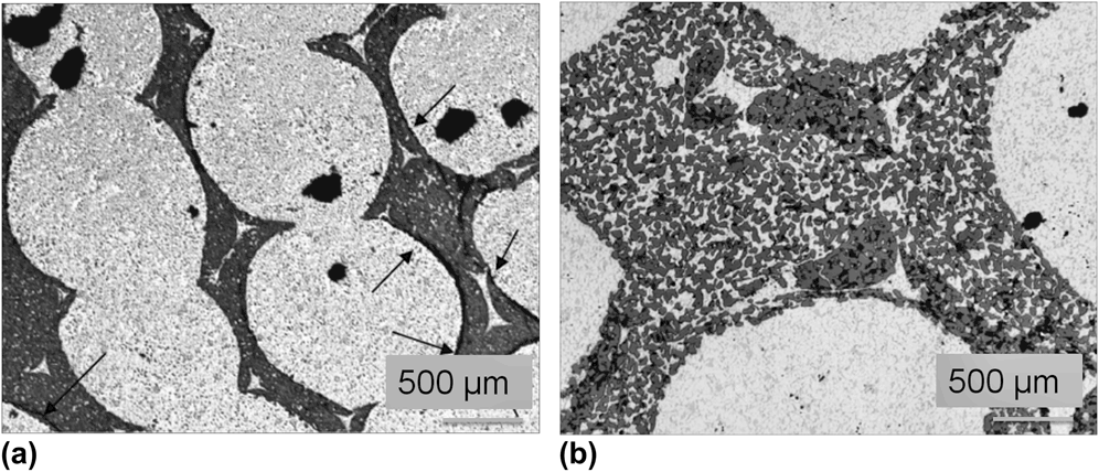
Over the last decades, ceramic foams as reinforcing preforms in MMCs have proven themselves since they offer cost-effective production methods in various attractive geometries.Reference Zeuner, Stojanov, Busse and Sahm69 Their main field of application is in wear protection and in increasing stiffness of light metals.Reference Schreiner, Regener, Ambos and Ziesemann70 The foams are filled with metal using gravity and high-pressure casting techniques. One major problem is the dissimilar thermal expansion coefficient of metal and ceramics. This leads to delamination effects at the interface [Fig. 12(a)]. As a result, lower strength and Young’s moduli were measured compared with the original metal properties. To overcome this mismatch and to form an interlocking mechanism between the metal and the ceramic, coating of coarse particles on the ceramic foam was applied. Preforms made of ceramic foams coated with rough surfaces were successfully applied using high-pressure die casting method. The metal infiltrated nearly all pores in the ceramic preform [Fig. 12(b)]. As a result, no delamination areas were observed and the measurements showed a high-specific stiffness of up to E/ρ = 42 GPa cm3/g compared with the conventional Al or Mg alloys (E/ρ = 25–27 GPa cm3/g).Reference Standke, Müller, Neubrand, Weise and Göpfert71
(a) Micrographs of Al-infiltrated SSiC foams; bright: Al alloy, dark: SSiC. (a) Uncoated SSiC foam showing delaminations at the metal–ceramic interface (see arrows) and (b) SSiC foam coated with coarse particles after metal infiltration. No delamination is visible here.

The tests were mainly conducted using foams with an ecd of 1000 µm. But it is also applicable for finer foams with ecds of 500 µm. One additional advantage of the functionalized coating is the higher ceramic content of the preform. Typical foam preforms with 10–15 wt% ceramic content show only limited improvements of wear protection and stiffness. With the described technique, however, ceramic contents of up to 30 wt% could be achieved resulting in better mechanical properties.
E. Corrosion protection
There are several reasons for the application of corrosion protection layers to ceramic or metal foams. One often discussed subject is the degradation of foam materials in burner atmospheres, particularly of nonoxide ceramics or metals by oxidation.Reference Acchar, Ramalho, Souza, Torquato, Rodrigues and Innocentini72–Reference Presas, Pastor, Lorca, Martín, Segurado and González74 Oxidation protecting layers could enhance the lifetime of such components since they prevent the decrease of mechanical properties under such harsh conditions. Furthermore, protection layers are also useful against aggressive melts and chemicals. And third, intermediate layers are necessary to prevent reactions between coating and substrate, e.g., a mullite layer between CA coating and SiC substrate, as described in Sec. III. D. Following are the requirements to oxidation protection layers: their principal oxidation resistance, no reactions between layer and substrate at high temperatures, an excellent bonding as well as nearly similar coefficients of thermal expansion. For the variety of materials, the foam strut microstructure is mainly porous and hence show inner oxidation. Therefore, it is necessary to create coatings with dense microstructures compared with the struts. The following paragraph describes oxidation protection barrier coatings at SiC foams for burner applications.
One concept consists of applying a mixture of alumina, yttria, and silicon carbide powders to generate a liquid yttrium–aluminium-garnet-phase during sintering to form a dense layer on the strut surface. The powders are coated by a multistage process (up to three steps) to seal cracks which occur during the sintering. The level of the oxidation protection was evaluated by measuring the mass change and electrical resistance after annealing at 1200 °C. It was discovered that, with increasing layer thickness, the mass change decreases and the electrical resistance is stabilized at about 1 MΩ at temperatures between 700 °C and 1000 °C.Reference Martin, Standke and Adler75
Another material concept for antioxidation coatings on open-celled SiC foams is the application of thin and strongly bonded mullite layers formed by slurries that consist of silicone resin and nano-sized alumina.Reference Bernardo, Parcianello, Colombo, Adler and Boettge76
V. CONCLUSIONS
In this paper, a two-stepped slurry-based technique of dip coating and centrifugation using a vertical centrifuge was developed for coating open-celled foams. The result indicates that homogeneous functional layers with a definite thickness of up to 100 µm could be deposited using shear-thinning slurries with high sc. The coating technology was applied and demonstrated by a complex multilayer system consisting of a thermal shock resistant SSiC foam as support, a layer with rough SiC particles, a mullite intermediate layer, and a CA washcoat.
A calculation model was derived to predict the coating thickness on foam struts based on the technological parameters of the developed coating technology and the shear-thinning flow behavior of the slurries. The model was successfully proved using the example of a CA washcoat layer. New process-relevant parameters have been identified to be used in the calculation model: first, the representative shear stress t rep that significantly affects the formation of the layer thickness during centrifugation. And second, the minimal radial acceleration a r_min that must be set as a minimum at the centrifuge to remove slurry from the saturated foam network ensuring homogenous and open-celled coatings. Consequently, the calculation model allows both quantitative estimation of the layer thickness and qualitative assessment of the resulting coating quality. Thus, the coating process can be precisely regulated.
In conclusion, a targeted application of the described coating technology in combination with the calculation model enables the production of tailor-made material combinations of “foam + functional layer.” These offer a large number of practical applications in the field of process engineering and environmental technologies. This fact is illustrated by different material combinations such as layers made of coarse particles, zeolites, activated carbon, γ-Al2O3, perovskites, mullite, and yttria–alumina–garnet on SiC–, Al2O3–, or cordierite foams. These functionalized foams can be applied for a large number of applications, e.g., as adsorbents and catalysts at environmental engineering, as preforms for MMCs and for special purposes, which requires corrosion and oxidation resistance.
ACKNOWLEDGMENT
Parts of the presented work were financially supported by German Federal Ministry of Education and Research (BMBF) and BMWI (Grant Nos. 01LS05016 and AiF161ZBR/2).
NOMENCLATURE
a r
radial acceleration
a r_min
minimal radial acceleration
d CA,si.
measured layer thicknesses of CA-washcoat
d dip
layer thickness that is formed by dipping
d spin
layer thickness that is formed by centrifugation (spinning)
 $\bar d_{{\rm{spin}}}$
medium layer thickness that is formed by centrifugation (spinning)
d s
diameter of the foam strut
d w
diameter of the cell window
D
foam thickness
E/ρ
specific stiffness
G′
storage modulus
G″
loss modulus
k
specific permeability
N
rotational speed of the centrifuge
Δp
pressure drop
sc
solid content
S geo
specific geometrical surface area
s total
drying and sinter shrinkage
V
superficial air velocity
Greek letters
β
inertial coefficient
ε0
open foam porosity
η
dynamic viscosity
ρ
gas density
ρS
slurry density
τ0
yield point
τrep
representative shear stress