1. Introduction
As the tokamak concept has developed over the last 50 years and advanced towards the ITER design, numerous challenges have occurred and many have been solved. One of the remaining tasks is control or mitigation of runaway electrons (RE) in ITER after the disruption. Estimations from codes predict RE with several tens of MeV to carry up to 70 % of pre-disruptive plasma current (Hender et al. Reference Hender, Wesley, Bialek, Bondeson, Boozer, Buttery, Garofalo, Goodman, Granetz, Gribov, Gruber, Gryaznevich, Giruzzi, Günter, Hayashi, Helander, Hegna, Howell, Humphreys, Huysmans, Hyatt, Isayama, Jardin, Kawano, Kellman, Kessel, Koslowski, La Haye, Lazzaro, Liu, Lukash, Manickam, Medvedev, Mertens, Mirnov, Nakamura, Navratil, Okabayashi, Ozeki, Paccagnella, Pautasso, Porcelli, Pustovitov, Riccardo, Sato, Sauter, Schaffer, Shimada, Sonato, Strait, Sugihara, Takechi, Turnbull, Westerhof, Whyte, Yoshino and Zohm2007, p. S178). As deposition of a runaway electron beam can be highly localised, it could severely damage plasma-facing components and blanket modules of ITER.
The electron is said to ‘run away’ when the collisional drag force acting on it becomes smaller than the accelerating force coming from the toroidal electric field
 $E_{tor}$
. There are three main mechanisms for runaway generation: (i) the Dreicer (primary) mechanism (Dreicer Reference Dreicer1959, Reference Dreicer1960); (ii) the hot-tail mechanism (Smith & Verwichte Reference Smith and Verwichte2008); (iii) the avalanche (secondary) mechanism (Rosenbluth & Putvinski Reference Rosenbluth and Putvinski1997). However, there is a theoretical limit for the electrical field, the so-called critical field,
 $E_{crit}$
, under which RE cannot be produced by these mechanisms (Connor & Hastie Reference Connor and Hastie1975). The toroidal electric field
 $E_{tor}$
in ITER during the stable discharge will be under the
 $E_{crit}$
threshold, making the controlled ITER plasma void of RE. On the other hand, if disruption occurs, first the thermal energy is lost in a relatively short time (called thermal quench, TQ), causing electron temperature
 $T_{e}$
to drop, and thus plasma electric resistivity
 ${\it\eta}$
would increase. TQ is followed by loss of magnetic energy (called current quench, CQ), which typically lasts longer than TQ. Thus
 $E_{tor}$
, being proportional to
 ${\it\eta}\,j$
, will rise dramatically during the CQ, as
 ${\it\eta}$
increases faster than
 $j$
decreases. This increase of the field will first induce runaway seeds that will then be multiplied enormously by the avalanche effect. In the ITER disruption scenarios, the avalanche multiplication factor could be as large as
 $10^{22}$
(Hender et al.
Reference Hender, Wesley, Bialek, Bondeson, Boozer, Buttery, Garofalo, Goodman, Granetz, Gribov, Gruber, Gryaznevich, Giruzzi, Günter, Hayashi, Helander, Hegna, Howell, Humphreys, Huysmans, Hyatt, Isayama, Jardin, Kawano, Kellman, Kessel, Koslowski, La Haye, Lazzaro, Liu, Lukash, Manickam, Medvedev, Mertens, Mirnov, Nakamura, Navratil, Okabayashi, Ozeki, Paccagnella, Pautasso, Porcelli, Pustovitov, Riccardo, Sato, Sauter, Schaffer, Shimada, Sonato, Strait, Sugihara, Takechi, Turnbull, Westerhof, Whyte, Yoshino and Zohm2007, table 5), forming an electron beam that could threaten ITER’s first wall structure. Following the above outline, ITER should be equipped with a proper suppression and/or mitigation technique dedicated to RE control. Thus, achieving a post-disruptive RE beam is one of the first significant steps for COMPASS towards ITER-relevant runaway suppression/mitigation studies.
The COMPASS tokamak (Pánek et al.
Reference Pánek, Adámek, Aftanas, Bílková, Böhm, Cahyna, Cavalier, Dejarnac, Dimitrova, Grover, Háček, Havlíček, Havránek, Horáček, Hron, Imríšek, Janky, Komm, Kovařík, Krbec, Kripner, Markovič, Mitošinková, Mlynář, Naydenkova, Peterka, Seidl, Stöckel, Štefániková, Tomeš, Urban, Vondráček, Varavin, Varju, Weinzettl and Zajac2015) is a experimental fusion device with major radius
 $R_{0}=0.56~\text{m}$
and minor radius
 $a=0.2~\text{m}$
. The toroidal magnetic field
 $B_{tor}$
is in the range 0.9–2.1 T, and the plasma current
 $I_{p}$
can reach up to 400 kA. Electron densities are flexible and are typically of order of magnitude
 $10^{19}{-}10^{20}~\text{m}^{-3}$
. Plasma shaping varies from circular and elliptical to single-null D-shaped ITER-like plasmas. The typical pulse length is 0.4 s, although the low-current circular discharge with RE can last almost 1 s. Furthermore, flexibility of various plasma parameters (e.g. shaping, densities, plasma current, etc.) combined with a significant, but still safe, runaway population make COMPASS suitable for runaway model validation and scaling towards ITER.
In contrast to large tokamaks (e.g. JET, ITER), where most of the RE are usually produced during the disruption (Martin, Chatelier & Doloc Reference Martin, Chatelier and Doloc1995; Yoshino, Tokuda & Kawano Reference Yoshino, Tokuda and Kawano1999; Gill et al.
Reference Gill, Alper, Edwards, Ingesson, Johnson and Ward2000), in small and medium size tokamaks RE are typically created either during the current ramp-up or the flat-top phase (Esposito et al.
Reference Esposito, Martín-Solís, Poli, Mier, Sánchez and Panaccione2003; Papřok, Krlín & Stöckel Reference Papřok, Krlín and Stöckel2013), when
 $n_{e}$
is low and/or
 $E_{tor}$
is high enough. Moreover, the present COMPASS maximum value for
 $B_{tor}$
is 1.25 T, while various works have noted that it is not possible to obtain the post-disruptive RE spontaneously if
 $B_{tor}$
is under
 ${\approx}2~\text{T}$
(Martin et al.
Reference Martin, Chatelier and Doloc1995; Yoshino et al.
Reference Yoshino, Tokuda and Kawano1999; Gill et al.
Reference Gill, Alper, de Baar, Hender, Johnson and Riccardo2002). The
 $B_{tor}$
-limit is the most probable reason for the lack of post-disruptive runaway observations in COMPASS. Therefore the size of COMPASS and its maximum
 $B_{tor}$
might disqualify this facility from ITER-relevant runaway suppression/mitigation research. Nevertheless, experiments where
 $B_{tor}$
was under 2 T and with post-disruptive RE have been achieved with a high-
 $Z$
massive gas injection (MGI) (Yoshino et al.
Reference Yoshino, Tokuda and Kawano1999; Gill et al.
Reference Gill, Alper, de Baar, Hender, Johnson and Riccardo2002; Hollmann et al.
Reference Hollmann, Austin, Boedo, Brooks, Commaux, Eidietis, Humphreys, Izzo, James, Jernigan, Loarte, Martín-Solís, Moyer, Muñoz-Burgos, Parks, Rudakov, Strait, Tsui, Van Zeeland, Wesley and Yu2013) or high-
 $Z$
pellet injection (Yoshino et al.
Reference Yoshino, Tokuda and Kawano1999; Hollmann et al.
Reference Hollmann, Austin, Boedo, Brooks, Commaux, Eidietis, Humphreys, Izzo, James, Jernigan, Loarte, Martín-Solís, Moyer, Muñoz-Burgos, Parks, Rudakov, Strait, Tsui, Van Zeeland, Wesley and Yu2013). Moreover, a detailed study of the
 $B_{tor}$
-limit as a function of the amount of Ar injected was performed recently in JET (Plyusnin et al.
Reference Plyusnin, Reux, Kiptily, Shevelev, Mlynar, Lehnen, de Vries, Khilkevitch, Huber, Sergienko, Pereira, Alves, Alper, Kruezi, Jachmich, Fernandes, Brix, Riccardo, Giacomelli, Sozzi, Gerasimov, Manzanares, de La Luna, Boboc and Matthews2014), where post-disruptive RE were observed even for
 $B_{tor}=1.0~\text{T}$
. Therefore, Ar injection was used to trigger the first post-disruptive RE in COMPASS.
The paper is organised as follows. In § 2, the experimental setup used for the experiments and demonstration of runaway plateau observation is presented. In § 3, general runaway parameters are reported, followed by details of the injection and disruption. The section finishes with the discharge analyses of the parameters important for plateau occurrence. In § 4, the results presented in § 3 are discussed. Finally, in § 5 conclusions and future perspectives are addressed.
2. Experiment
2.1. Experimental setup
In all discharges described in this paper the plasmas were circular, limited by the carbon high field side (HFS) wall, with an additional carbon low field side (LFS) limiter for inner wall vessel protection (see figure 1). The typical magnetic field
 $B_{tor}$
was 1.15 T, and plasma currents
 $I_{p}$
at the moment of the gas injection varied from
 $40$
to 140 kA. The electron density
 $n_{e}$
was relatively low (
 $0.8{-}2.2\times 10^{19}~\text{m}^{-3}$
), to maximise runaway generation. The schematics of the experimental setup used in the experiments presented here are shown in figure 1. In this article, measurements of runaway losses will be presented from a photoneutron (PN) detector located near the north wall and a NaI(Tl) scintillator for hard x-ray (HXR) detection located in the south-east part of the tokamak hall. Both detectors are approximately 5 m from the vessel. Photoneutrons with energy of a few MeV are observed with the ZnS(Ag) neutron detector embedded in a plastic matrix. As well as neutrons, the PN detector is suspected to be sensitive to strong HXR flux, although the detector is shielded by 10 cm of Pb. HXR are measured with an unshielded NaI(Tl) scintillation detector, where the signal is amplified by a photomultiplier tube and the energy range is approximately from 100 keV to a few MeV. Furthermore, the low-energy photon radiation measurements will be presented by an
 $H_{{\it\alpha}}$
detector and bolometry. The
 $H_{{\it\alpha}}$
detector is located radially in the eastern part of the tokamak vessel. AXUV photodiodes, located in the north-west part of the tokamak vessel, with a photon energy response from 7 eV to 10 keV, are used for bolometric measurements.
Principal diagnostics used for the RE plateau studies.

A MGI of argon was achieved using a solenoid valve, located on the east side of the tokamak. The solenoid gas valve is connected to the vessel through two stainless steel tubes: the first is 20 cm long and has an inner diameter of 4 mm, while the second is 40 cm long and has an inner diameter of 6 mm. This non-negligible tube length implies a delay between the time of valve opening and the time at which the argon puff starts to interact with the plasma, i.e. roughly the time at which the gas enters the vacuum vessel. The delay is estimated to be approximately 1 ms, taking into account a mean velocity of approximately
 $400~\text{m}~\text{s}^{-1}$
for argon gas in vacuum at 300 K.
The Ar flow rate
 $\text{d}N/\text{d}t$
through the injection system was evaluated experimentally as a function of the back pressure
 $p_{back}$
and with linear dependence as follows:
 $$\begin{eqnarray}\frac{\text{d}N}{\text{d}t}=(9.5511\,p_{back}-1.0083)\times 10^{20},\end{eqnarray}$$
where
 $p_{back}$
is in bars and
 $\text{d}N/\text{d}t$
is in
 $\text{particles}~\text{s}^{-1}$
. The pressure
 $p_{back}$
used for the plateau discharges were
 $2.4$
and 1.2 bar, corresponding to particle flow rates of
 $(2\pm 0.4)\times 10^{21}$
and
 $(1\pm 0.2)\times 10^{21}~\text{particles}~\text{s}^{-1}$
, respectively. The valve is roughly estimated to be open for 2 ms; better knowledge of gas valve performance will soon be available via installation of a fast-opening and more reliable valve.
Since there is a non-negligible pipe length between the valve and the tokamak vessel, the puff duration is actually larger than the opening time of the valve, as we shall show in the following. For the two aforementioned back pressures, 2.4 bar and 1.2 bar, the manufacturer gives a flux through the solenoid valve at standard conditions of
 $100$
and
 $50~\text{Pa}~\text{m}^{3}~\text{s}^{-1}$
, corresponding to flow rates of
 $2.4\times 10^{22}$
and
 $1.2\times 10^{22}~\text{particles}~\text{s}^{-1}$
at 300 K, respectively. Therefore, assuming a constant flow rate of the solenoid gas valve with the increase of pressure in the stainless steel pipe and neglecting the flow rate through the injection system in the tokamak, one can calculate the number of particles that fill the pipe and that will be puffed in the tokamak later on. Remembering that the valve stays open for about 2 ms, one can find that there will be about
 $5\times 10^{19}$
and
 $2.5\times 10^{19}$
particles for 2.4 bar and 1.2 bar, respectively. Notice that these numbers are much smaller than the total number of particles that can be stored in the pipes at 2.4 bar and 1.2 bar (
 $8\times 10^{22}$
and
 $4\times 10^{22}$
respectively), justifying the assumption of constant flow rate through the solenoid valve. Now, knowing the flow rate through the injection system and the number of particles in the pipes, one can give an estimation of what the Ar puff duration in the tokamak vessel is: 25 ms for 2.4 bar and 12.5 ms for 1.2 bar. The runaway plateau created in this manner lasted from
 $2.5$
to 10 ms; hence one can see that the amount of Ar needed to trigger the disruption is smaller than the total amount injected.
2.2. Plateau observation
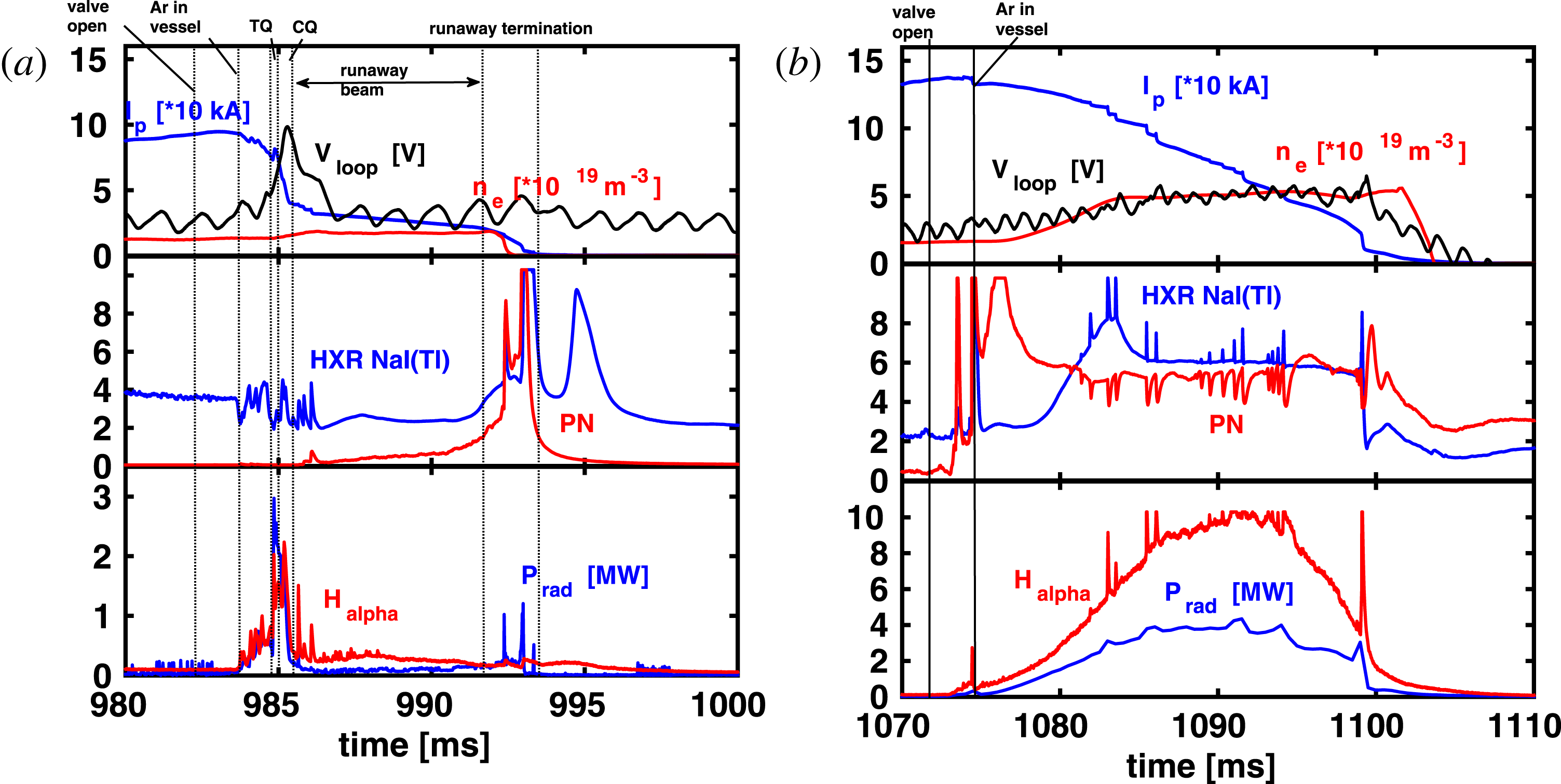
An example of a typical COMPASS discharge with MGI-generated runaway plateau is shown in figure 2(a), together with slow
 $I_{p}$
decay for comparison in figure 2(b). Figure 2(a) shows plateau discharge number 8585, when the Ar puff starts to cool down the plasma,
 $I_{p}$
starts to drop and plasma radiation increases. After approximately 2 ms (this delay will be justified in the next section), TQ occurs and almost all plasma energy is radiated. At the same time the HXR measurement shows relatively low peaks in a half-saturated state and the PN signal is rather low, meaning that high-energy RE created during the discharge initial phase are still confined. Then, during the CQ,
 $E_{tor}$
is increased and boosts runaway production, creating and amplifying the runaway beam. After the CQ the runaway beam carries a non-zero current called
 $I_{RE}$
, lasting for a few milliseconds, as can be seen from the top graph in figure 2(a). Finally, the RE beam terminates with the loss seen in HXR and PN signals, while there are almost no
 $H_{{\it\alpha}}$
radiation and radiated power
 $P_{rad}$
from plasma proving the existence of a runaway plateau. On the other hand, COMPASS discharge number 8616 (see figure 2
b) displays an example of slow radiative decay with MGI on COMPASS resembling to
 $I_{p}$
ramp-down, for which no TQ or CQ (a typical sign of fast disruption) are observed. In this discharge plasma radiates on a long time scale (
 ${\approx}20~\text{ms}$
). Although the HXR and PN signals show the presence of released RE, we shall not consider this as the runaway plateau, because the
 $I_{p}$
current is mainly driven by the thermalised plasma and not by the runaway beam, as one can see from strong
 $H_{{\it\alpha}}$
emission. Notice that the difference in
 $H_{{\it\alpha}}$
and
 $P_{rad}$
measurements makes the distinction between the runaway plateau and the slow radiative
 $I_{p}$
decay. The former has a relatively low radiation level after the disruption, indicating that there is only cold plasma beside the runaway population.
Time evolution of COMPASS discharge 8585 as an example of a runaway beam (a) and discharge 8616 as an example of slow
 $I_{p}$
decay (b), both initiated by MGI. Top plots: plasma current
 $I_{p}$
, electron density
 $n_{e}$
(an increase in
 $n_{e}$
corresponds to low-temperature Ar plasma, as RE ionise Ar atoms) and loop voltage
 $V_{loop}$
(oscillations in
 $V_{loop}$
originate from the design of the central solenoid circuit). Middle plots: HXR (there are indications – in particular in
 $I_{p}$
– that the second peak is real and reflects longer confinement of high energy RE) and PN signals, showing RE losses on the wall. Bottom plots:
 $H_{{\it\alpha}}$
and
 $P_{rad}$
measurements, showing radiation losses from plasma (note that the
 $y$
-axes are different for the two discharges).

As a supplement to the previous description of the RE plateau, the observation of an RE beam with a visible light camera is displayed in figure 3 for discharge 8585. The creation and localisation of the beam are easily seen.
Visual observation of the RE beam with a visible light camera for discharge 8585: (a) before Ar reaches vessel, (b) formation of the RE beam on HFS, (c) RE beam, and (d) RE beam drifts towards LFS.

3. Results
Out of 137 discharges performed during the COMPASS RE campaign, an Ar puff was used in 39 discharges of which only 5 discharges ended in spontaneous disruption, i.e. not triggered by the Ar puff. Out of the remaining 34 discharges, 14 had the RE plateau after the Ar puff, while 9 resulted in slow radiative
 $I_{p}$
decay, similar to a ramp-down. The remaining 11 discharges ended in a typical COMPASS disruption, i.e. without any RE.
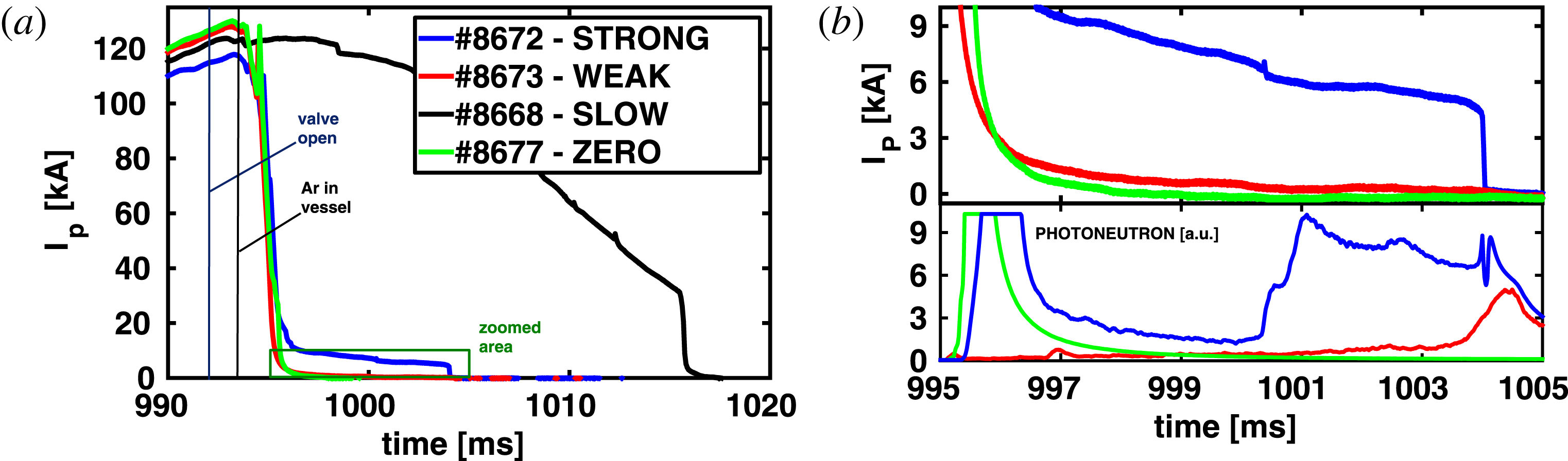
Based on these observations, all discharges with the Ar puff can be classified as follows.
-
(i) Strong (RE plateau):
 $I_{RE}>5~\text{kA}$
.
-
(ii) Weak (RE plateau):
$I_{RE}<5~\text{kA}$
. -
(iii) Slow (radiative current decay): the plasma current slowly decreases in a similar way to a ramp-down phase.
-
(iv) Zero (RE plateau): a ‘typical’ disruption for COMPASS, with no RE remaining or generated after the disruption.


Classification examples: (a) discharge 8672 for a strong plateau, 8673 for a weak plateau, 8668 for slow plasma current decay and 8677 as an example of disruption without RE surviving or produced. (b) Close-up of (a) for better observation of the difference between the weak and zero plateaus, as well as the photoneutron signal for comparison of the strong, weak and zero cases.

An example of each class is shown in figure 4, where figure 4(b) is a close-up of figure 4(a) to emphasise the difference between weak and zero plateau measurements. Although these two cases might seem identical at first sight, the PN signal confirms the release of the RE after disruption in the weak case (ii) and their loss during disruption in the zero case (iv). This classification is very important, as it will be used from now on throughout the paper. We shall now present the main results of the RE COMPASS campaign.
First, assuming that RE are created at the very beginning of the discharge, the typical maximum runaway energy for the analysed discharges is estimated to be 10–15 MeV, taking into account the electron acceleration due to the electric field with the synchrotron radiation losses only, as suggested in Martín-Solís, Sánchez & Esposito (Reference Martín-Solís, Sánchez and Esposito2010) and Yu et al. (Reference Yu, Hollmann, Commaux, Eidietis, Humphreys, James, Jernigan and Moyer2013).
Second, since the RE before or during the disruption are more likely to be produced in the hottest part of the plasma (Gill et al.
Reference Gill, Alper, de Baar, Hender, Johnson and Riccardo2002), the remaining and newly produced post-disruptive RE may have a more peaked radial current profile than the pre-disruption
 $I_{p}$
profile. The peaking represents localisation of the plasma current
 $I_{p}$
around the magnetic axis and can be expressed through the internal inductance
 $l_{i}$
, which is calculated by the EFIT reconstruction (Havlíček & Hronová Reference Havlíček and Hronová2010) at COMPASS. One of the promising/potential methods to evaluate
 $l_{i}$
is to calculate the Shafranov
 ${\it\Lambda}$
by adding
 ${\it\beta}_{p}$
and
 $l_{i}/2$
from EFIT and then evaluate the value of the effective
 ${\it\beta}_{p}$
for the relativistic particles, as explained in Kuznetsov et al. (Reference Kuznetsov, Galvão, Bellintani, Ferreira, Fonseca, Nascimento, Ruchko, Saettone, Tsypin and Usuriaga2004):
 ${\it\beta}_{p}=\sqrt{{\it\gamma}^{2}-1}I_{A}/I_{RE}$
, where
 ${\it\gamma}$
is the relativistic Lorentz factor,
 $I_{A}$
is the Alfvén current (
 ${\sim}17~\text{kA}$
) and
 $I_{RE}$
is the current carried by the RE. As one can see, an estimate of the average runaway electron energy is required (for calculation of
 ${\it\gamma}$
). It is not possible to acquire the measurement of the average RE energy with the present diagnostics in COMPASS, so the value of 1 MeV will be taken as the typical theoretical estimation for low-
 $n_{e}$
COMPASS discharges (Kocmanová Reference Kocmanová2012). After performing this calculation, it was observed that the
 $l_{i}$
value increases by a factor of 1.5–3.5, which is comparable to the measurements for JET (Loarte et al.
Reference Loarte, Riccardo, Martín-Solís, Paley, Huber and Lehnen2011). In addition to the rise in
 $l_{i}$
, the normalised plasma pressure
 ${\it\beta}_{n}$
rises above
 $1.5$
for the same discharges and thus confirms that the overestimated
 ${\it\beta}_{n}$
as seen by EFIT (Vlainić et al.
Reference Vlainić, Mlynář, Weinzettl, Papřok, Imrísek, Ficker, Vondráček and Havlíček2015) is caused by the presence of RE.
The inward motion (towards the HFS wall, negative
 $R-R_{0}$
values in figure 5) of the post-disruptive plasma, followed by its return towards the vessel centre, is in agreement with the Tokamak Fusion Test Reactor (TFTR) (Fredrickson et al.
Reference Fredrickson, Bell, Taylor and Medley2015) and Tore Supra (Saint-Laurent et al.
Reference Saint-Laurent, Reux, Bucalossi, Loarte, Bremond, Gil and Moreau2009) observations. However, the TFTR and Tore Supra feedback systems were able to stabilise the runaway beam, while at present in COMPASS the beam continues to shift outwards until its termination, as shown in figure 5. Note that the outward shift is also visible in figure 3. The vertical plasma position for the majority of cases is rather stable (an example being given in figure 5); downward shifts were noticed in only a few discharges.
Time evolution of plasma vertical
 $Z$
and horizontal
 $R-R_{0}$
positions for COMPASS discharge 8585, associated with the plasma current
 $I_{p}$
barycentre. Positive values of
 $R-R_{0}$
mean that the plasma
 $I_{p}$
barycentre is closer to the LFS, and positive values of
 $Z$
mean that the plasma
 $I_{p}$
barycentre is closer to the top of the vessel.

3.1. Disruption generated by argon
As already mentioned, a solenoid valve was used to inject Ar gas into the plasma. Even though two different pressures were used (
 $2.4$
and 1.2 bar), no particular differences in runaway beam parameters were identified. The reason might be that the pressure was varied by only a factor of 2.
In devices larger than COMPASS, high-
 $Z$
gas injection is used to trigger fast CQ in order to improve runaway generation (Reux et al.
Reference Reux, Plyusnin, Alper, Alves, Bazylev, Belonohy, Brezinsek, Decker, Devaux, de Vries, Fil, Gerasimov, Lupelli, Jachmich, Khilkevitch, Kiptily, Koslowski, Kruezi, Lehnen, Manzanares, Mlynář, Nardon, Nilsson, Riccardo, Saint-Laurent, Shevelev and Sozzi2014). The plasma current quench rate
 $I_{{\it\gamma}}$
,
 $$\begin{eqnarray}I_{{\it\gamma}}=\frac{1}{I_{p}}\frac{\text{d}I_{p}}{\text{d}t},\end{eqnarray}$$
is the quantifying parameter for the CQ speed. The calculation of
 $I_{{\it\gamma}}$
values for disruptions with and without the Ar puff was performed. No particular differences were observed between the discharges, as the majority of the
 $I_{{\it\gamma}}$
values are in the range
 $500{-}1800~\text{s}^{-1}$
in both cases. The values suggest that the whole pre-disruptive
 $I_{p}$
is lost in 0.55–2 ms. Notice that all the values are slightly larger than the electromagnetic field penetration time of the COMPASS vacuum vessel (
 ${\sim}0.5~\text{ms}$
), which is labelled as ‘slow current termination’ in Yoshino et al. (Reference Yoshino, Tokuda and Kawano1999).
3.2. Parametrisation of runaway plateau
The ohmic heating (OH) central solenoid current
 $I_{OH}$
– called MFPS in Havlíček & Hronová (Reference Havlíček and Hronová2008) – will be used to indicate on the appearance time of the runaway plateau. For the RE discharges analysed in the article,
 $I_{OH}$
is negative during the current ramp-up phase, followed by
 $I_{OH}$
at zero value for a few milliseconds during the transition towards the current flat-top phase. For the rest of the discharge, i.e. current flat-top and ramp-down, it becomes positive and controlled by the feedback system (Janky et al.
Reference Janky, Havlíček, Batista, Kudlacek, Seidl, Neto, Pipek, Hron, Mikulin, Duarte, Carvalho, Stockel and Panek2014). In figure 6,
 $I_{OH}$
2 ms before TQ is plotted versus
 $I_{p}$
, also taken 2 ms before the TQ and denoted by
 $I_{disr}$
. The reason why exactly 2 ms are taken will be seen later in this section, but it can be explained as the time before Ar starts to cool down the plasma, displayed in figure 4(a). Also, later in the article, the measured parameters denoted by the suffix
 $disr$
(e.g.
 $E_{disr}$
and
 $n_{disr}$
) are taken at the same time.
Figure 6 shows that only one weak plateau out of 14 plateau discharges appeared during the ramp-down phase rather than the ramp-up phase. Hence, RE plateaus are more likely to be produced during the current ramp-up phase than during the flat-top phase. The ramp-down case requires further investigation in future experiments, as only one such discharge was observed.
 $I_{OH}$
as a function of the plasma current before the gas puff
 $I_{disr}$
. Negative values of
 $I_{OH}$
correspond to the current ramp-up phase, while positive values represent the current flat-top and ramp-down phases.

Yoshino et al. (Reference Yoshino, Tokuda and Kawano1999) did the first detailed parametrisation of disruptions with runaway occurrence in the JT-60U tokamak. According to his article, the study of
 $I_{{\it\gamma}}$
versus
 $q_{eff}$
is important for plateau occurrence, where the effective edge safety factor
 $q_{eff}$
for a circular plasma is defined as
 $$\begin{eqnarray}q_{eff}=\frac{5a^{2}B_{tor}}{RI_{p}}\left[1+\left(\frac{a}{R}\right)^{2}\left(1+\frac{({\it\beta}_{p}+l_{i}/2)^{2}}{2}\right)\right].\end{eqnarray}$$
The internal inductance
 $l_{i}$
and the poloidal beta
 ${\it\beta}_{p}$
are taken from the EFIT reconstruction at the closest moment from the disruption.
 $I_{{\it\gamma}}$
is already defined in (3.1). Figure 7 shows
 $I_{{\it\gamma}}$
versus
 $q_{eff}$
for the case of COMPASS. For all plateaus except the slow ones,
 $I_{{\it\gamma}}$
is between
 $500$
and
 $1800~\text{s}^{-1}$
and
 $q_{eff}$
is between
 $2.5$
and
 $8$
. It is interesting to observe how the majority of the zero disruptions are under
 $q_{eff}=3.5$
. Obviously, slow disruptions have significantly slower current decay than the rest of the discharges: their
 $I_{{\it\gamma}}$
values are under
 $100~\text{s}^{-1}$
.
Plasma current quench rate
 $I_{{\it\gamma}}$
as a function of
 $q_{eff}$
. The vertical red line corresponds to
 $q_{eff}=3.5$
and the horizontal blue line corresponds to
 $I_{{\it\gamma}}=500~\text{s}^{-1}$
.

According to the theory, the production of RE is more intense for lower densities. Thus,
 $E_{disr}$
normalised to
 $E_{crit}$
and
 $I_{disr}$
are plotted as a function of the line-averaged density
 $n_{disr}$
measured by the interferometer in figure 8. Approximately, the critical value of electron density for obtaining the runaway plateau seems to be
 $1.3\times 10^{19}~\text{m}^{-3}$
, but this is an indicative value only, due to sparse statistics. The ratio
 $E_{disr}/E_{crit}$
represents the relative strength of
 $V_{loop}$
. The critical value of the
 $E_{disr}/E_{crit}$
ratio in figure 8(a) is around
 $300$
for the analysed discharges. Figure 8(b) shows that the strong plateaus are created for a lower
 $I_{disr}$
value than weak plateaus, taking the same
 $n_{disr}$
value. In addition, no strong plateau is observed above
 $I_{disr}=120~\text{kA}$
, while half of the weak ones have
 $I_{disr}$
above 120 kA.
Normalised electric field
 $E_{disr}/E_{crit}$
(a) and plasma current just before the MGI puff
 $I_{disr}$
(b), as a function of the electron density
 $n_{disr}$
. The vertical blue line matches
 $n_{disr}=1.3\times 10^{19}~\text{m}^{-3}$
. The horizontal red line in (a) corresponds to
 $E_{disr}/E_{crit}=300$
, while the black line in (b) is for
 $I_{disr}=120~\text{kA}$
. The oblique green line in (b) represents the limit between the strong and weak cases.

Another parameter of interest is the current carried by the RE beam
 $I_{RE}$
. The dependence of
 $I_{RE}$
on the
 $I_{disr}$
is shown in figure 9(a), where only the ramp-up Ar MGI discharges are presented. The discharges in figure 9 are grouped by the time of the Ar puff. A typical weak plateau
 $I_{RE}$
is between 0.5 and 3.5 kA, while
 $I_{RE}$
for strong plateaus decreases with
 $I_{disr}$
and the time of the puff. Furthermore, for the Ar injections performed at 985 ms and 995 ms the upper limit of the
 $I_{disr}$
is indicated, namely 100 kA and 120 kA respectively. For values lower than these
 $I_{disr}$
values a strong plateau seems to be produced, while for higher values either a weak plateau or no plateau occurred. In contrast, for the Ar injection at 975 ms the lower limit of
 $I_{disr}$
is observed for about 70 kA, under which no plateau was detected. In any case, more statistics are required. The dependence of
 $I_{RE}$
on the maximum electric field
 $E_{CQ}$
during the current quench (figure 9
b) has similar behaviour to that shown in figure 9(a), as one might expect from the correlation between
 $I_{disr}$
and
 $E_{CQ}$
through the plasma inductance.
Runaway beam current
 $I_{RE}$
as a function of the pre-disruptive current
 $I_{disr}$
(a) and the maximum loop voltage during the current quench
 $E_{CQ}$
(b). The colours are kept the same as in previous figures, while different symbols correspond to different times of the Ar injection: 975 ms (squares), 985 ms (triangles), 995 ms (diamonds). Symbols stand for a mean value of the
 $I_{RE}$
, and error bars stand for maximum and minimum values of the
 $I_{RE}$
. The vertical lines in (a) match 70 kA (black), 100 kA (blue) and 120 kA (red).

4. Discussion
Even though the number of discharges devoted to runaway plateau studies was limited on COMPASS in the dedicated RE campaign, it was still possible to do comparative analyses. The results presented in the previous section are discussed in the following order:
-
∙ outline of general characteristics on RE,
-
∙ report on observed differences between discharges with and without a runaway plateau,
-
∙ discussion of issues on obtaining an RE plateau with an Ar puff,
-
∙ comments on achieving a strong plateau.
Loarte et al. (Reference Loarte, Riccardo, Martín-Solís, Paley, Huber and Lehnen2011) reported an increase of
 $l_{i}$
by factor of 2 to 3 for the RE plateau, which is similar to the values observed in COMPASS (1.5–3.5). These estimated values of
 $l_{i}$
have to be treated with care, as the correction of EFIT
 $l_{i}$
for relativistic particles requires knowledge of the average energy of RE, which is not possible to measure with the present diagnostic setup in COMPASS. Similarly to Tore Supra (Saint-Laurent et al.
Reference Saint-Laurent, Reux, Bucalossi, Loarte, Bremond, Gil and Moreau2009), JET (Loarte et al.
Reference Loarte, Riccardo, Martín-Solís, Paley, Huber and Lehnen2011) and TFTR (Fredrickson et al.
Reference Fredrickson, Bell, Taylor and Medley2015), the inward motion of the RE beam is observed at the beginning of the plateau phase in COMPASS.
Almost all (13 out of 14) generated RE plateaus were achieved for an Ar puff in the ramp-up current phase, as for Tore Supra (Saint-Laurent et al.
Reference Saint-Laurent, Bucalossi, Reux, Bremond, Douai, Gil and Moreau2011). Regarding disruptions themselves, the CQ speed is one order of magnitude larger than for the case of JT-60U (Yoshino et al.
Reference Yoshino, Tokuda and Kawano1999), where
 $I_{{\it\gamma}}>100{-}200~\text{s}^{-1}$
was reported as the plateau formation condition. In conclusion, COMPASS has sufficiently fast disruption for plateau formation (see figure 7), but other factors – e.g.
 $B_{tor}$
,
 $V_{loop}$
, avalanching (Rosenbluth & Putvinski Reference Rosenbluth and Putvinski1997) – are not fulfilled, thus explaining why the Ar MGI is necessary for COMPASS to obtain the runaway plateau.
Next,
 $q_{eff}$
and its relation to
 $I_{{\it\gamma}}$
is one more important plasma characteristic for plateau creation. In the case of JT-60U (Yoshino et al.
Reference Yoshino, Tokuda and Kawano1999), as well as the
 $I_{{\it\gamma}}$
condition,
 $q_{eff}$
has to be over
 $2.5$
. From figure 7 it is obvious that disruptions analysed here are deep in the reported parameter region. However, there is an indication of how the plateau condition for
 $I_{{\it\gamma}}$
and
 $q_{eff}$
in COMPASS could be different from those observed in JT-60U. In any case, this has yet to be investigated by enhancing the statistics.
As observed from figure 8(a), the limiting
 $n_{disr}$
for a plateau to appear is around
 $1.3\times 10^{19}~\text{m}^{-3}$
, which corresponds to
 $E_{crit}=0.0113~\text{V}~\text{m}^{-1}$
. The Dreicer mechanism is the most probable source of the post-disruptive production of RE at COMPASS, because avalanching is expected to be important for the tokamaks with
 $I_{P}\gtrsim 1~\text{MA}$
(Rosenbluth & Putvinski Reference Rosenbluth and Putvinski1997). However, from figure 8(a) it is apparent how strong plateaus are obtained for low
 $E_{disr}/E_{crit}$
values compared to weak plateaus. This observation, at first sight counter-intuitive, could be explained by the appearance of the avalanching effect, as avalanching is the dominant runaway generation mechanism for lower
 $E_{disr}/E_{crit}$
assuming that the electron temperature profile remains unchanged (see Nilsson et al.
Reference Nilsson, Decker, Peysson, Granetz, Saint-Laurent and Vlainić2015, figure 10). In any case, this possibility has yet to be investigated. The Dreicer field
 $E_{D}$
is currently difficult to determine as the Ar injections were often too early, so that no Thomson scattering data have yet been collected. For the cases plotted in figure 8(b), it seems that lower densities are necessary in order to achieve a plateau for
 $I_{disr}$
above 120 kA, making
 $I_{disr}$
an important parameter for plateau production.
In the COMPASS case, it seems that inverse dependence between
 $I_{RE}$
and
 $I_{disr}$
could be seen for strong plateaus (figure 9
a). The same dependence from figure 9(b) looks almost identical to that from figure 9(a), as one would expect. This observation comes from the fact that the amplitude of induced
 $E_{tor}$
during the CQ is directly proportional to the
 $I_{p}$
before the disruption, for the given
 $I_{{\it\gamma}}$
. The lower and upper boundary signs of plasma current for strong plateaus from figure 9(b) are not unique: these boundaries have been observed in JET by Gill et al. (Reference Gill, Alper, de Baar, Hender, Johnson and Riccardo2002). In this article, the lower limit is assigned to low
 $E_{tor}$
, while the upper limit is possibly connected to magnetic fluctuations. For COMPASS more discharges would be required to improve the statistics and find the two limits.
5. Conclusion and future work
Before this dedicated campaign, a runaway plateau had never been observed in COMPASS. As a matter of fact, there was scepticism concerning the possibility of plateau occurrence for any plasma condition, due to the size of the COMPASS tokamak, low
 $B_{tor}$
and the low plasma currents leading to relatively low electric field
 $E_{tor}$
during the disruption. Nevertheless, this paper reports a clear demonstration of obtaining a runaway plateau by MGI. The RE plateau currents varied between 0.5 and 40 kA, with a duration from
 $2.5$
to 10 ms.
Argon injection disrupted discharges in COMPASS have been investigated in order to clarify the necessary conditions for runaway plateau production. It was found that the easiest way to produce the RE plateau was to inject Ar during the ramp-up of the plasma current. Furthermore, the typical COMPASS disruptions without RE can satisfy various parameters important to runaway plateau creation (e.g.
 $n_{e}$
,
 $V_{loop}$
,
 $I_{{\it\gamma}}$
,
 $q_{eff}$
) without Ar injection, and thus high-
 $Z$
MGI is probably required only for activating thermal quench to enhance runaway population. Unusually, for the discharges considered in the paper, it seems that the plateau generation also depends on the plasma current during the Ar puff injection. Even though the CQ after MGI-induced disruption lasts a very short time, it is possible that the avalanche mechanism is present in COMPASS during runaway plateau formation.
More experiments need to be done in order to draw final conclusions on the definite conditions for runaway plateau generation in the COMPASS tokamak. From the present knowledge we can conclude that some observations correspond to reports from larger tokamaks, although the amplitude is sometimes different. Indeed, this difference in magnitudes could be important for scaling towards ITER.
The experiment presented here confirms that COMPASS is a tokamak suitable for various ITER-relevant runaway studies, such as:
-
(a) studies of runaway plateau termination – energy balances and timescales (Loarte et al. Reference Loarte, Riccardo, Martín-Solís, Paley, Huber and Lehnen2011; Martín-Solís et al. Reference Martín-Solís, Loarte, Hollmann, Esposito and Riccardo2014),
-
(b) improvements to runaway beam mitigation,
-
(c) testing the runaway control system,
-
(d) benchmarking of the runaway models.
Nonetheless, the scenario for inducing the runaway plateau is necessary before further ITER-relevant studies are performed. At present, the LUKE code (Decker & Peysson Reference Decker and Peysson2004) is being used in collaboration with CEA for a better understanding of the physics behind the measurements. In addition, new diagnostic systems are under consideration as an important condition for better understanding of the RE behaviour (e.g. towards improved evaluation of
 $l_{i}$
, neutron detection, direct HXR detection and synchrotron spectrum measurement).
Acknowledgements
The ‘Joint Doctoral Programme in Nuclear Fusion Science and Engineering’ is acknowledged by the first author for supporting these studies. The next to thank is the project MSMT LM2011021, which supports the operation of COMPASS. The authors would also like to acknowledge the work of the WP14-MST2-9 research project team. The first author would like to thank François Saint-Laurent for advising and sharing his experience with us, J. Varju for installing the injection system and J. Havlíček and M. Komm for fruitful discussions. The Faculty of Nuclear Sciences and Physical Engineering (Czech Technical University) is also appreciated for lending us the HXR detectors. This work was carried out within the framework of the EUROfusion Consortium and received funding from Euratom research and training programme 2014–2018 under grant agreement 633053. The views and opinions expressed herein do not necessarily reflect those of the European Commission.