Introduction
The development of advanced materials with desired properties is one of the main goals of materials research. Of a special interest are high-temperature and superhard materials for various applications, as well as alloys with improved wear, corrosion and mechanical resistance. The energetic electron and ion beams offer the possibility for modifying the properties of the near-surface layers of materials without seriously affecting their bulk (Proskurovsky et al., Reference Proskurovsky, Rotshtein, Ozur, Ivanov and Markov2000). Among these pulsed beam techniques, high-intensity pulsed ion beams (HIPIB) offer some essential advantages over electron or laser pulse treatment (Bystritskii and Didenko, Reference Bystritskii and Didenko1989; Renk et al., Reference Renk, Provencio, Prasad, Shlapakovski, Petrov, Yatsui, Jiang and Suematsu2004).
The modification of materials with high thermal conductivity (metals and alloys) require HIPIB with the energy density above 2–3 J/cm2 at a pulse duration of no more than 100–150 ns. High-energy density on the target can be achieved by focusing of the ion beam and eliminating its scattering during transportation to the target (Reiser, Reference Reiser2008). Ion diodes conventionally use geometric focusing that is obtained by making the anode and cathode of semi-cylindrical or hemispherical shape (Humphries, Reference Humphries1990). Several authors analyzed propagation and geometric focusing of pulsed ion beams. It was shown that magnetically insulated diodes exhibit a smaller ion beam divergence (arctangent of the ratio of the beam radius at half-height to the distance from the diode), typically amounting to 1–4°, in contrast to reflex diodes and pinch diodes (Olson, Reference Olson1982; Zieher, Reference Zieher1984a, Reference Zieher1984b; Yatsui et al., Reference Yatsui, Sai, Masugata, Ito and Matsui1985; Bystritskii et al., Reference Bystritskii, Glushko, Kharlov and Sinebryukhov1991).
Additional focusing of the ion beam can be obtained with the help of solenoidal or quadrupole magnetic lenses (Humphries, Reference Humphries1999). Unlike an electron beam, a large magnetic induction is required to focus the ions. For C+ ions with the energy of 200 keV in the convergent magnetic field (magnetic induction 1 T) of the solenoidal magnetic lens, the divergence is only 1.3° on the 1 cm path. It was shown that for focusing of ions with a large mass (m/Z>66) solenoids with a magnetic field >15 T should be used (Masunov and Samoshin, Reference Masunov and Samoshin2010).
A necessary condition for HIPIB efficient transport and focusing is neutralization of the ions space charge by low-energy electrons. In addition to eliminating the Coulomb repulsion of ions, low-energy electrons provide the possibility of additional ion focusing in the electric field. Focusing of a neutralized ion beam in a longitudinal magnetic field after passing through a grounded metal grid was considered in Humphries (Reference Humphries1990). The change in the trajectory of the electrons causes the formation of a transverse electric field and focusing of ions. At the current density of C+ ions of 1 A/cm2, the kinetic energy of 2 MeV, and the magnetic induction of 0.048 T, this method provides a 0.5° deviation of the ions.
However, at the accelerating voltage of 200–300 kV and the ion current density of 100–200 A/cm2 the magnetic field penetrates into the plasma of a neutralized ion beam in a depth of 5–6 mm at the beam diameter of 40–45 mm (Pushkarev and Isakova, Reference Pushkarev and Isakova2016). Therefore, magnetic focusing is only possible for low current ion beams. Space-charge lenses and plasma lenses (Humphries, Reference Humphries1990; Brown, Reference Brown Ian2006; Sharkov et al., Reference Sharkov, Hoffmann, Golubev and Yongtao2016) also allow one to focus the neutralized ion beam, but they greatly complicate the design of the HIPIB generator.
In Gabоviсh et al. (Reference Gabоviсh, Goncharov, Pritskii and Protsenkо1975) to limit the ion beam scatter, it was proposed to use the transverse electric field, formed by electrons space charge in the magnetic field. The electrons, formed at secondary electron emission from the target, which is under a negative potential, formed a reversed potential in the beam. The radius of the ion beam propagating in the transverse electric field varies periodically from the initial value to a certain minimum value.
Despite numerous studies into high-intensity ion beam focusing process and a detailed analysis of the causes of its scattering, now there are no experimental data on the effect of negative own space charge on its additional focusing in the drift region. According to the results of HIPIB space-charge neutralization measurements in self-magnetically insulated ion diodes, the concentration of neutralizing electrons exceeds the ions concentration by a factor of 1.3–1.5 (Zhu et al., Reference Zhu, Ding, Zhang, Isakova, Bondarenko, Pushkarev and Lei2017). It will cause Coulomb attraction of ions and additional HIPIB focusing. The aim of the study is to investigate and optimize ion beam focusing by own space charge.
Experimental setup
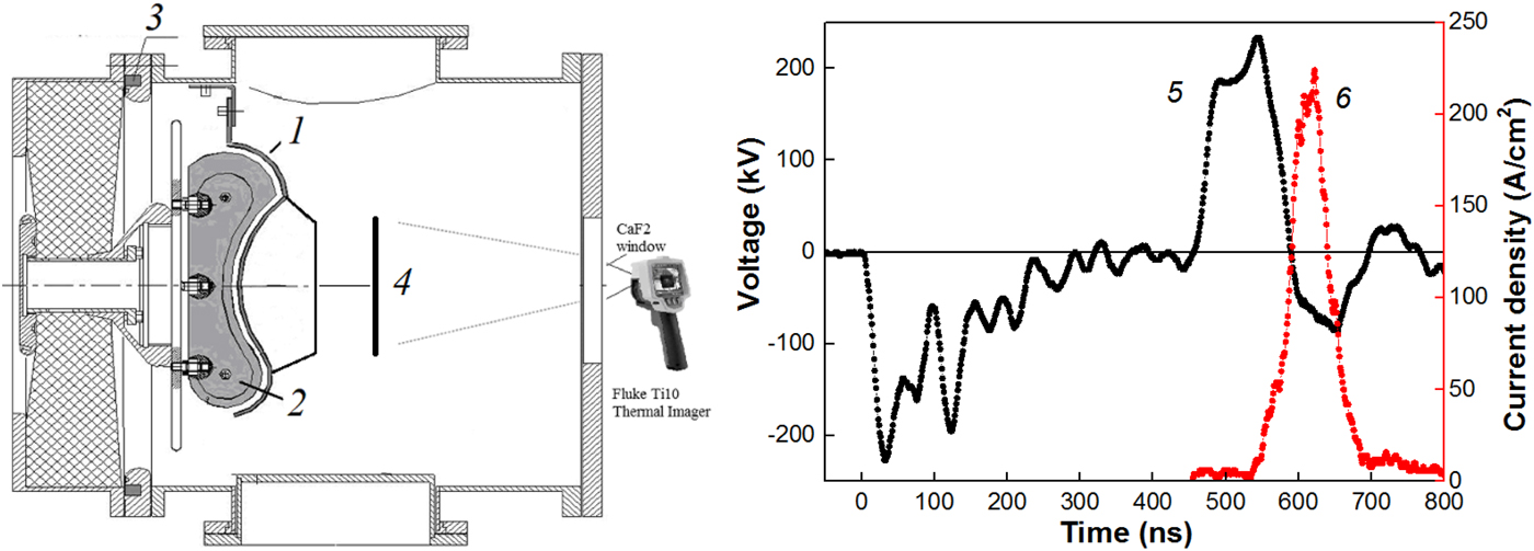
The experiments were conducted using the TEMP-6 pulsed accelerator (Zhu et al., Reference Zhu, Lei and Ma2002), which consists of a Marx generator, a double forming line (DFL) and a vacuum ion diode with self-magnetic insulation of electrons. The anode was made from graphite having a semi-cylindrical focusing curvature of 14 cm. The accelerator configured in bipolar pulse operation mode forms two pulses of opposite polarity: the first pulse is of negative polarity (plasma formation) followed by a second pulse of positive polarity (120 ns, 200–250 kV). The waveforms are shown in Fig. 1.
Schematic representation of the diode unit (1 – cathode, 2 – anode, 3 – Rogowski coil, 4 – target), waveforms of the accelerating voltage (5) and ion current density (6).
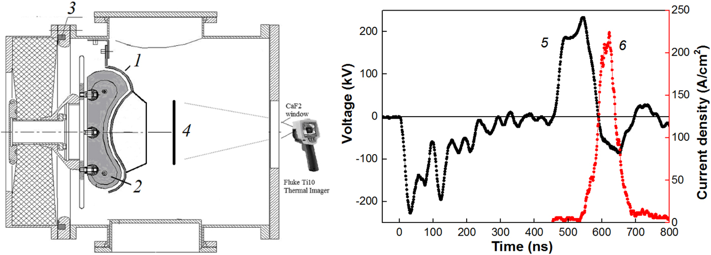
The voltage at the DFL output was measured with a voltage divider that was installed in the transition chamber between the DFL and diode unit. The current at the DFL output was measured using a Rogowski coil. Electric signals from the sensors were recorded with a Tektronix DPO 2024B oscilloscope (200 MHz, 5·109 readings/s).
For analysis of the ion beam parameters, we used the infrared (IR) imaging diagnostics of the beam energy density (spatial resolution of 1–2 mm) (Davis et al., Reference Davis, Bartsch, Olson, Rej and Waganaar1997; Isakova and Pushkarev, Reference Isakova and Pushkarev2018) and the time-of-flight diagnostics of the beam compositions (time resolution 1 ns) (Stephens, Reference Stephens1946; Isakova et al., Reference Isakova, Prima and Pushkarev2018). A Fluke Ti400 IR camera in the video mode, step 0.1 s, registered HIPIB IR images on the target. The delay between the HIPIB generation and the IR images registration was 0.1 s. A stainless steel target (125 mm × 150 mm and thickness of 0.1 mm) was placed 14 cm downstream from the cathode, in the diode focus.
Measurement of the beam space charge
High density of HIPIB causes its scattering due to Coulomb repulsion at lengths of an order of its transverse dimensions. For elimination of ion beam scattering, one needs to mix the ions with low-energy electrons that should be supplied to the beam at the outlet of the A–C gap. The most effective ways to neutralize the ion space charge are to transport ions through the dense plasma and provide auto neutralization due to secondary electron emission when HIPIB passing through a perforated cathode (Humphries, Reference Humphries1990).
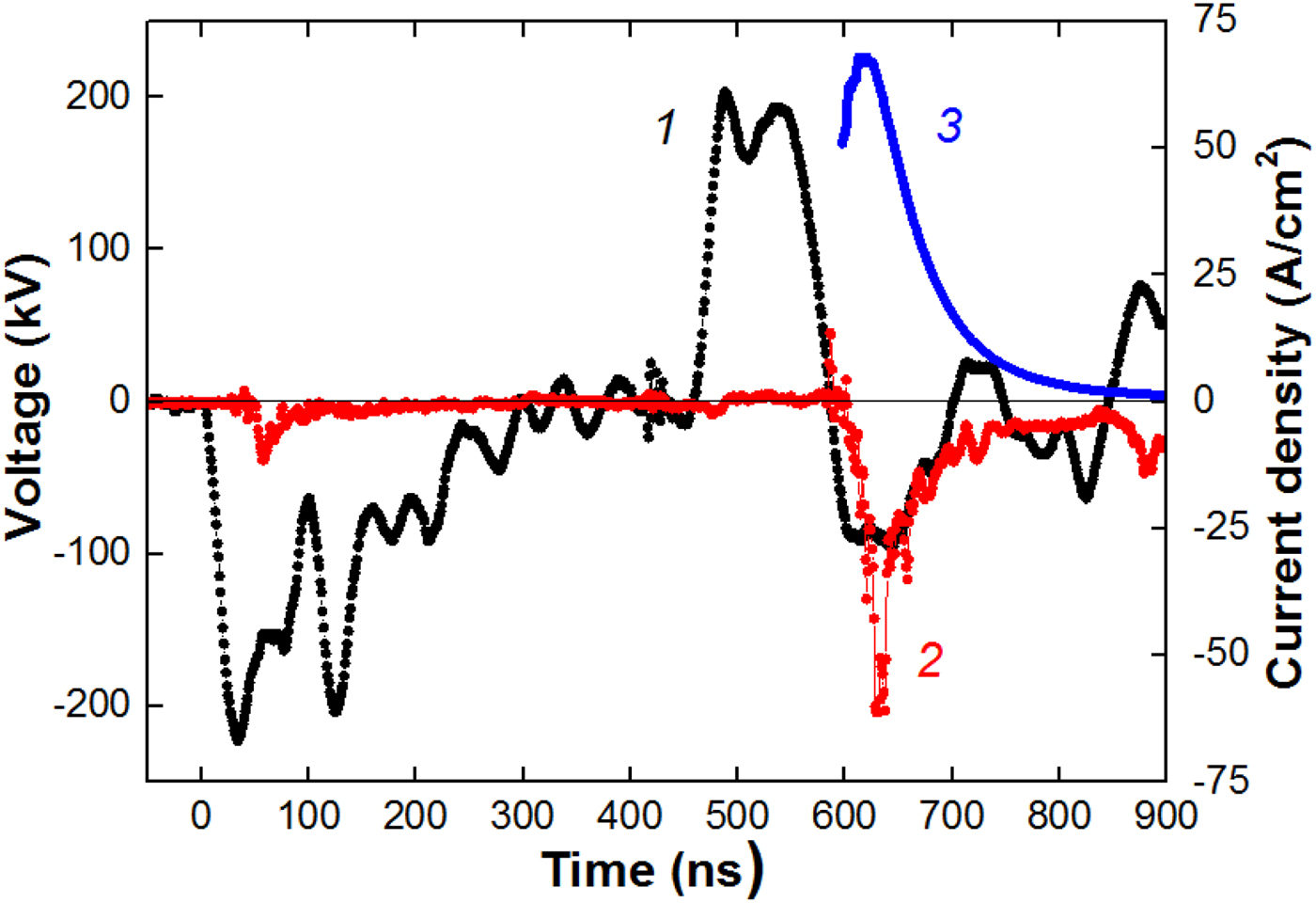
For measuring the HIPIB charge neutralization, we used a Faraday cup without magnetic field or voltage bias. That method was used by Yatsui et al. (Reference Yatsui, Sai, Masugata, Ito and Matsui1985). The diameter of the collector was 8 mm and the diameter of the hole in the lid was 4 mm. The Faraday cup was located at the distance of 14 cm downstream from the diode, in the focus. The waveforms are shown in Figure 2.
Waveforms of the accelerating voltage (1), neutralized beam current density (2), and calculated current density of С+ ions (3).
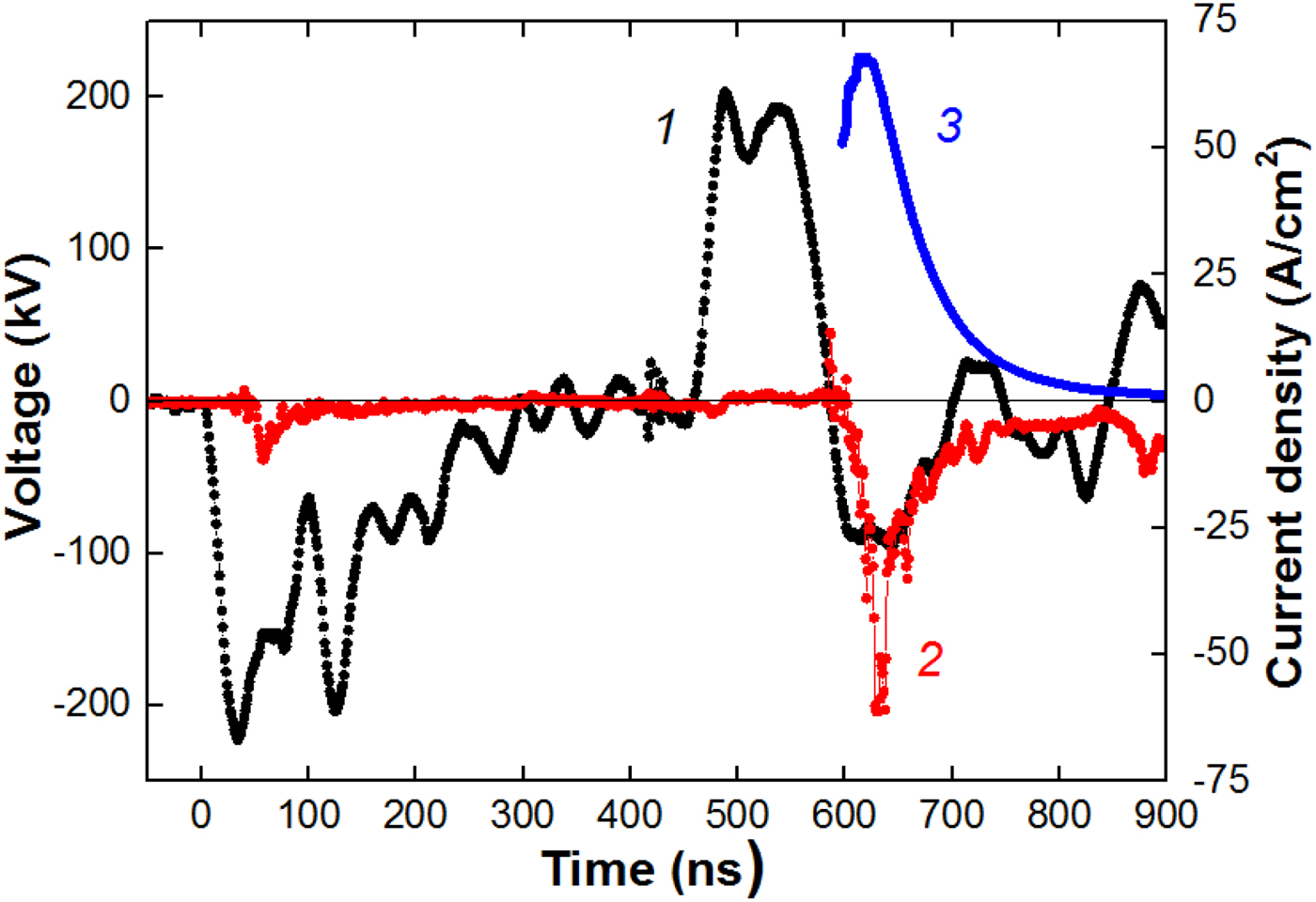
Figure 2 also shows the calculated values of the current density for C+ ions. In the space-charge limitation mode of an ion diode (Langmuir, Reference Langmuir1913) and at non-relativistic approximation, taking into account the expansion of the anode plasma and the plasma erosion effect (Pushkarev and Isakova, Reference Pushkarev and Isakova2016), the ion current density in the diode is described by:
 $$j(t) = \displaystyle{{4K{\rm \varepsilon} _0\sqrt {2z}} \over {9\sqrt {m_{\rm i}}}} \cdot \displaystyle{{U^{3/2}} \over {{[{d_0-v(t-t_0)}]}^2}},$$
where U is the accelerating voltage, d 0 is the initial A–C gap spacing, ε0 is the absolute permittivity, v is the plasma expansion velocity, m i and z are the ion mass and charge, respectively, K is the ion current amplification coefficient, t 0 is the moment when the polarity at the anode changes (t 0 = 450 ns in Fig. 2).
For each instant of the accelerating voltage (1 ns step), we calculated the current density of C+ ions and the delay of arrival of these ions to the collimated Faraday cup (CFC). The signal delay due to the ions transport from the diode to the CFC is:
 $$\Delta t = D\cdot \sqrt {\displaystyle{{m_{\rm i}} \over {2z\cdot U}}},$$
where D is the distance from the CFC to the diode.
Such technique allows for a more accurate determination of the HIPIB composition than one, which uses the delay of the maximum ion current density with respect to the maximum amplitude of the accelerating voltage (Furman et al., Reference Furman, Stepanov and Furman2007; Paperny et al., Reference Paperny, Chernih, Astrakchantsev and Lebedev2009; Yushkov et al., Reference Yushkov, Vodopyanov, Nikolaev, Izotov, Savkin, Golubev and Oks2014). The calculated values of ion current density were increased for taking into account the effect of HIPIB focusing. The enhancement factor is constant during the accelerating voltage pulse and was K = 20 for C+ ions (for Fig. 2).
The registration time of the neutralized beam current density corresponds to the ion current density recording time (see Fig. 1), which confirms the correctness of the HIPIB space charge measurement.
The performed studies showed that in the ion diode with self-magnetic insulation, the concentration of electrons in the focus is 1.3–1.5 times higher than the concentration of ions. In such diodes, ion acceleration occurs between the plasma layer on the anode surface and a layer of drifting electrons near the cathode surface. In the investigated diodes, the concentration of drifting electrons is (3–5)·1014/cm3 and the energy of those electrons does not exceed 50 keV (Zhu et al., Reference Zhu, Ding, Zhang, Isakova, Bondarenko, Pushkarev and Lei2017). At the ion current density of 40–80 A/cm2 and accelerating voltage of 250 kV, the ion concentration is (1.3–2.5)·1012/cm3. These ions pass through a dense layer of low-energy electrons, which ensures effective neutralization of the ion beam.
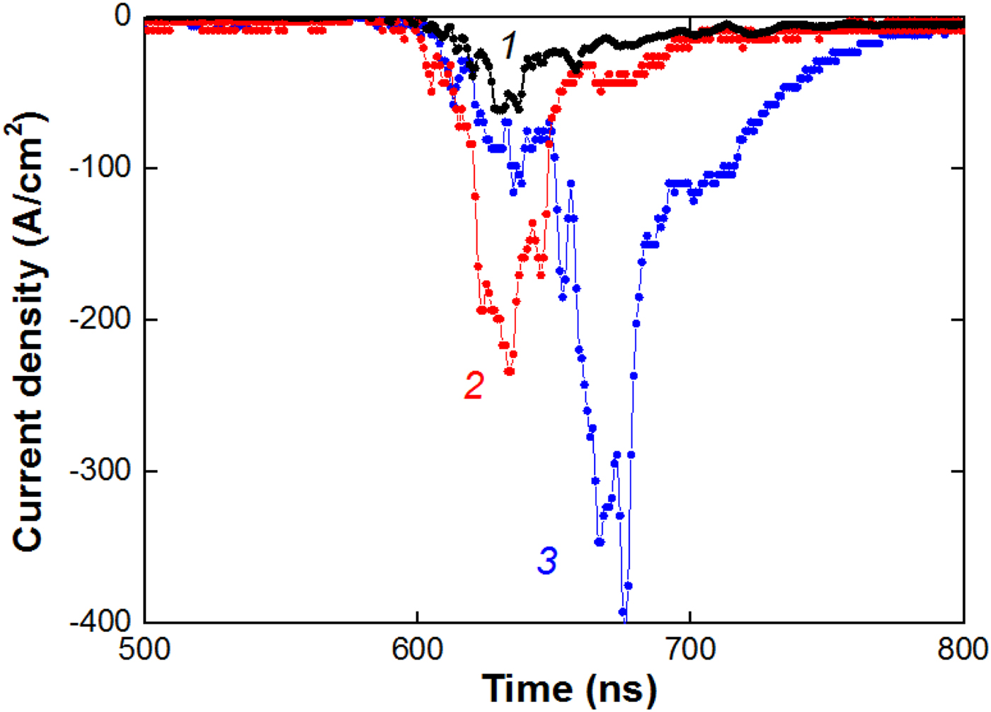
In Furman et al. (Reference Furman, Stepanov and Furman2007), it was proposed to use a metal grid to neutralize the ion beam generated by a diode with external magnetic insulation. Our research shows that a metal grid installed in the area of HIPIB focusing considerably increases the concentration of electrons in the beam (see Fig. 3 and Table 1 below).
Waveforms of the neutralized beam current density without a grid on the cathode (1), with a grid at 5 cm from the cathode (2), and two grids – one grid at 5 cm and one grid at 10 cm from cathode (3).

HIPIB parameters in the focus at different transport conditions

The density of HIPIB space charge was calculated by integrating the neutralized beam current density over time.
The performed studies showed that the concentration of low-energy electrons in the ion beam formed by a diode with self-magnetic insulation is much higher than the concentration of ions. The use of an additional metal grid in the beam transport area allows for increasing the concentration of these electrons. Formation of additional electrons is caused by secondary electron emission due to the interaction of the accelerated ions with a grid.
HIPIB focusing by its own space charge
A considerable excess of electrons concentration over concentration of ions in a beam causes occurrence of a negative charge that will cause Coulomb attraction of the ions and additional HIPIB focusing. For analysis of the influence of beam space charge on transportation of ions, we investigated HIPIB divergence and deflection of its center in the focus. For calculation of HIPIB deflection, we made a 3 mm hole in the target, see Fig. 4. The displacement of the ion beam in the focal plane was calculated as the distance from the center of the hole in the target to the point with the maximum energy density. For elimination of the ablation, we installed a stainless steel grid on the distance of 2–3 mm upstream the target. The energy density in the focus was calculated taking into account the optical transparency of this grid (50%).
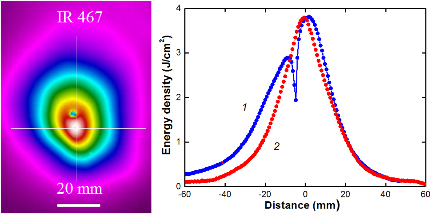
HIPIB thermal image and the energy density distribution in vertical (1) and horizontal (2) directions.

HIPIB focusing without grid
In the first set of experiments, we did not use the grid in the transport region. Figure 4 shows HIPIB thermal image on the target and distribution of the energy density. The total HIPIB energy per one pulse was 55–60 J.
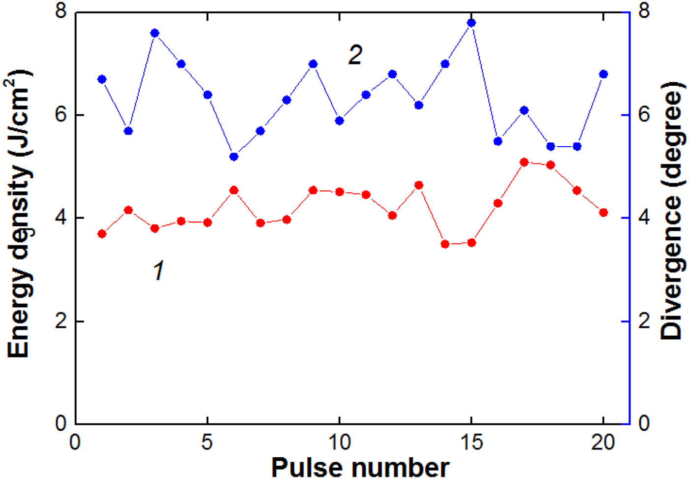
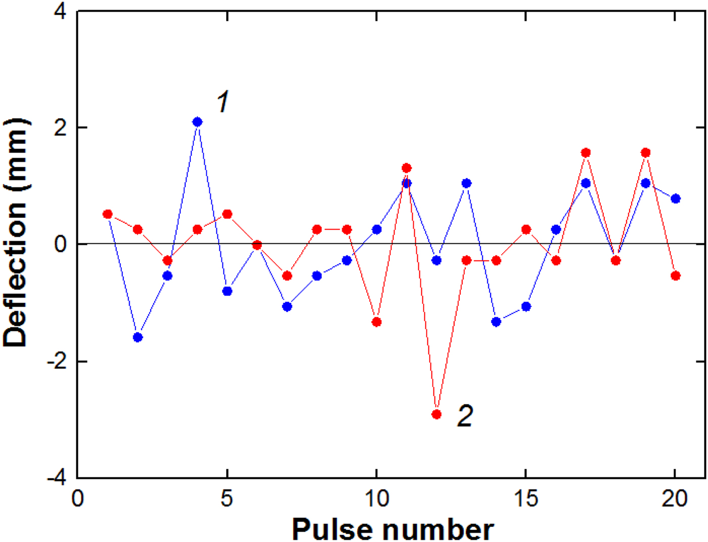
A focusing ion diode on the TEMP-6 accelerator has a semi-cylindrical geometry (see Fig. 1) and focusing occurs only in the vertical direction. However, the distribution of the energy density over the cross-section in the focal plane has an axial symmetry (see Fig. 4). This suggests that additional focusing of ions occurs by negative space charge of the beam. Figures 5 and 6 show shot-to-shot variation in the main parameters of the ion beam.
Shot-to-shot variation in the HIPIB energy density (1) and divergence in vertical direction (2) in the focus.

Shot-to-shot variation of the ion beam deflection in vertical (1) and horizontal (2) directions relatively to the average position in a series.

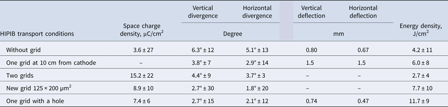
The results of statistical analysis of HIPIB parameters are presented in Table 1 (“Measurement of the beam space charge” section). The mean value in a series of pulses and the root-mean-square deviation in percentage of the average value are given. In another set of experiments, we obtained that with the pressure in the diode chamber varied from 1 to 50 mPa, the beam divergence changed insignificantly and amounted to 5.6° ± 8% (Zhu et al., Reference Zhu, Ding, Zhang, Isakova, Bondarenko, Pushkarev and Lei2017).
HIPIB focusing with the grid
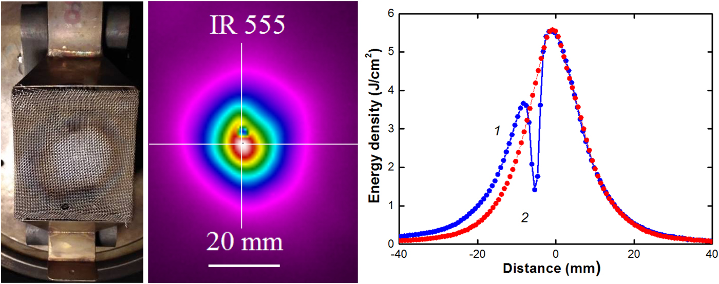
The performed studies showed that an increase in the electrons concentration in the ion beam leads to additional ion focusing, and the divergence of HIPIB decreases. Figure 7 presents the results of thermal imaging diagnostics of HIPIB, formed by a focusing diode with the metal grid (size of cell 1 mm × 1 mm, transparency 50%).
Photo of the focusing diode with the metal grid, HIPIB thermal image, and the energy density distribution in the focus in vertical (1) and horizontal (2) directions. Grid is located at 10 cm downstream from the cathode.
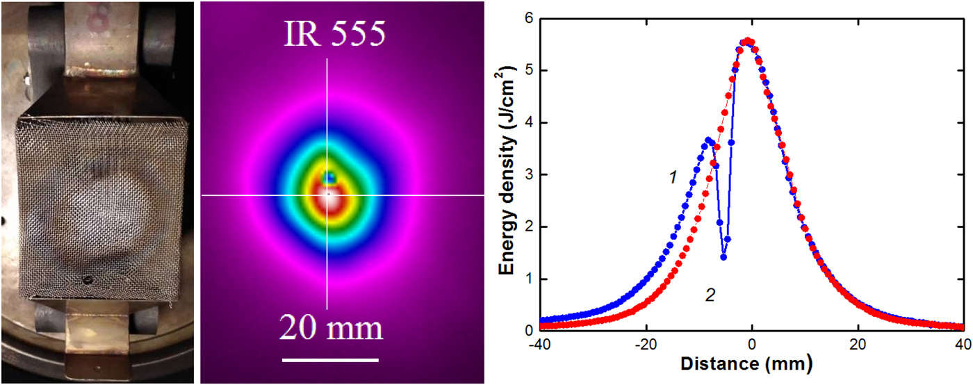
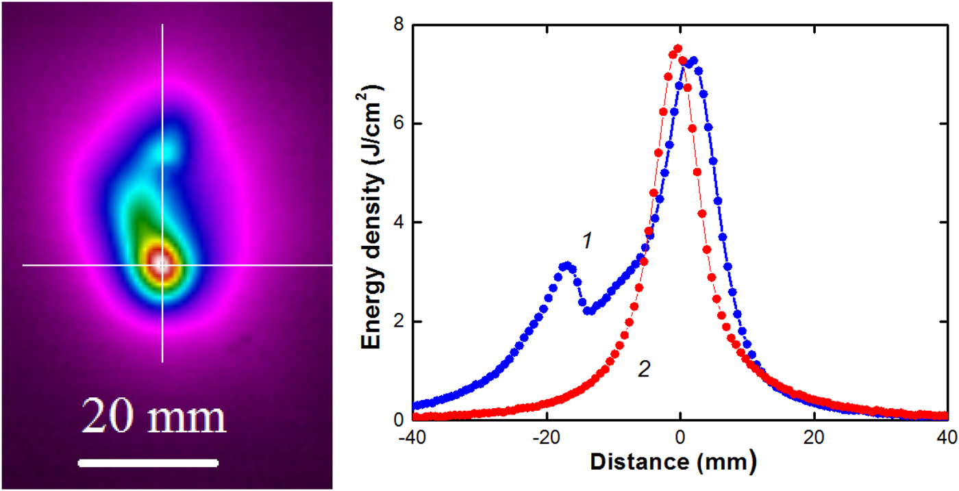
The total divergence of the beam (the sum of the divergences in the vertical and horizontal planes) decreased from 11.4° (diode without the grid) to 6.7°, this led to an increase in the energy density in the focus from 4 to 6 J/cm2 while a total energy was reduced by a factor of 2.
Reducing the spacing between wires in the grid improves HIPIB focusing, the total divergence decreased to 4.5° and the energy density in the focus increased to 7.7 J/cm2 (see Fig. 8).
HIPIB thermal image and the energy density distribution in the focus in vertical (1) and horizontal (2) directions. Grid is located at 10 cm from the cathode, size of cell 0.2 mm × 0.125 mm.
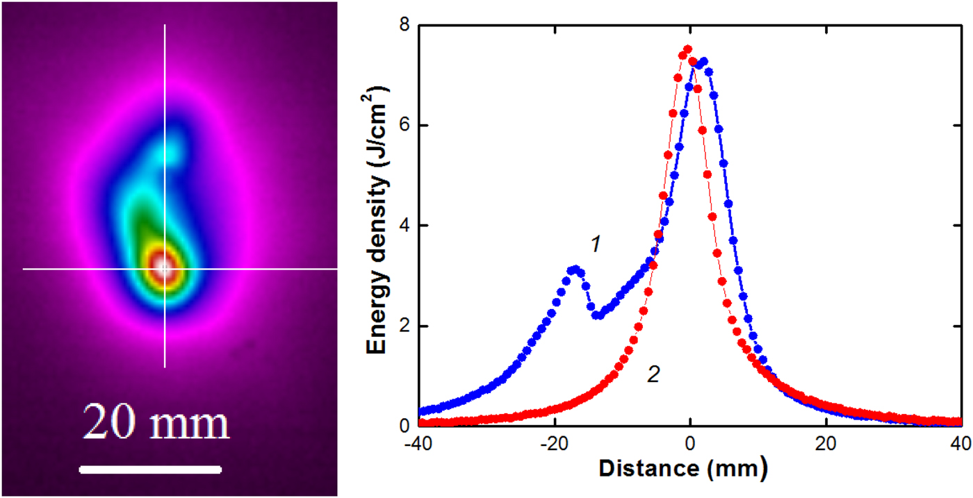
The results of statistical processing of HIPIB parameters are presented in Table 1 (“Measurement of the beam space charge” section). When using a metal grid in the focus area, the total energy of the beam decreased to 20–25 J, but the energy density in the focus increased due to additional focusing by negative beam charge. Reducing the distance from the grid to the cathode worsens the focusing of the beam by its own space charge.
Grid with a hole
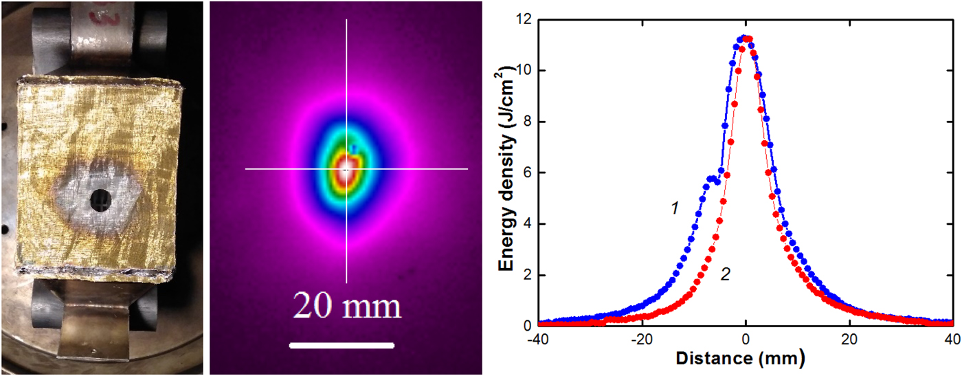
Our studies showed that for effective HIPIB focusing by its own space charge, the secondary electrons formed only by a part of the beam ions are enough. Figure 9 presents the results of thermal imaging diagnostics of HIPIB, formed by a focusing diode with a metal grid (cell of 0.2 mm × 0.125 mm) with a 14.5 mm diameter hole. This allowed us to increase the total HIPIB energy in the focal plane to 30–40 J, and the energy density to 10–12 J/cm2.
Photo of the focusing diode with the hole in the grid, HIPIB thermal imprint on the target, and the energy density distribution in the focus in vertical (1) and horizontal (2) directions (D = 12 cm).
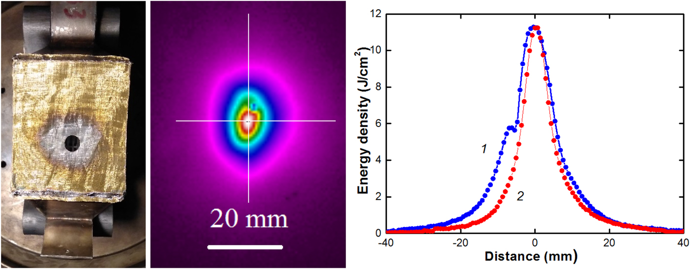
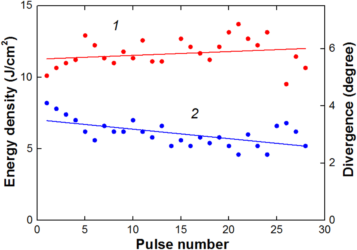
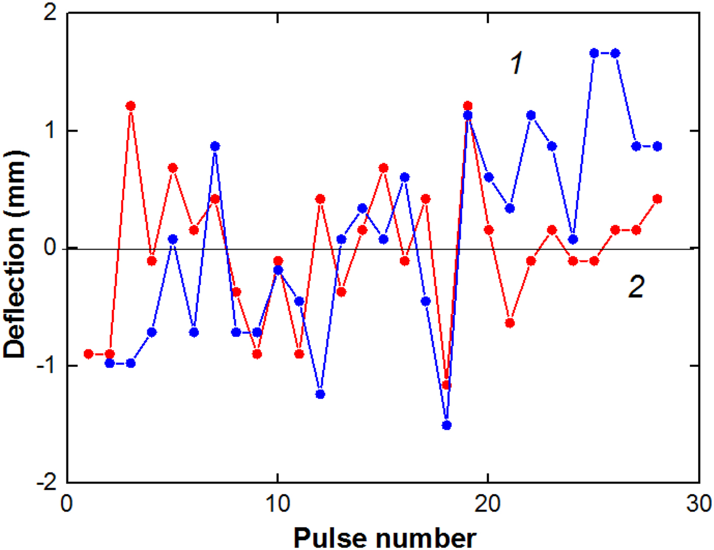
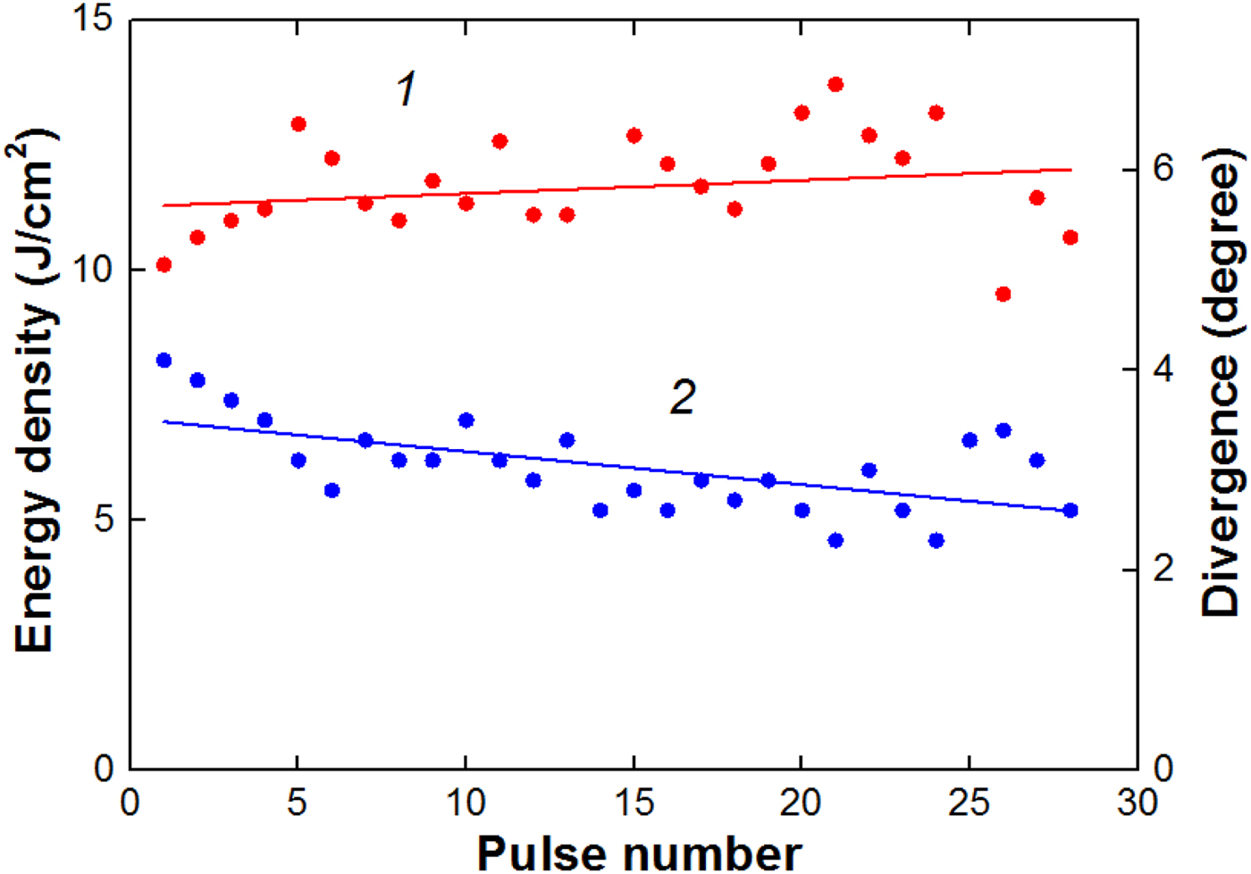
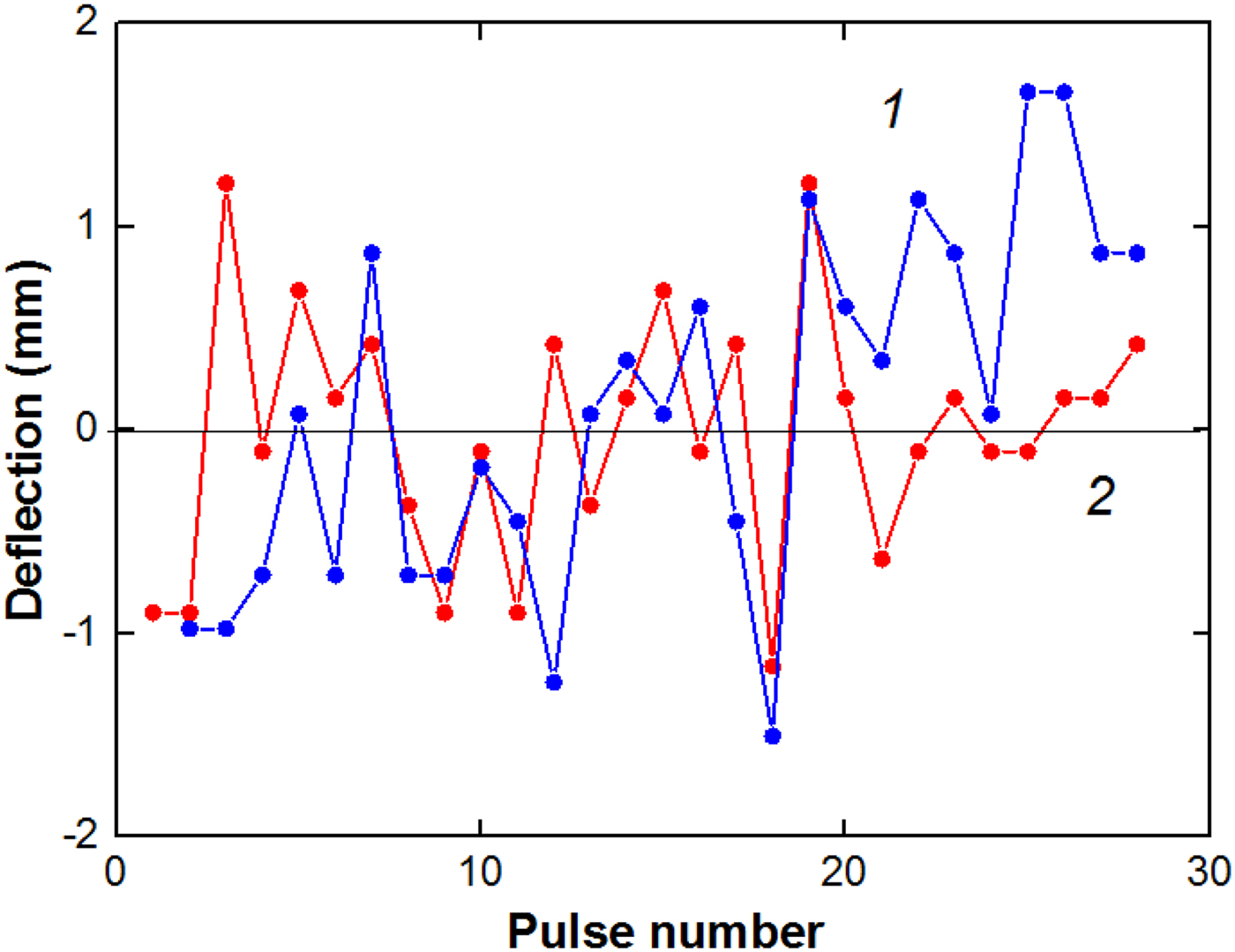
The high-energy density of the beam causes efficient ablation of the target material (the ablation threshold of stainless steel at a 150 ns pulse duration is 2.75 J/cm2) used for thermal imaging diagnostics and its deposition on the metal grid (see Figs 7 and 9). In Table 1 (“Measurement of the beam space charge” section) and Figures 10 and 11, the results of statistical analysis of HIPIB parameters formed by a diode with the metal grid with a hole in the center are presented.
Shot-to-shot variation in the HIPIB energy density (1) and divergence in vertical direction (2) in the focus.
Shot-to-shot variation in the ion beam deflection in horizontal (1) and vertical (2) directions.
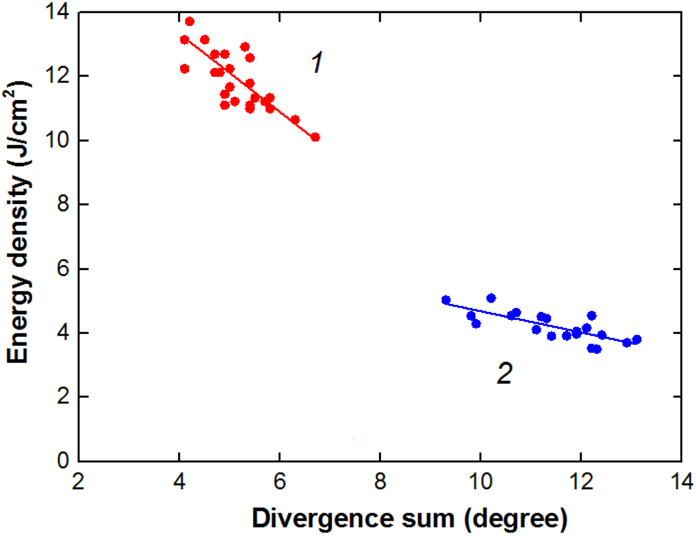
The performed studies showed that the change in the short-to-short variation in the energy density is mainly determined by a change in the beam divergence. Figure 12 shows the dependence of the energy density on the total beam divergence in the vertical and horizontal directions.
Dependence of the energy density in the focus on the beam divergence for a diode with a hole in the grid (1) and without the grid (2).

The coefficient of determination, that is, square root of the correlation coefficient, for the linear dependence of the beam energy density on the divergence was 0.58–0.60 (adjusted R 2 in the Origin 8 program). The coefficient of determination has a value in the range of from 0 to 1, by which the higher value indicates a better fitting for the dependence. Moreover, this adjusted coefficient of determination has advantage by eliminating the influence due to increasing number of variables as compared with traditional R 2 coefficient of determination.
Conclusion
(1) The performed studies have shown that HIPIB, formed by a self-magnetically insulated diode, has a net negative charge due to the excess concentration of low-energy electrons. This prevents it from scattering during focusing and causes additional space-charge compression of the beam. The increase in the density of the negative total charge (electrons and ions) of the ion beam from 3.6 to 9 µC/cm2 reduces the total beam divergence from 11.4 to 6.7°. It leads to an increase in the energy density in the focus from 4 to 7.7 J/cm2 with a decrease in the total energy by a factor of 2. To increase the electron concentration in the beam, a metal grid installed in the ion beam transport region was used.
(2) To effectively focus the ion beam by its own space charge, the secondary electrons formed by a part of the beam ions (collimated beam) are enough, so a metal grid with a hole in the area of maximum energy density can be used. For optimal hole diameter and optimal grid position in the focusing area, a total divergence of 4.5° was obtained, at the energy density in the focus of 10–12 J/cm2 and with a decrease in the total HIPIB energy by 1.5 times.
(3) An increase in the negative charge of the ion beam did not worsen the short-to-short stability of its parameters, the divergence changed by 12–15%, the displacement of the beam center in the focal plane did not exceed 2 mm. Correlation analysis showed that the change in the beam divergence from pulse to pulse is the main factor determining the stability of the energy density in the focus. The coefficient of determination of the energy density and its divergence was 0.58–0.60.
Author ORCIDs
Yu. Isakova 0000-0002-5350-2253
Acknowledgements
Analysis of experimental data and development of a model for additional ion focusing by its own space charge were supported by Russian Science Foundation via Grant No 17-79-10140. Experiments on the TEMP-6 accelerator were supported by the National Science Foundation of China under Grant Nos 51371043 and 51621064, the National Basic Research Program of China (973 Program) under Grant No 2015CB057306, the Fundamental Research Funds for the Central Universities under Grant No DUT16JJ(G)01, and High-end Foreign Experts Recruitment Program of China under Grant No GDW2017210029. The financial support from Collaborative Innovation Center of Major Machine Manufacturing in Liaoning of China and from Russian Foundation for Basic Research, project No 17-08-00067 is also acknowledged.