I. INTRODUCTION
Stretchable strain sensors can unfold opportunities in such diverse applications as flexible touch panels, structural health monitoring, and electronic skins. Reference Segev-Bar and Haick1 Compliant and conformable strain sensors emulating the tactile sensation are indispensable in realizing epidermal and wearable electronics. Such sensors can be used for accurate monitoring of health signs extracted from hardly visible movements of tissues and limbs and provide tactile sensation to brain-chip-controlled prosthetic limbs. For wearable electronics, strain sensors must have attributes such as conformability, stretchability, large-area scalability, high gauge factor, and fast response. Piezoelectric ceramic films, such as lead zirconate titanate (PZT), provide high gauge factors, Reference Dobie and Isaac2,Reference Kulha, Babchenko, Kromka, Husak and Haenen3 but have known issues for large-area processability, rigidity, and bioincompatibility. While high piezoelectric coefficients are reported for single nanowires (NWs) and nanotubes (NTs), Reference Kon, Oldham and Horowitz4,Reference Wu, Chen, Zhang, Chen, Yang, Hu, He and Wang5 practical large scale meshes of carbon NTs Reference Riekeberg, Buttner and Muller6–Reference Su, Liu, Chang, Wang and Chang14 and NWs Reference Takei, Takahashi, Ho, Ko, Gillies, Leu, Fearing and Javey15 and composites of NTs, Reference Hu, Karube, Arai, Watanabe, Yan, Li, Liu and Fukunaga16–Reference Hu, Karube, Yan, Masuda and Fukunaga20 graphene, Reference Lee, Bae, Jang, Jang, Zhu, Sim, Song, Hong and Ahn21 and carbon particles Reference Cochrane, Lewandowski and Koncar22,Reference Mattmann, Clemens and Troster23 have shown limited gauge factors and/or slow responses. For instance, aligned bundles of carbon NTs on elastomer substrates Reference Yamada, Hayamizu, Yamamoto, Yomogida, Izadi-Najafabadi, Futaba and Hata13 have been reported with 280% stretchability and a maximum gauge factor of 0.82.
This work presents for the first time high gauge factor piezoresistive meshes of core–shell nanofibers (NFs) fabricated using a scalable electrospinning process. Mimicking the fibrous structure of natural tissues, the NF meshes exhibit high flexibility/stretchability, conformability to curvilinear surfaces, as well as fast, low voltage, and repeatable response to both tensile and compressive strains. The high gauge factor of the mesh, comparable to piezoelectric ceramics, is attributed to a reversible disjointing/jointing mechanism among numerous interfiber junctions that are held together by a surrounding elastic matrix. We demonstrate the applications of the NF textile sensor for epidermal health monitoring, showing exceptional performance for monitoring muscle movements, accurate detection of radial pulse, and real-time monitoring of simulated intermittent Parkinson's tremors. An electronic sensor array is demonstrated for the measurement of biaxial components of planar strain fields for tactile applications.
II. EXPERIMENTAL
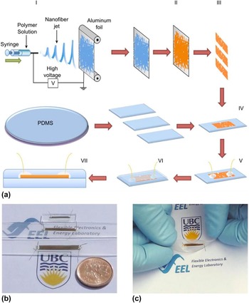
The fabrication steps of core–shell NF mesh sensors are illustrated in Fig. 1(a). In step I, a 10 wt% solution of polyacrylonitrile (PAN, MW 100,000 g/mol, Scientific Polymer Products) in dimethylformamide (DMF) (99.9%, Fisher Scientific), stirred at 60 °C for 24 h, was loaded into a syringe with a blunted G18 needle in an electrospinning unit (Kato Tech Co., Kyoto, Japan) to deposit the nanofibrous mesh on a grounded collector (aluminum foil) at a flow rate and a voltage of 0.6 mL/h and 17 kV, respectively. In step II, a thin conformal gold shell is sputtered (Edward Sputter Coater) on the NF mesh template. The active ribbons of NF mesh with a desired dimension (e.g., 3 mm wide and 10–50 mm long) are cut (step III) and transferred (step IV) to the surface of a flat polydimethylsiloxane (PDMS) substrate, with a thickness of ∼1 mm. Electrical contact pads are prepared (step V) by the application of silver paint (Ted Pella) to both ends of the NF mesh. A PDMS layer is poured (step VI) on the top of the NF mesh and the sample is placed in a desiccator and evacuated by a rotary pump to remove the trapped gas bubbles and obtain a uniform composite, followed by a curing step (VII) at 90 °C for 45 min.
Fabrication process of core–shell NF meshes. (a) Schematic of the fabrication steps of the encapsulated core–shell NF mesh sensors: (I) Electrospinning of PAN NFs, (II) sputtering a thin gold shell using NF mesh as a template, (III) cutting active ribbons of NF mesh, (IV) transferring the ribbons to a PDMS substrate, (V) deposition of electrical contacts, (VI) encapsulation with the top PDMS layer, and (VII) curing the sensor. (b and c) Photographs of typical samples showing dimensions and flexibility of piezoresistive NF sensors.

For uniaxial strain testing, a sensor is clamped on one end and a motorized actuator (Zaber T-LSM 28) with a positioning accuracy of less than 1 µm moves the other end. The electrical contacts of the sensors are connected to a Keithley 2400 Sourcemeter, which supplies a voltage and measures the current changes with time. The current measurements are synchronized with the movement of the actuator using a LabView program. Vibrational monitoring experiments are performed by laminating a sensor device on a thin rigid spring steel blade (∼300 mm long, 25 mm wide, and 1.5 mm thick) fixed from one end in a vice clamp. The oscillations of the free end of the blade in response to an initial deflection are used for the generation of controlled vibrations in a cantilever deflection setup. The current changes for the sensor biased with a constant voltage are recorded using a data acquisition system (National Instrument, NI 6525) and the electrical measurement setup discussed before. A similar steel blade setup (here ∼300 mm long, 25 mm wide, and 1.5 mm thick) is used to study the temperature-dependence of the sensor response. The temperature of the sensor is controlled using a flexible heater attached on the opposite side of the blade with respect to the sensor. The heater is connected to a temperature-controller (Digi-Sene 89000) equipped with a thermocouple to set the desired temperature T. The free end of the blade is deflected by δ in either directions to apply tensile or compressive strains ε. The source meter is used to measure the electrical resistance of the sensor as a function of the mechanical deflection at different temperatures. Tactile and pulse sensing and musculoskeletal monitoring are performed by attaching single or multiple sensors to epidermis using a double-sided tape. The sensor is attached to the ventral side of the forearm in the midproximal of the flexor bundle, 10 cm distal from the elbow, parallel to the arm direction for limb movement measurements, and directly on the radial artery for radial pulse and simulated intermittent Parkinson's tremor measurements. The sensor response to body movement and pulse is measured using the NI 6525 system.
III. RESULTS AND DISCUSSION
Figure 1(a) illustrates the fabrication process, which was described in detail in the Experimental section, followed by digital photographs of the as-prepared sensors of different sizes showing their soft and compliant nature in Figs. 1(b) and 1(c). Figure 2 depicts scanning electron microscopy (SEM) images of the NF textiles and sensors. Figures 2(a) and 2(b) show the microstructure of the NF mesh consisting of several layers of randomly placed fibers and displaying the nanostructured surface of the gold-coated NFs. SEM images demonstrate that NFs have an average diameter of ∼400 nm with a standard deviation of ∼20 nm and a uniform conformal coating is achieved by gold sputtering on the surface of the NFs. The formation of inter-NF junctions between overlapping fibers is displayed in Figs. 2(c) and 2(d). The electrical resistance of the mesh depends on the density of NFs and the thickness of the gold layer. For typical sample sizes, this is low and in the order of a few Ohms to hundreds of Ohm, which can be attributed to the continuous shells and the low inter-NF junction resistances, as compared to the other reported NT and NW sensors with high junction resistances. The unprecedented combination of low resistance and high gauge factor makes these sensors ideal for accurate strain-sensing applications.
SEM micrographs of gold-coated core–shell NF mesh before transferring to PDMS. (a) A thick layer consists of multiple levels of NFs. (b) High-magnification cross-sectional SEM image of the core–shell NF mesh in a resin mold, demonstrating a tubular continuous gold shell formed for core–shell NFs. (c and d) Higher magnification SEM micrograph of the core–shell NF mesh, illustrating the nanostructured surface of gold shell and formation of a large number of inter-NF junctions.

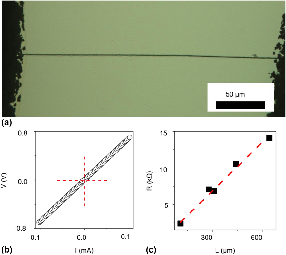
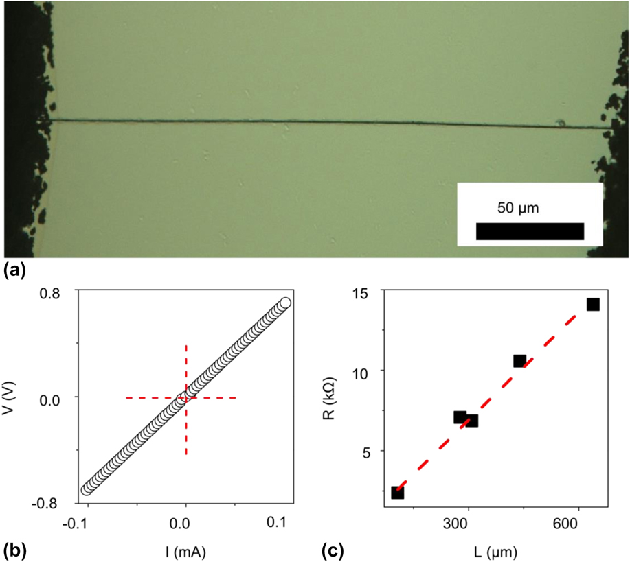
Figure 3(a) illustrates the photomicrograph of a single Au-coated NF on a glass substrate between two silver paint contacts. The typical current–voltage (I–V) characteristics measured for this NF are demonstrated in Fig. 3(b), indicating an Ohmic behavior for the NF. To verify the uniformity of the conductive shell along the NF length, five single NF samples with different lengths are examined. The change in the resistance of the NF as a function of sample length is presented in Fig. 3(c). The linear relationship between the resistance and the length of the segment under measurement (about 25 Ω/µm) confirms good uniformity of the diameter of NFs and the metallic shell. This indicates a resistivity of about 10 times that of bulk gold for the shell, possibly due to the nanostructured shell morphology.
(a) Photomicrograph of a single Au-coated NF between two silver contacts. (b) Current voltage (I–V) characteristics of the NF showing an Ohmic behavior. (c) The measured resistance of NFs as a function of length for five different single NF samples, having different separations between contacts, illustrating the linear scaling of the resistance with length, signifying the uniformity of the conformal coating.
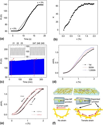
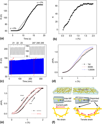
Figures 4(a) and 4(b) illustrate the measured resistance and gauge factor K of the strain sensor in response to an increasing uniaxial tensile strain from 0 to 2%. For strains below 1%, the gauge factor increases linearly and stabilizes to a maximum value of >60 for strains above 1%. Figure 4(c) depicts the response over 1000 stretching cycles, demonstrating the durability of the sensors. The variations of ΔR/R
0 versus strain are depicted in Fig. 4(d) for the first, 500th, and 1000th cycles. The sensor shows a remarkably stable response with only 6.4% increase in ΔR/R
0 at 2% strain after 1000th cycles, which can be attributed to the plastic relaxation of the PDMS matrix. Figure 4(e) represents the relative changes in the resistance
 $\left( {{{R - {R_0}} \over {{R_0}}}} \right)$
of the sensor as a function of the applied strain for the rates of 0.2 and 0.5% per second during both loading (extension) and unloading (contraction) cycles. No significant differences are observed between the responses at the two different strain rates. The small hysteresis between loading and unloading can be attributed to the relaxation of the PDMS matrix. The tensile strain displaces the NFs, hence disjointing some of the inter-NF junctions and increasing the current path and the overall resistance of the mesh, Fig. 4(f). The strain is mainly accommodated by reorientation of the NFs, thus alleviating the formation of microcracks in the shells of the individual NFs. The NF mesh can be modeled as a large number of switches that are gradually disconnected with increasing tensile strains, increasing the resistance of the network. The encapsulating elastomer acts as an elastic spring, providing reversibility for a disjointing/jointing mechanism.
(a) Measured resistance of the NF sensor as a function of time in response to the changing strain (dashed line) from 0 to 2% at a constant speed of 0.2% per second. The sensors lose their reversible stability beyond 2–3% strain, due to permanent disruption of the contact between NFs and silver electrodes. (b) The extracted gauge factor K as a function of strain, showing a gauge factor in excess of 60. (c) The repeatability of the strain sensor response over 1000 uniaxial stretching cycles (the insets show the close-ups of the curve at two different intervals near the beginning and close to the end of the experiment). (d) Relative change in the resistance for the first, 500th, and 1000th cycles. (e) Relative changes in the resistance of the sensor during stretching cycles with two different speeds 0.2 and 0.5%/s. (f) Schematic of the core–shell NF mesh in the relaxed and stretched cases, showing the mechanism for the observed response to strain. The tensile strain disjoints some inter-NF junctions along the current path, increasing the length of the path and the effective resistance of the mesh. The elastomer matrix holds the inter-NF junctions in place like a spring, resulting in a reversible disjointing/jointing mechanism.

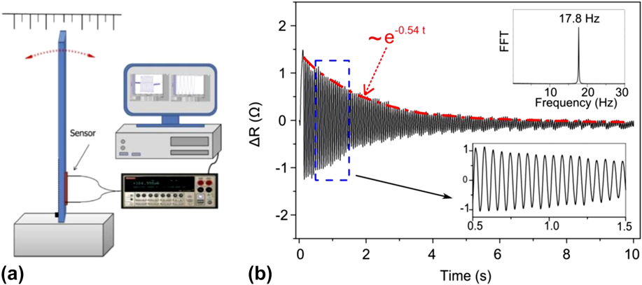
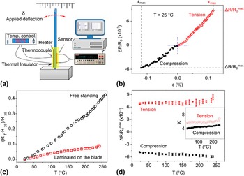
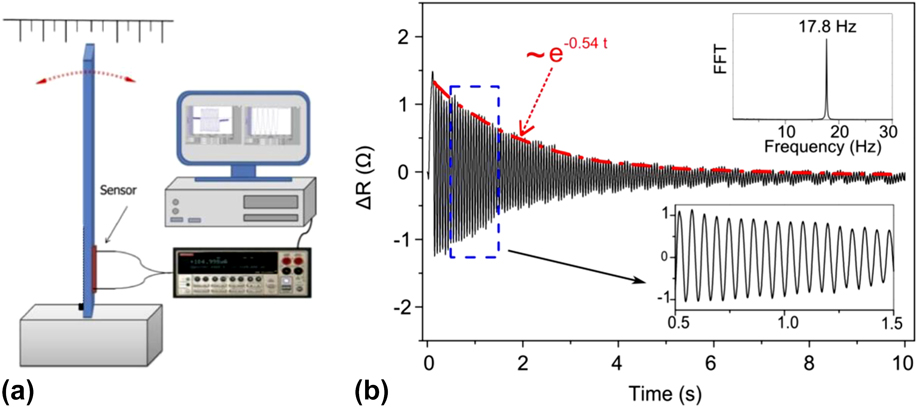
The dynamic response of a NF sensor laminated on a steel cantilever is reported in Fig. 5. As explained in the Experimental section, the sensor was laminated on the surface of a cantilever beam of spring steel. The oscillation of the free end of the cantilever is detected by measuring the changes in the resistance of the sensor. Figure 5(b) shows the response of the sensor to the damped natural vibrations of the blade. As can be seen in the inset of Fig. 5(b), the extracted natural frequency of oscillation is centered at around 17.8 Hz (with a bandwidth of ∼0.2 Hz at −3 dB) by looking at the Fast Fourier Transform (FFT) of the measured signal. This value is consistent with the expected first bending mode natural frequency of the steel blade (18.6 Hz), which is calculated using the dimensions and physical properties of the blade. In addition, it can also be observed that the envelope of the measured signal is an exponential decay function (the red dashed line in Fig. 5) with a damping coefficient of γ ∼ 0.54 s−1. Using this value, the damping factor of the blade is calculated to be ζ ∼ 0.0047, which further demonstrates the underdamped oscillation nature of the vibrating blade. The recorded vibrational response is indicative of the fast response of the NF sensor to both tensile and compressive strains and does not indicate the upper frequency of operation. Figure 6(b) illustrates the relative changes in the resistance ΔR/R 0 in response to static deflections of the blade [as pictured in the experimental setup in Fig. 6(a)] for applying tensile and compressive strains ε in the range of +0.12% to −0.12%. For the maximum magnitudes of the applied strain [indicated by εmax in Fig. 6(a) for both tensile and compressive strains], the resulting relative change in the resistance of the sensor, ΔR/R 0 max, is 0.9% and −0.6%, corresponding to the room temperature gauge factor (K) values of ∼7.2 and ∼4.7 for tensile and compressive strains, respectively. The temperature-dependence of the strain sensitivity is also studied in two steps. Figure 6(c) shows the effect of the temperature on unstrained sensors. The relative change in the resistance caused by heating from room temperature to a higher temperature is demonstrated as a function of temperature for a sensor laminated onto a steel blade, as well as a freestanding sensor. Increasing the temperature to 240 °C increases the resistance of the freestanding sensor far more (42%) in comparison with (8.5%) the laminated one. This could be explained in view of an order of magnitude lower thermal expansion coefficient of steel as compared to PDMS, thus preventing the laminated sensor from expanding as much as its freestanding counterpart. In the second step, the effect of the temperature on the strain sensitivity of the sensors is studied, by conducting experiments similar to the one shown in Fig. 6(b) at temperatures varying from the room temperature to 240 °C. The values of the relative change in the electrical resistance under the maximum tensile and compressive strains, ΔR/R 0 max, are plotted against temperature in Fig. 6(d). It is observed that upon heating, the ΔR/R 0 max increases slightly from 0.66% at room temperature to 0.77% at 240 °C, in tensile mode, and from 0.48 to 0.59%, in compressive mode. This slight increase in the sensitivity of the sensor can be attributed to the increase in the elastic modulus of the PDMS elastomer, due to further cross-linking at higher temperatures, which decreases the compliance of PDMS matrix, causing the disjoining of NF junctions to happen at lower strain levels.
(a) A schematic of the placement of sensor on one side of a vibrating clamped beam for testing the dynamic response of the sensor. (b) The measured change in the resistance of the sensor showing damped oscillations of the sensor laminated on the surface of the vibrating beam. A close-up of the graph and FFT of the recorded signal are shown in the insets.
(a) The schematic of the measurement setup used to test the electromechanical response of the sensor at different temperatures. (b) The variations in the relative change in the electrical resistance of the sensor at room temperature under a range of positive (compressive) and negative (tensile) blade deflections. (c) The relative change in the electrical resistance of a freestanding sensor as well as one laminated on a steel blade with varying temperature under no strain. (d) The response of the sensor laminated on the blade to the desired applied strain [denoted by εmax in (b)] at different temperatures. The response is measured for both compressive and tensile applied deflections.

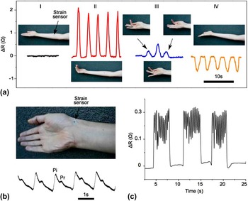
The soft and compliant nature of the NF sensors highlights their suitability for epidermal and wearable electronic. Reference Hemmerling and Le24,Reference Bonato25 Figure 7(a) illustrates the monitoring of the flexion and extension movements of fingers using a sensor attached to the “flexor bundle” of the forearm. As shown, in contrast to a relaxed hand (I), the flexions of all four fingers (II) cause abrupt increases in the resistance of the sensor (indicative of tensile strain due to the enlargement of the bundle). One-by-one flexions (III) of each finger generate the highest response for the flexion of the third finger, since the sensor is placed on the flexor bundle mainly responsible for the flexion of this finger. The same sensor reacts to the extension of all four fingers (IV) with a decrease in the resistance (indicative of compressive strain caused by extension of the bundle, needed to provide the range of motion). Reference Van Duinen, Yu and Gandevia26,Reference Abbruzzese, Morena, Spadavechia and Schieppati27 The ability of the sensors to accurately detect flexions and extensions is critical for clinical applications, as muscle injuries occur more often during extensions. Reference McCully and Faulkner28,Reference Widrick and Barker29
(a) The response of a NF sensor adhered to epidermis to contractions of the flexor bundle of the forearm muscles (mainly consists of flexor digitorum superficialis and flexor digitorum profundus) for four different gestures: (I) the neutral hand position (the baseline), (II) repeated flexion and release of all four fingers, (III) subsequent flexion of the second, third and fourth digits, and (IV) the repeated extension of all four fingers. (b) The response of the sensor adhered on the wrist for monitoring the radial pulse, showing a rate of 65 beats per minute and distinguishable systolic incident wave (Pi) and diastolic reflected wave (Pr). (c) The response of the sensor placed at a similar position as that of part (a) to simulated intermittent Parkinson's tremors.

Figure 7(b) illustrates the real-time monitoring of radial pulse using a sensor attached directly on the radial artery. The resting pulse rate is around 65 beats per minute. The measured waveform shows an early systolic peak (Pi), produced by forward ejection of blood along a direct pass from left ventricle to the hand, followed by a later peak (Pr), occurring in early diastole due to the wave reflected from points of impedance discontinuity such as arterial branching and arterial–arteriolar junctions. This is consistent with the well-established methods such as pulse-wave analysis (PWA) and pulse-wave velocity (PWV) measurements. Reference Millasseau, Kelly, Ritter and Chowienczyk30,Reference Hirata, Kawakami and O'Rourke31 Figure 7(c) illustrates the response of the sensor placed on the forearm during simulated intermittent Parkinson's hand tremors, to demonstrate the applications for noninvasive and accurate health monitoring.
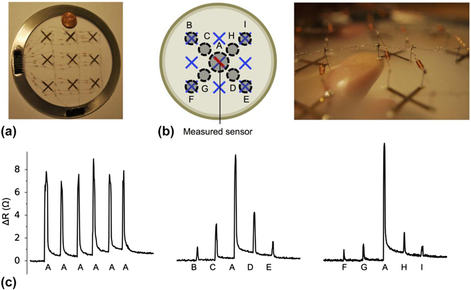
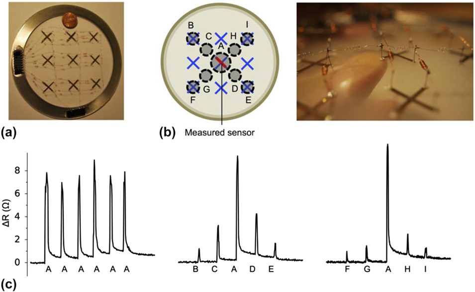
Figure 8(a) illustrates a 3 × 3 array of strain sensors, fabricated for tactile skin applications. Two sensors in a form of a cross are fabricated at each point, separated by a PDMS interlayer, allowing measurement of biaxial components of a planar strain field at each point. The response of the central sensor (CS) to tapping at different locations of the tactile skin [Fig. 8(b)] is plotted in Fig. 8(c), for three different sequences: six consecutive taps at the center (AAAAAA) on top of the CS, five equally spaced taps from the top-left to the bottom-right (BCADE), and five equally spaced taps from the bottom-left to the top-right (FGAHI) of the array. The change in the resistance of the CS to “A” taps has the maximum magnitude, indicating the highest observed tensile strain. The response is lower in magnitude but symmetric for tapping at centrosymmetric location pairs, i.e., CD, BE, GH, and FI. The responses for pairs located in the direction of the current flow (CD and BE) are larger than those for pairs located in the perpendicular direction to the current flow (GH and FI) of the sensor.
(a) Photograph of a 3 × 3 array of sensors, fabricated with two sensors, separated with a PDMS film, forming a cross at each point of the array. (b) Use of this electronic skin array for tactile sensing. (c) The response of the sensor in the middle of the array (colored in red, pointing from the top left to the bottom right of the array) to a series of taps by finger at different locations of the array: (i) Six taps at the center (AAAAAA) of the array on top of the sensor, (ii) five taps equally spaced from the top left corner to the bottom right corner (BCADE) of the array, and (iii) five taps from the bottom left corner to the top right corner (FGAHI) of the array.
IV. CONCLUSIONS
We report for the first time a nature-inspired, compliant, strain-sensing nanofibrous mesh, exhibiting an unprecedented gauge factor of >60 and a repeatable response. The strain-sensitivity is attributed to the reversible disjointing/jointing of inter-NF junctions held together by a spring action of the encapsulating elastomer. High-aspect-ratio metallized core–shell electrospun NFs provide a stable low resistance comparable to that of metallic gauges and a high gauge factor often seen for high-performance piezoelectric sensors, suitable for accurate structural health monitoring. The soft sensing skin is attached to epidermis for monitoring muscle movements, radial pulse, and simulated intermittent Parkinson's tremors. Tactile sensing is demonstrated for an array of NF strain sensor devices that measure biaxial components of a planar strain field. This signifies the applications of this scalable technology to wearable electronic health monitoring systems and tactile and vibrational sensing.
ACKNOWLEDGMENTS
The authors would like to acknowledge the support of Natural Sciences and Engineering Research Council (NSERC) of Canada, Canadian Foundation for Innovation (CFI), the University of British Columbia, U.S. Air Force Office of Scientific Research (AFOSR)’s Multiuniversity Research Initiative (MURI) program, and Stanford University.