


1. INTRODUCTION
Tape-helix type high power pulse accelerator is in hot applications in the fields of high power microwave radiation (Korovin et al., Reference Korovin, Kurkan, Loginov, Pegel, Polevin, Vollkov and Zherlitsyn2003), high power pulse laser (Sethian et al., Reference Sethian, Myers and Giuliani2005; Hegeler et al., Reference Hegeler, McGeoch, Sethian, Sanders, Glidden and Myers2011), X-ray radiography (Mesyats et al., Reference Mesyats, Korovin and Rostov2004), dielectric barrier discharge (Panousis et al., Reference Panousis, Merbahi, Clement, Yousfi, Loiseau, Eichwald and Held2009), processing of industrial exhausted water and gas (Shimomura et al., Reference Shimomura, Nakano, Nakajima, Kageyama and Teranishi2011; Hartmann et al., Reference Hartmann, Roemheld, Rohde and Spiess2009 ), material surface processing (Zhan et al., Reference Zhan, Li and Xu2007), ozone production (Kogelschatz et al., Reference Kogelschatz2003), food sterilization (Laroussi et al., Reference Laroussi2005), and underwater electrical wire explosion. In order to obtain load voltage pulse with amplitude as the charging voltage, the Blumlein type pulse forming line (PFL) is in common use (Teranishi et al., Reference Teranishi, Nojima and Motegi1991; Liu et al., Reference Liu, Li and Zhang2006; Liu et al., Reference Liu, Yin and Ge2007; Liu et al., Reference Liu, Zhan and Zhang2007; Liu et al., Reference Liu, Cheng and Qian2009; Cheng, Liu, Qian, et al., Reference Cheng, Liu, Qian and Zhang2009; Cheng, Liu, Zhang, et al., Reference Cheng, Liu and Zhang2009). In order to avoid additional unwanted effects on the characteristic parameters, the tape helix is usually very thin (<1 mm). As a result, the tape helix is not strong enough and air-core cylindrical insulator should be introduced in the system to support the tape helix (Zhang, Liu, Wang, et al., Reference Zhang, Liu, Fan, Zhang, Wang and Feng2011). The air-core cylindrical insulator with small thickness has different permittivity from the previous filling dielectric in the PFL. So, different permittivities cause dielectric discontinuity inside the PFL in the radial direction, and this mechanism has great effects on the characteristic parameters (including the impedance) of the helical BPFL (Zhang, Liu, Wang, et al., Reference Zhang, Liu, Wang, Fan, Zhang and Feng2011).
A key point for helical BPFL design is the impedance matching between the inner line and outer line of the BPFL. Otherwise, the load voltage pulse consists of several discontinuous ladder sections that are caused by the repetitive reflections of electromagnetic wave at the side of the PFL (Liu et al., Reference Liu, Cheng and Qian2009; Cheng, Liu, Qian, et al., Reference Cheng, Liu, Qian and Zhang2009; Cheng, Liu, Zhang, et al., Reference Cheng, Liu and Zhang2009). The helical BPFL is a kind of dispersive pulse delay line (Kompfner, Reference Kompfner1947; Sichak, Reference Sichak1954; Kino et al., Reference Kino and Paik1962). The common used “quasi-static” theory (Kompfner, Reference Kompfner1947; Sichak Reference Sichak1954; Kino et al., Reference Kino and Paik1962; Lewis et al., Reference Lewis and Wells1959) and the “traveling wave method” based on telegraphers' equations (Cheng, Liu, Qian, et al., Reference Cheng, Liu, Qian and Zhang2009; Cheng, Liu, Zhang, et al., Reference Cheng, Liu and Zhang2009) can be employed to calculate the characteristic impedance of the helical PFL. However, these methods do not consider the effects of dispersion on the impedance matching condition of the BPFL, so that they have difficulty to accurately analyze the impedances of helical BPFL. In contrast to the aforementioned methods, the tape-helix boundary conditions (Sensiper, Reference Sensiper1951, Reference Sensiper1955) can be introduced in the fields of helical PFL to accurately analyze the characteristic impedances and the impedance matching condition of the helical BPFL.
The reference (Zhang, Liu, Wang, et al., Reference Zhang, Liu, Fan, Zhang, Wang and Feng2011) employed the tape-helix boundary conditions to analyze the effects of dielectric discontinuity on the dispersion characteristics of the uni-filar tape-helix BPFL. In this paper, the spatial harmonics and dispersion of multi-filar tape-helix BPFL of the electron accelerator are analyzed by the tape-helix dispersion theory. The most important topic of this paper focuses on the characteristic impedances and impedance matching condition of the helical BPFL based on the multi-filar tape helix. The effects of dispersion and dielectric discontinuity on the impedance matching condition are also analyzed. Many valuable conclusions are obtained and they show great value on further study of tape helix slow-wave structure in helical BPFL and long pulse accelerator.
2. SPATIAL HARMONICS ANALYSIS OF THE MULTI-FILAR TAPE-HELIX BPFL
Figure 1 shows the geometric structure of a three-filar tape helix slow-wave system that consists of an outer shield, tape helix, an inner shield, air-core cylindrical nylon support dielectric, and filling dielectric. Three narrow tapes with 120° between each other in the azimuthal direction, curl in the same way along the axial direction. The system is symmetric and periodic in the azimuthal direction and the axial direction. The “infinitesimally thin” tape-helix approximation is adopted in this paper. Cylindrical coordinates (r × θ × z) are established along the axial direction (z) as Figure 1a shows. r and θ represent the radial and azimuthal direction, and r 1, r 2, r 3 represent the radii of the inner shield, tape helix and the outer shield, respectively. The inner and outer radii of the support dielectric are a and r 2. ψ is the pitch angle of tape helix, while the pitch and tape width are p and δ, respectively. l 0 is the length of the “infinitesimally thin” tape in the axial direction. As Figure 1b shows, the filling dielectric and the support dielectric (nylon) have different relative permittivities as ɛr1 and ɛr2, so dielectric heterogeneity phenomenon in the radial direction occurs. The geometric parameters of the three-filar tape helix are shown in Table 1.
(Color online) The three-filar tape helix slow-wave system with a cylindrical support, filling dielectric and two metal shields (a) Geometric structure of the three-filar tape-helix BPFL (b) Cross section of the slow-wave system.

Geometric parameters of the three-filar tape-helix BPFL with discontinuous filling dielectrics

In an “infinite long” uni-filar helical slow-wave system (or l 0 >> r 2), the electromagnetic field excited in the slow-wave system is in periodical and symmetric distribution. In other words, if the observer has a displacement p along the z direction or has an angular displacement of 360° in the azimuthal direction, the distribution of the total electromagnetic field remains the same as the tape helix is infinite long. Define j, ω, n 0, and m 0 as the unit of imaginary number, the angular frequency, the axial spatial harmonic number, and the azimuthal spatial harmonic number, respectively. According to the “Floquet theorem,” the periodical electromagnetic field varies in line with  $e^{ - j\lpar {\lpar{2{\rm \pi} n_0 z}/ p}\rpar - m_0 {\rm \theta} - {\rm \omega} t\rpar }$ (Sensiper, Reference Sensiper1951, Reference Sensiper1955). If the electromagnetic wave transmits over a displacement form (r, θ1, z1) to (r, θ2, z2), the phase of the periodical and symmetric electromagnetic wave remains unchanged as before,
 $$n_0 \displaystyle{{2{\rm \pi} } \over p}\lpar z_2 - z_1 \rpar =m_0 \lpar {\rm \theta} _2 - {\rm \theta} _1 \rpar.$$
If z 2 − z 1 = p and θ2 − θ1 = 2π, the axial and azimuthal spatial harmonic numbers have relation as m 0 = n 0.
However, in the multi-filar tape helix situation, which has N filars of tape helix symmetrically distributing in the azimuthal direction, the boundary conditions become much more complicated. To the current sources in different filars of tape helix, the electromagnetic condition of the slow-wave system is the same. So, the electromagnetic fields generated by the current in each single filar of tape helix share the same form, but the phases of waves may be different as the location of each filar of tape helix are different in the azimuthal direction. As a result, the total electromagnetic field composed by the fields excited by the current in each filar of tape helix, is still in symmetric and periodical distribution. When z 2 − z 1 = p/N in the multi-filar tape helix situation (l 0 >> r 2), the possible phase displacement is 2πs/N (s = 0, ±1, ±2… ± (N − 1)). So,  $n({{2{\rm \pi} }/p})\lpar {\,p / N}\rpar =2{\rm \pi} m_0 - ({{2{\rm \pi} s}/ N})$ and the conclusion is abbreviated as Eq. (2) according to m 0 = n 0.
 $$n=N \cdot n_0 - s.$$
In Eq. (2), n is the axial spatial harmonic number of the N-filar tape helix system while integer n 0 = 0, ±1, ±2… ±N… So, the probable existed spatial harmonic numbers in the N-filar tape-helix slow-wave system are displayed as Table 2 shows, according to the phase factor s. In Table 2, if s is integer times to ±N, the probable spatial harmonic numbers of the system are the same as the situation when s = 0. Moreover, under the situations when s = 1, 2…N, n is respectively the same as the situations when s = −N + 1, −N + 2…−1, 0 in order. As a result, only N types of probable spatial harmonic numbers are independent at the most. Unlike the situation of uni-filar tape helix, the multi-filar tape helix situation owns types of integer harmonic numbers while many integers are missing (Tien, Reference Tien1954; Johnson, Reference Johnson, Everhart and Siegman1956). n can not be arbitrary integer in one type of harmonic numbers. So the conclusion is that the “infinite long” multi-filar tape helix system has a “prohibition mechanism” on some higher order harmonics due to the superposition effect of the symmetric and periodical electromagnetic fields.
The probable order numbers of the spatial harmonics in the N-filar tape helix system

3. IMPEDANCE MATCHING CONDITIONS OF THE INNER LINE AND OUTER LINE OF MULTI-FILAR TAPE-HELIX BLUMLEIN PFL
3.1. Impedance Matching Condition of Blumlein PFL with Continuous Filling Dielectric
In Figure 1a, if there is no support insulator, the filling dielectric in the system is unique and continuous, with simple boundary conditions. Zhang, Liu, Fan et al., Reference Zhang, Liu, Wang, Fan, Zhang and Feng2011) analyzed the capacitance and characteristic impedance of the uni-filar tape helix BPFL with continuous filling dielectric. Although the multi-filar tape helix situation has a few differences from the uni-filar tape helix situation as some spatial harmonics are missing, the analytical method is still in common use. The geometrical model is shown in Figure 1a without the support insulator, and the parameters are shown in Table 1 (a is not included).
In the helical BPFL based on N-filar tape helix, the electromagnetic field of slow wave still consists of numerous spatial harmonics. Among these spatial harmonics, the axial phase constant βn of the n th harmonic has relation with β0 of the 0th harmonic as βn = β0 + 2πn/p. The tape current source model in Sensiper (Reference Sensiper1951, Reference Sensiper1955) is also employed in each filar of tape helix. The surface current density  $J_{\parallel}$ of a single filar tape helix in the helical direction is as Eq. (3) according to the “Floquet theorem” (Sensiper, Reference Sensiper1955).
 $$\left\{{\matrix{ {J_\parallel=e^{ - j\lpar {\rm \beta} _0 z - {\rm \omega} t\rpar } \sum\limits_{n=- \infty }^{+\infty } {J_{\parallel n} e^{ - jn\lpar 2{\rm \pi} z/p - {\rm \theta} \rpar } } } \cr {J_{\parallel n}=\displaystyle{{{\rm \delta} J_0 } \over p}e^{\,j\lpar 2{\rm \pi} {\rm \delta} /p\rpar } \displaystyle{{\sin \lpar n{\rm \pi} {\rm \delta} /p\rpar } \over {n{\rm \pi} {\rm \delta} /p}}}} } \right. .$$
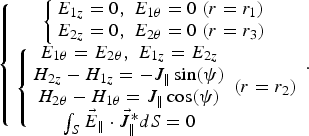
In Eq. (3), J 0 is the amplitude of the current density. In view of the different boundary conditions of the helical BPFL, two regions are divided to analyze the electromagnetic field distribution, such as Region I (r 1 < r < r 2) and Region II (r 2 < r < r 3). The permittivity and permeability of free space are ɛ0 and μ0, respectively. The filling dielectric is the same in Region I and Region II, and its relative permittivity and relative permeability are ɛr1 and μr1, respectively. The ideal metal boundary conditions and the uni-filar tape-helix boundary conditions are as
 $$\left\{\matrix{ \left\{\matrix{ E_{1z}=0\comma \; E_{1{\rm \theta} }=0\ \lpar r=r_1 \rpar \cr E_{2z}=0\comma \; E_{2{\rm \theta} }=0\ \lpar r=r_3 \rpar } \right. \cr \left\{\matrix{ E_{1{\rm \theta} }=E_{2{\rm \theta} }\comma \; E_{1z}=E_{2z} \cr H_{2z} - H_{1z}=- J_\parallel \sin \lpar {\rm \psi} \rpar \cr H_{2{\rm \theta} } - H_{1{\rm \theta} }=J_\parallel \cos \lpar {\rm \psi} \rpar \cr \int_S \vec{E} _\parallel \cdot \vec {J} _\parallel^{\ast} dS=0} \right. \lpar r=r_2 \rpar } \right. .$$
According to Eq. (4), the slow-wave electromagnetic field (E r, E θ, E z) and (H r, H θ, H z) can be obtained by solving Maxwell equations. Furthermore, the dispersion equation of the system can also be educed (Zhang, Liu, Feng, Reference Zhang, Liu and Feng2012; Zhang, Liu, Fan, et al., Reference Zhang, Liu, Wang, Fan, Zhang and Feng2011). In Section 2, analysis shows that the electromagnetic field shares the same form in the uni-filar and multi-filar tape helix situations. But the spatial harmonic numbers of the N-filar tape helix system should comply with the law in Table 2. In Figure 1a, the source current in each filar of tape helix flows in the same direction with the same velocity. In view of that, the “infinite long” system is symmetric and periodical, the amplitude and phase of the entire electromagnetic wave remains unchanged when the wave moves a displacement at p/N. Then, the probable spatial harmonic numbers of the N-filar tape-helix BPFL is as n =…, −Nn…−2N, −N, 0, N, 2N−Nn… So, the dispersion equation of the N-filar tape helix BPFL with continuous filling dielectric is as Eq. (5) (N = 3).
 $$\eqalign{& \sum\limits_{n=- \infty }^{+\infty } \lpar J_{\parallel n} J_{\parallel n}^{\ast }\rpar \left\{\matrix{\displaystyle{{ {\rm\gamma} _n [ \cos \lpar {\rm\psi} \rpar - {\rm\beta} _n n\sin \lpar {\rm\psi} \rpar /\lpar {\rm\gamma} _n^2 r_2 \rpar ] ^2 } \over { {\rm \omega} {\rm \varepsilon} _1 }}\cr \displaystyle{{\lpar I_{n2} K_{n1} - I_{n1} K_{n2} \rpar \lpar I_{n2} K_{n3} - I_{n3} K_{n2} \rpar } \over \matrix{\lpar I_{n2}^{\prime} K_{n3} - I_{n3} K_{n2}^{\prime} \rpar \lpar I_{n2} K_{n1}\cr - I_{n1} K_{n2} \rpar - \lpar I_{n2}^{\prime} K_{n1} - I_{n1} K_{n2}^{\prime} \rpar \cr \lpar I_{n2} K_{n3} - I_{n3} K_{n2} \rpar }} \cr+\displaystyle{{{\rm \omega}{\rm \mu} _1 \sin ^2 \lpar {\rm\psi} \rpar } \over {{\rm \gamma} _n }}\cr \displaystyle{{\lpar I_{n2}^{\prime} K_{n3}^{\prime} - I_{n3}^{\prime} K_{n2}^{\prime} \rpar \lpar I_{n2}^{\prime} K_{n1}^{\prime} - I_{n1}^{\prime} K_{n2}^{\prime} \rpar } \over \matrix{\lpar I_{n2} K_{n3}^{\prime} - I_{n3}^{\prime} K_{n2} \rpar \lpar I_{n2}^{\prime} K_{n1}^{\prime} - I_{n1}^{\prime} K_{n2}^{\prime} \rpar\cr - \lpar I_{n2} K_{n1}^{\prime} - I_{n1}^{\prime} K_{n2} \rpar \lpar I_{n2}^{\prime} K_{n3}^{\prime} - I_{n3}^{\prime} K_{n2}^{\prime} \rpar }} } \right\} \cr &\quad =0 \lpar n=- \infty\comma \; \ldots \comma \; - 3n\comma \; \ldots \comma \; - 6\comma \; - 3\comma \; 0\comma \; 3\comma \; \cr &\quad 6\comma \; \ldots 3n\comma \; \ldots \comma \; +\infty \rpar } .$$
In Eq. (5), γn is the phase constant of transverse direction in different regions. I n and K n are the modified Bessel functions of the first and second kind, respectively. I n1, I n2, and I n3 are the simplified forms of I n(γnr 1), I n(γnr 2), and I n(γnr 3), respectively, so do K n1, K n2, and K n3.  $I_{n2}^{\prime}$ represents the derivative of I n(γnr) to γnr when r = r 2, so do
 $K_{n2}^{\prime}$ and so on.
 $J_{\parallel n} J_{\parallel n}^{\ast}$ can be substituted by
 $\sin ^2 \lpar n{\rm \pi} {\rm \delta} /p\rpar /\lpar n{\rm \pi} {\rm \delta} /p\rpar ^2$ (Sensiper, Reference Sensiper1955). Define k i as the angular wave number (subscript i = 1, 2) that corresponds to the two divided regions in the BPFL.
 $k_i^2={\rm \omega} ^2 {\rm \varepsilon} _i {\rm \mu} _i\comma \; {\rm \gamma} _n^2={\rm \beta} _n^2 - k_i^2 $.
To the 3-filar tape helix BPFL (N = 3), the electromagnetic field only consists of spatial harmonics whose harmonic numbers are integer times to 3. In Eq. (5), the dispersion equation also only includes these harmonic terms, because other harmonics are effectively prohibited. The main work band of a helical BPFL (100 ns range) is at the low frequency band about dozens of MHz. Under this condition, the proportion of the basic harmonic component (0th) in the entire electromagnetic wave is much larger than the sum of other harmonics' proportions (Zhang, Liu, Wang, et al., Reference Zhang, Liu, Fan, Zhang, Wang and Feng2011; Zhang, Liu, Feng, Reference Zhang, Liu and Feng2012; Zhang, Liu, Fan, et al., Reference Zhang, Liu, Wang, Fan, Zhang and Feng2011). So, the dispersion characteristics of the multi-filar tape helix BPFL are mainly determined by the 0th harmonic component. By using of the approximation, we can easily solve Eq. (5) and the dispersion relation of the multi-filar tape-helix BPFL with continuous filling dielectric is as
 $$\left\{{\matrix{ {{\rm \omega} \lpar {\rm \gamma} _0 \rpar =\pm \displaystyle{{\cot \lpar {\rm \psi} \rpar } \over {\sqrt {{\rm \varepsilon} _1 {\rm \mu} _1 } }}\left\vert {{\rm \gamma} _0 } \right\vert T_0 \lpar {\rm \gamma} _0 \rpar ^{0.5}\comma \; T_0 \lpar {\rm \gamma} _0 \rpar \triangleq \displaystyle{{\lpar I_{{\rm 13}} K_{{\rm 11}} - I_{{\rm 11}} K_{{\rm 13}} \rpar } \over {\lpar I_{{\rm 03}} K_{{\rm 01}} - I_{{\rm 01}} K_{{\rm 03}} \rpar }}} \cr {{\rm \beta} _0 \lpar {\rm \gamma} _0 \rpar =\pm \left\vert {{\rm \gamma} _0 } \right\vert [ 1+\cot \lpar {\rm \psi} \rpar ^2 T_0 \lpar {\rm \gamma} _0 \rpar ] ^{0.5} } \cr } } \right. .$$
According to Eq. (6), the dispersion relation of the multi-filar tape-helix BPFL is the same as the dispersion relation of uni-filar tape-helix BPFL with continuous filling dielectric (Zhang, Liu, Fan, et al., Reference Zhang, Liu, Fan, Zhang, Wang and Feng2011). The phase velocity v ph and electric length τ0′ of the multi-filar helical BPFL with continuous filling dielectric are as
 $$v_{\,ph} \lpar {\rm \gamma} _0 \rpar ={\rm \omega} \lpar {\rm \gamma} _0 \rpar /{\rm \beta} _0 \lpar {\rm \gamma} _0 \rpar \comma \; {\rm \tau} _0^{\prime }=l_0 /v_{\,ph} \lpar {\rm \gamma} _0 \rpar .$$
Define the axial effective source current of the inner line and outer line of BPFL as I zin and I zout, respectively, and the corresponding characteristic impedances as Z in and Z out. φ is the scalar potential of the inner and outer line. I zin and I zout can be obtained by the integration of H θ in different regions, while φ is calculated by integration of E r in different regions. The characteristic impedances of the inner line and outer line of the multi-filar helical BPFL with continuous dielectric are as
 $$\left\{{\matrix{ Z_{in}=\displaystyle{{\rm \varphi} \over { - I_{zin} }}=\displaystyle{{\lpar I_{02} K_{01} - I_{01} K_{02} \rpar } \over {{\rm \beta} _0 M_{1in} K_{01} }}\comma \; \cr M_{1in}=\displaystyle{{2{\rm \pi} r_2 {\rm \omega} {\rm \varepsilon} } \over {{\rm \gamma} _0 }}\displaystyle{{I_{12} K_{01}+I_{01} K_{12} } \over {K_{01} }} \cr Z_{out}=\displaystyle{{\rm \varphi} \over {I_{zout} }}=\displaystyle{{\lpar I_{01} K_{02} - I_{02} K_{01} \rpar } \over {{\rm \beta} _0 M_{1out} K_{01} }}\comma \;\cr M_{1out}=\displaystyle{{2{\rm \pi} r_2 {\rm \omega} {\rm \varepsilon} } \over {{\rm \gamma} _0 }}\displaystyle{{\lpar I_{02} K_{01} - I_{01} K_{02} \rpar \lpar I_{12} K_{03}+I_{03} K_{12} \rpar } \over {K_{01} \lpar I_{02} K_{03} - I_{03} K_{02} \rpar }}} } \right. .$$
So the impedance of the BPFL is Z 0 = Z in + Z out. According to Eq. (8), the impedance matching condition of the inner line and outer line (Z in = Z out) with continuous filling dielectric can be obtained as
 $$\displaystyle{{I_{12} K_{01}+I_{01} K_{12} } \over {I_{02} K_{01} - I_{01} K_{02} }}=\displaystyle{{I_{12} K_{03}+I_{03} K_{12} } \over {I_{03} K_{02} - I_{02} K_{03} }}.$$
3.2. Impedance Matching Condition of Blumlein PFL with Discontinuous Filling Dielectrics
If the support insulator in Figure 1 is considered, the problem with discontinuous dielectrics is much more complicated. In view of the different boundary conditions of the helical BPFL, three regions are divided to analyze the electromagnetic fields distribution, such as Region I (r 1 < r < a), Region II (a < r < r 2) and Region III (r 2 < r < r 3). The effects of dielectric discontinuity on the dispersion relation, phase velocity, slow-wave coefficient, and electric length of the uni-filar tape-helix BPFL are analyzed (Zhang, Liu, Wang, et al., Reference Zhang, Liu, Wang, Fan, Zhang and Feng2011) in detail. In the situation of multi-filar tape-helix BPFL, the obtained dispersion relation of uni-filar tape-helix BPFL still works when the 0th harmonic dominates the dispersion characteristics in the low frequency band. According to paper (Zhang, Liu, Wang, et al., Reference Zhang, Liu, Fan, Zhang, Wang and Feng2011),
 $$\left\{\matrix{ {\rm \omega} \lpar {\rm \gamma} _0 \rpar =\pm \displaystyle{{\cot \lpar {\rm \psi} \rpar } \over {\sqrt {{\rm \varepsilon} _2 {\rm \mu} _2 } }}\left\vert {{\rm \gamma} _0 } \right\vert T_0 \lpar {\rm \gamma} _0 \rpar ^{0.5}\comma \;\cr {\rm \beta} _0 \lpar {\rm \gamma} _0 \rpar =\pm \left\vert {{\rm \gamma} _0 } \right\vert [ 1+\displaystyle{{{\rm \varepsilon} _i {\rm \mu} _i } \over {{\rm \varepsilon} _2 {\rm \mu} _2 }}\cot \lpar {\rm \psi} \rpar ^2 T_0 \lpar {\rm \gamma} _0 \rpar ] ^{0.5} \cr \matrix{ T_0 \lpar {\rm \gamma} _0 \rpar \triangleq \displaystyle{{\displaystyle{{I_{02}+a_{20} K_{02} } \over {I_{12} - a_{20} K_{12} }}+\displaystyle{{{\rm \mu} _2 } \over {{\rm \mu} _1 }}\displaystyle{{I_{13} K_{02}+I_{02} K_{13} } \over {I_{13} K_{12} - I_{12} K_{13} }}} \over {\displaystyle{{I_{12} - a_{10} K_{12} } \over {I_{02}+a_{10} K_{02} }} - \displaystyle{{{\rm \varepsilon} _1 } \over {{\rm \varepsilon} _2 }}\displaystyle{{\lpar I_{12} K_{03}+I_{03} K_{12} \rpar } \over {I_{02} K_{03} - I_{03} K_{02} }}}} \cr a_{10}=\displaystyle{{\displaystyle{{I_{0a} } \over {I_{0a} K_{01} - I_{01} K_{0a} }} - \displaystyle{{{\rm \varepsilon} _2 } \over {{\rm \varepsilon} _1 }}\displaystyle{{I_{1a} } \over {I_{1a} K_{01}+I_{01} K_{1a} }}} \over { - \displaystyle{{{\rm \varepsilon} _2 } \over {{\rm \varepsilon} _1 }}\displaystyle{{K_{1a} } \over {I_{1a} K_{01}+I_{01} K_{1a} }} - \displaystyle{{K_{0a} } \over {I_{0a} K_{01} - I_{01} K_{0a} }}}}\comma \;\cr a_{20}=- \displaystyle{{\displaystyle{{I_{0a} } \over {I_{0a} K_{11}+I_{11} K_{0a} }}+\displaystyle{{{\rm \mu} _2 } \over {{\rm \mu} _1 }}\displaystyle{{I_{1a} } \over {I_{11} K_{1a} - I_{1a} K_{11} }}} \over {\displaystyle{{{\rm \mu} _2 } \over {{\rm \mu} _1 }}\displaystyle{{K_{1a} } \over {I_{1a} K_{11} - I_{11} K_{1a} }}+\displaystyle{{K_{0a} } \over {I_{0a} K_{11}+I_{11} K_{0a} }}}} } } \right. .$$
In Eq. (10), a 10 and a 20 are two parameters only for abbreviation.  ${\rm \gamma} _0^2={\rm \beta} _0^2 \lpar {\rm \gamma} _0 \rpar - {\rm \omega} ^2 \lpar {\rm \gamma} _0 \rpar {\rm \varepsilon} _i {\rm \mu} _i$ (subscript i = 1, 2, 3, which respectively corresponds to the three divided regions in the BPFL). The phase velocity and electric length of the multi-filar tape-helix BPFL with discontinuous dielectrics are as
 $$\eqalign{&v_{\,ph} \lpar {\rm \gamma} _0 \rpar =\displaystyle{{{\rm \omega} \lpar {\rm \gamma} _0 \rpar } \over {{\rm \beta} _0 \lpar {\rm \gamma} _0 \rpar }}=\displaystyle{{\cot \lpar {\rm \psi} \rpar } \over {\sqrt {{\rm \varepsilon} _i {\rm \mu} _i } }}\sqrt {\displaystyle{g \over {T_0 \lpar {\rm \gamma} _0 \rpar }}+g^2 \cot \lpar {\rm \psi} \rpar ^2 }\comma \; \cr &\quad {\rm \tau} _0^{\prime}=l_0 /v_{\,ph0} \lpar {\rm \gamma} _0 \rpar .}$$
In Eq. (11), factor g = ɛiμi/ɛ2μ2. g = 1 and g ≠ 1, respectively, correspond to the continuous and discontinuous filling dielectric situation. The same way that educes the impedances in Eq. (8) can also be used to calculated the characteristic impedances of the inner line (r 1 < r < r 2) and the outer line (r 2 < r < r 3) of the multi-filar tape-helix BPFL with discontinuous dielectrics.
 $$\left\{{\matrix{ Z_{in}=\displaystyle{{\rm \varphi} \over { - I_{zin} }}=- \displaystyle{{\lpar I_{02}+a_{10} K_{02} \rpar } \over {{\rm \beta} _0 M_{2in} }}\comma \; \cr M_{2in}=\displaystyle{{2{\rm \pi} r_2 {\rm \omega} {\rm \varepsilon} _2 } \over {{\rm \gamma} _0 }}\lpar I_{12} - a_{10} K_{12} \rpar \cr Z_{out}=\displaystyle{{\rm \varphi} \over {I_{zout} }}=\displaystyle{{\lpar I_{02}+a_{10} K_{02} \rpar } \over {{\rm \beta} _0 M_{2out} }}\comma \;\cr M_{2out}=\displaystyle{{2{\rm \pi} r_2 {\rm \omega} {\rm \varepsilon} _1 } \over {{\rm \gamma} _0 }}\displaystyle{{\lpar I_{12} K_{03}+I_{03} K_{12} \rpar \lpar I_{02}+a_{10} K_{02} \rpar } \over {\lpar I_{02} K_{03} - I_{03} K_{02} \rpar }}} } \right. .$$
The impedance of the BPFL is Z 0 = Z in + Z out. According to Eq. (12), the impedance matching condition of the inner line and outer line (Z in = Z out) with discontinuous filling dielectric of the multi-filar tape-helix BPFL can be obtained as
 $$\displaystyle{{{\rm \varepsilon} _2 } \over {{\rm \varepsilon} _1 }}\displaystyle{{I_{12} - a_{10} K_{12} } \over {I_{02}+a_{10} K_{02} }}=\displaystyle{{I_{12} K_{03}+I_{03} K_{12} } \over {I_{03} K_{02} - I_{02} K_{03} }}.$$
4. EFFECTS OF DIELECTRIC DISCONTINUITY ON THE IMPEDANCE MATCHING CONDITION
First, we analyze the continuous filling dielectric situation (no support insulator) of the 3-filar tape-helix BPFL when de-ionized water is used as the dielectric (ɛr1 = 81.5 × μr1 = 1). The corresponding impedance matching condition is as Eq. (9). Define Y 1 and Y 2 as
 $$\eqalign{&Y_1 \triangleq \lpar I_{12} K_{03}+I_{03} K_{12} \rpar /\lpar I_{03} K_{02} - I_{02} K_{03} \rpar \comma \; \cr & Y_2 \triangleq \lpar I_{12} K_{01}+I_{01} K_{12} \rpar /\lpar I_{02} K_{01} - I_{01} K_{02} \rpar .}$$
Obviously, the impedance matching condition is only determined by the transverse phase constant γ0 and the radii of the tape-helix BPFL. If r 2 varies in the range from r 1 to r 3 while other parameters in Table 1 remain unchanged, curves of Y 1 and Y 2 are shown in Figure 2a according to different values of γ0. The fact that γ0 varies means that the frequency of the electromagnetic wave varies from Eq. (5). When γ0 increases from 1 to 5, the curve Y 1−r 2 and curve Y 2−r 2 of the same γ0 all have cross points with abscissa at r 2 = 0.1 m. This result corresponds to the previous impedance matching design in Table 1. Lewis et al. (Reference Lewis and Wells1959) has calculated the characteristic impedance of the helical BPFL by the non-dispersion “quasi-static” theory, and the impedance matching condition is r 3/r 2 = r 2/r 1. According to the geometric parameters in Table 1, r 2 = 0.1 m is also obtained from Lewis's theory. To the helical BPFL with continuous filling dielectric, the impedance matching condition in Eq. (9) is almost equivalent to r 3/r 2 = r 2/r 1 in Lewis's theory at the low frequency band.
(Color online) Characteristic impedance of the 3-filar tape-helix BPFL with homogeneous filling dielectric as de-ionized water (a) Impedance matching condition when r 2 varies (b) Z0 vs. γ0 of the spatial harmonics in the Blumlein PFL in discharge course.

According to Eq. (8) and the parameters in Table 1, characteristic impedance of the 3-filar tape-helix BPFL (Z 0), impedances of the inner line (Z in) and the outer line (Z out) are all shown in Figure 2b. To a helical BPFL at 100 ns range, the main work band is in the range about 0–10 MHz. So the effective range of γ0 is about γ0 < 10 from Eq. (6). In Figure 3b, the average values of Z in and Z out are 18.6 Ω and 17.5 Ω, respectively. It means that the impedances of the inner line and outer line basically match with each other. The characteristic impedance of the 3-fialr helical BPFL with continuous dielectric is about Z 0 = 36.1 Ω.
In the discontinuous filling dielectrics situation of the 3-filar helical BPFL, an air-core nylon support insulator (ɛr2 = 4.3 × μr2 = 1) is introduced in the system to support the tape helix. The parameters shown in Table 1 remains the same and the thickness of the nylon support is d = r 2−a = 6 mm. The filling dielectric is de-ionized water (ɛr1 = 81.5 × μr1 = 1). According to the impedance matching condition Eq. (13), define Y 3 and Y 4 as
 $$\eqalign{&Y_3 \triangleq \lpar I_{12} K_{03}+I_{03} K_{12} \rpar /\lpar I_{03} K_{02} - I_{02} K_{03} \rpar \semicolon \; \cr &Y_4 \triangleq {\rm \varepsilon} _2 \lpar I_{12} - a_{10} K_{12} \rpar /[ {\rm \varepsilon} _1 \lpar I_{02}+a_{10} K_{02} \rpar ]}.$$
If r 1 and r 3 remain unchanged but r 2 varies; the curves of Y 3 and Y 4 are shown in Figure 3a. When r 2 changes in the range from r 1 to r 3, the curve Y 3−r 2 and curve Y 4−r 2 under the same γ0 can not across each other. So, the conclusion is that impedance matching can not be realized by changing the radius of the 3-filar tape helix when the filling dielectric is discontinuous. In other words, although the thickness d of the nylon support is very small, the impedances of the BPFL still remain unmatched. From Eq. (12), the impedances of the 3-filar helical BPFL are calculated as shown in Figure 3b when γ0 < 10. The average values of Z in, Z out, and Z 0 are 53 Ω, 14.7 Ω, and 67.7 Ω in order. Z out in Figure 3b only has small changes in contrast to the Z out in Figure 2b. However, Z in in Figure 3b is just 2.85 times as the Z in in Figure 2b. The total impedance of the 3-filar helical BPFL also increases by 31.6 Ω due to the dielectric discontinuity. As a result, the impedances of the inner line and the outer line of the BPFL are completely unmatched.
(Color online) Characteristic impedance of the 3-filar tape helix BPFL with nylon support and filling dielectric as de-ionized water (a) Impedance matching condition when r 2 varies (b) Z0 vs. γ0 of the spatial harmonics in the Blumlein PFL in discharge course.

The impedance matching condition is very sensitive to the dielectric discontinuity. If the thickness d of nylon support varies while the other parameters in Table 1 remains unchanged, Z in and Z out are presented in Figure 4a and Figure 4b, respectively. In Figure 4a, the curves of Z in−γ0 almost have very small changes when γ0 changes and this result prove that the dispersion has very weak effect on Z in. However, when d increases form 0 to 0.5 mm × 1 mm × 3 mm × 6 mm and 10 mm, respectively, Z in increases form 18.6 Ω to 76.5 Ω. And when d increases by every 0.5 mm, Z in increases by 5.9 Ω on average. These data demonstrate that minor dielectric discontinuity can cause large changes of the characteristic impedance.
(Color online) Relations between Zin, Z0 and the thickness of nylon support (a) Zin vs. γ0 when d varies (b) Zout vs. γ0 when d varies.

Although the dielectric discontinuity only occurs in the region of the inner line as shown in Figure 1a, the filling dielectric in the region of the outer line is still continuous. However, Z out can not remain unchanged due to the coupling effect of electromagnetic field in the inner line and outer line. In Figure 4b, when d increases form 0 to 0.5 mm × 1 mm × 3 mm × 6 mm and 10 mm, respectively, Z out decreases form 17.6 Ω to 14 Ω in average. As the dielectric discontinuity in the inner line perturbs the coupling field of two lines of the BPFL, Z out decreases according to the dielectric discontinuity. This coupling effect of dielectric discontinuity on Z out can not be analyzed by other methods including Lewis's “quasi-static” theory.
In many real experiments, in order to avoid unwanted effects of the dispersion, “skin effect” and loss, thin tape helix (thickness <0.2 mm) is usually employed. As the thin tape is not strong enough to support itself, support for insulators must be used. In view of that filling dielectric, discontinuity can cause impedance mismatching of the multi-filar helical BPFL, support dielectric that has similar permittivity with the filling dielectric (ɛr2 ≈ ɛr1) should be employed. At last, castor oil (ɛr1 = 4.5) is used as filling dielectric to match with the nylon support (ɛr1 = 4.3) in experiments. If r 1 and r 3 remain unchanged but r 2 varies; the curves of Y 3 and Y 4 defined in Eq. (15) are plotted as shown in Figure 5a. Obviously, the curve Y 3−r 2 and curve Y 4−r 2 under the same γ0 get across with each other, and the abscissa of all the cross points is about r 2 = 0.1 m. The crossed curves basically correspond to the curves in Figure 2a. Results demonstrate that if ɛr2 ≈ ɛr1, the impedance matching condition Eq. (13) of discontinuous dielectrics is equivalent to Eq. (9). Characteristic impedances of the inner line and outer line of BPFL match with each other again. In Figure 5b, although the filling dielectric and the support dielectric are different, Z in ≈ Z out is still obtained. The average values of Z in, Z out and Z 0 are 80 Ω, 79 Ω, and 159 Ω as seen in Figure 5b.
(Color online) Characteristic impedance of the 3-filar tape helix BPFL with nylon support and filling dielectric as castor oil (a) Impedance matching condition when r 2 varies. (b) Z0 vs. γ0 of the spatial harmonics in the Blumlein PFL in discharge course.

5. PSPICE SIMULATION ANALYSIS AND EXPERIMENTS
In order to testify the impedance analysis of the 3-filar tape-helix BPFL based on dispersion theory, the 3-filar tape helix is produced as shown in Figure 6a. The thickness of the tape helix is about 0.02 mm. Three tapes in parallel curl around the air-core nylon support along the axial direction. At the two sides of the tape helix, two copper rings fix up the tapes respectively. Geometric parameters are all in line with Table 1. The pulse accelerator system including the 3-filar tape-helix BPFL is shown in Figure 6b and the equivalent structure of the accelerator system is presented in Figure 6c. The accelerator system consists of a primary charging capacitor with charging circuit, a trigger, a pulse transformer with closed core of iron-based amorphous alloy, a spark gap, tape-helix BPFL and a dummy load. The pulse transformer can boost the voltage up to 20–30 kV to charge the PFL.
(Color online) Pulse accelerator system and its structure in experiments (a) the inner shield and the 3-filar tape helix with nylon support (b) Photograph of the electron pulse accelerator (c) The structure of the accelerator in experiment.

The working principle of Figure 6c is as follows. First, the primary capacitor is charged by the charging circuit. Second, the trigger switches on just when the primary capacitor is charged to a certain level, and the primary capacitor discharges to the pulse transformer. Then, the pulse transformer boosts the voltage and charges the helical BPFL. When the BPFL is charged to the maximum voltage, the spark gap breaks down by itself. At last, the BPFL discharges fast to the dummy load and high-voltage pulse is formed on the load. The pulse duration of the formed voltage pulse is just twice as the electric length of the BPFL. Impedance matching among the inner line, the outer line, and the load of the BPFL has strong effect on the output voltage waveform. So, the quality of output electron beam of pulse accelerator is also confined to the impedance matching condition. By using the “traveling wave method” based on the telegraphers' equation, Cheng, Liu, Qian, et al. (Reference Cheng, Liu, Qian and Zhang2009) and Cheng, Liu, Zhang, et al. (Reference Cheng, Liu and Zhang2009) analyzed the effect of impedance mismatching between the helical BPFL (uni-filar tape helix and continuous dielectric) and the load on the output voltage waveform. However, not only the impedance mismatching between the BPFL and the load, but also the mismatching between the inner line and the outer line of the BPFL itself can cause bad output voltage waveforms. In this paper, the latter situation with dielectric discontinuity is analyzed in detail by dispersion theory.
In order to simulating the experimental system shown in Figure 6 and demonstrating the aforementioned dispersion analysis, Pspice codes are employed to directly analyze the effect of impedance matching of the 3-filar tape-helix BPFL with discontinuous dielectrics. The equivalent schematic of the experimental system is shown in Figure 7a. The 30 µF primary capacitor C 1 is charged to about 1 kV as the initial voltage. When t = 0, the switch is closed and C 1 starts to discharge to the circuit of the 1:37 pulse transformer. The characteristic parameters of the pulse transformer and the stray parameters (L k1, L k2, R 1 and R 2) of the transformer circuit are shown in Figure 7a. The spark gap is between the tape helix and the ground. L k3 is the sum of the spark inductance and the connective inductance, and L k3 is in parallel with the main gap. C d1 and C d2 are both capacitances of two capacitive voltage dividers, R D is the resistance of the resistive voltage divider, and L −gnd is the grounded inductance of the BPFL. The dummy load resistor is equivalent to the combination of three parts such as the ideal resistor R L, the parasitic inductor L R, and the parasitic capacitor C R. R L, L R, and C R can be measured by “HP-4285A” meter. T_mid_inner and T_mid_outer represent the inner line and outer line of the tape-helix BPFL, respectively. Z in, Z out, Z 0, and τ0′ are set completely according to the calculating results from Eqs. (7), (8), (11), and (12). In this paper, the central point is to analyze the effect of dielectric discontinuity on the impedance matching between the inner line and the outer line of the multi-filar tape-helix BPFL. So, the most interested situation is that R L = Z 0 = Z in + Z out, but Z in ≠ Z out. By measuring the voltage waveform at point A in Figure 7a, impedance matching can be analyzed.
(Color online) Pspice simulation circuit and results (a) The equivalent circuit of the accelerator system (b) Simulation results of load voltage pulse when de-ionized water was used as filling dielectric (c) Simulation results of load voltage pulse when castor oil was used as filling dielectric.

First, in the situation of continuous filling dielectric (without nylon support), de-ionized water (ɛr1 = 81.5) is used as filling dielectric. According to the calculating results from Eq. (7) and Figure 2b, parameters of the inner line (T_mid_inner) are set as Z in = 18.6 Ω, τ0′ = 274.1 ns; and the parameters of the outer line (T_mid_inner) are Z out = 17.5 Ω, τ0′ = 274.1 ns. R L = Z 0 = Z in + Z out = 36.1 Ω. The close time of the main gap is set as 20 ns and the self-breakdown voltage is about 24 kV. Other parameters are shown in Figure 7a. The output voltage waveform of the matched load in simulation is shown as Curve 1 in Figure 7b. The time when the load pulse appears corresponds to the breakdown time of the main gap. The pulse width at half maximum (PWHM) of the load voltage pulse is about 548 ns. The long tail of the load voltage pulse is basically flat only with small oscillations, which proves that the impedances of the inner line and the outer line of BPFL basically match with each other.
In the discontinuous filling dielectric situation, 6 mm-thickness nylon support (ɛr2 = 4.3) and de-ionized water (ɛr1 = 81.5) are considered simultaneously. According to the calculating results from Eq. (11) and Figure 3b, parameters of the inner line (T_mid_inner) are set as Z in = 53 Ω, τ0′ = 225.2 ns, and the parameters of the outer line (T_mid_inner) are Z out = 14.7 Ω, τ0′ = 225.2 ns. R L = Z 0 = Z in + Z out = 67.7 Ω, and other parameters in Figure 7a remain unchanged. The output voltage waveform of the matched load is shown as Curve 2 in Figure 7b. The PWHM of the load voltage pulse is about 450 ns that is far less than the PWHM of the continuous dielectric situation shown in Curve 1. The discontinuity of filling dielectric causes the “pulse shortening” phenomenon in the 3-filar tape-helix BPFL. In Curve 1, the pulse tail of the matched load is a large shoot with waveform similar to the main pulse. The average amplitude of the first reverse shoot is about 15.5 kV while the amplitude of the main pulse is about 22.5 kV. So, the shoot amplitude is about 68.8% of the main pulse amplitude. Obviously, although the impedance of the BPFL matches with the load (R L = Z 0), the load voltage pulse still has large reverse shoot in the pulse tail due to the impedance mismatching of Z in and Z out. The efficiency of pulse energy transferring decreases, attribute to the effect of dielectric discontinuity. Furthermore, if the load is vacuum diode, the electron beam bombards the cathode from the anode during the time of reverse pulse shoot, and damages of the diode can be caused.
In the situation when castor oil (ɛr1 = 4.5) is used to match with the 6 mm-thickness nylon support (ɛr2 = 4.3), parameters of the BPFL are also obtained from Eq. (11) and Figure 5b. Parameters of the inner line (T_mid_inner) are set as Z in = 80 Ω, τ0′ = 66 ns, and the parameters of the outer line (T_mid_inner) are Z out = 79 Ω, τ0′ = 66 ns. R L = Z 0 = Z in + Z out = 159 Ω, and the self-breakdown voltage of the main gap is set as 30 kV. Other parameters in Figure 7a still remain unchanged. The output voltage pulse of the matched load in simulation is shown in Figure 7c. The PWHM of pulse is about 132 ns and the pulse amplitude is 27.5 kV. The first reverse pulse caused by the impedance mismatching of the inner line and outer line is basically prohibited. The average amplitude of the first reverse pulse is about 3 kV, and it is only about 10.9% of the amplitude of the main pulse. The large shoots in the back tail of the pulse are mainly caused by the parasitic inductance and capacitance of the circuit. Simulation results demonstrate that impedances of the inner line and outer line of multi-filar helical BPFL basically match with each other when castor oil and nylon support are used.
Experiments are also carried out to demonstrate the theoretical analysis. The experimental system is shown in Figure 6 aforementioned. First, we test the 3-filar tape-helix BPFL with nylon support (d = 6 mm) and de-ionized water as filling dielectric. The parameters of the system are basically in line with Figure 7a. Initial charging voltage of the primary capacitor is about 1 kV, and the dummy load is adjusted to 68 Ω (measured at frequency of 2 MHz) to match with the characteristic impedance of the BPFL. The output voltage pulse of the matched load is shown in Figure 8a. The amplitude of main pulse is 19.5 kV and PWHM is about 450 ns. The amplitude of main pulse is a little smaller than the simulation result (22.5 kV) in Curve 2 of Figure 7b, due to the larger resistive loss in the real experimental system. The first reverse pulse is obvious with amplitude at 12 kV. Amplitude of the first reverse pulse is about 61.5% of the amplitude of main pulse, which basically corresponds to the simulation result 68.8% from Figure 7b.
(Color online) Output voltage pulse of the matched dummy load of the accelerator system in experiment (a) Output voltage pulse signal of the 68 Ω matched load when nylon support and de-ionized water was used (d = 6 mm) (b) Output voltage pulse signal of the 160 Ω matched load when nylon support and castor oil was used (d = 6 mm).

Change de-ionized water to castor oil as the filling dielectric in the BPFL while keeping the nylon support as the same, we carried out another experiment to test the impedance matching condition of the 3-filar tape-helix BPFL. Of course, the distance between the main spark gap is adjusted to a longer level, and other conditions shown in Figure 7a remain unchanged. The dummy load is adjusted to 160 Ω (measured at frequency of 10 MHz) to match with the characteristic impedance of the BPFL. The output voltage pulse of the matched load is shown in Figure 8b, with amplitude and PWHM of the main pulse at 24 kV and 126 ns, respectively. The first reverse pulse is prohibited effectively with amplitude only at 3 kV (12.5% of the main pulse amplitude). The experimental output voltage waveform of the matched load in Figure 8b basically corresponds to the waveform of simulation in Figure 7c. Experimental result in Figure 8b shows that the impedances of the inner line and outer line match with each other.
The fact that Experimental results basically correspond to circuit simulation results demonstrate that the Pspice circuit simulation is basically correct and reliable. The important parameters of the BPFL set in simulations are just from the calculation form electromagnetic dispersion theory. So, the conclusion is that the dispersion analysis on the impedance matching of the inner line and outer line of the multi-filar tape-helix BPFL with discontinuous filling dielectric is correct.
5. CONCLUSIONS
In this paper, the impedance matching relations of the inner line and outer line of the 3-filar tape-helix BPFL are analyzed based on electromagnetic dispersion theory. In the “infinite long” multi-filar tape-helix BPFL, the probable existed spatial harmonic numbers are a set of discontinuous integers and the 0th harmonic component still dominates the dispersion characteristics of the multi-filar BPFL in the low frequency band. The effects of discontinuous filling dielectrics on the characteristic impedance and impedance matching condition are analyzed in detail in contrast to the continuous filling dielectric situation of multi-filar BPFL. When de-ionized water is used as the filling dielectric and the thickness of nylon support of the 3-filar tape helix is 6mm, the characteristic impedances of the inner line and outer line are obtained as 53 Ω and 14.7 Ω in experiment. However, when castor oil with permittivity getting close to the permittivity of nylon is used to substitute de-ionized water as filling dielectric, impedances of the inner line and outer line are obtained as 80 Ω and 79 Ω in experiment. Impedance mismatching problem of two lines of the BPFL is solved. The fact that Circuit simulation and experimental results basically correspond to the results of dispersion theory, demonstrates that the dispersion theory and analysis on impedance in this paper are correct. The conclusions are helpful in accurate design and waveform reformation of complicated helical BPFL.
ACKNOWLEDGMENTS
This work was supported by the National Science Foundation of China under Grant No.51177167. It's also supported by the Fund of Innovation, Graduate School of National University of Defense Technology under Grant No.B100702.



