I. INTRODUCTION
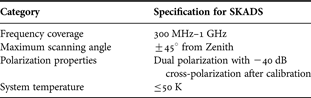
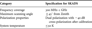
Wide–band dual-polarized aperture arrays with electronic scanning are increasingly required for various applications. Many system descriptions have well-defined requirements for range of scan angles, a polarization, and bandwidth. Generally, wide range of scans and low cross–polarization are desired across the wide operational bandwidth. For square kilometer array (SKA) radio telescope, the target specification assumed in this paper for the mid-frequency dense aperture array design study is summarized in Table 1.
Specification for the SKADS mid-frequency range dense aperture array.
The stripline-fed Vivaldi tapered slot antenna (TSA) is widely used for its potential in wide–band and wide scan performance [Reference Chio and Schaubert1]. Recent realizations include the THousand Element Array (THEA) [Reference Kant, Kokkeler, Smolders and Gunst2] and Electronic Multi-Beam Radio Astronomy ConcEpt (EMBRACE) [Reference Ruiter and van der Wal3] developed by ASTRON.Footnote 1 However, these arrays are only single polarized, the cross-polarization properties of such antennas over the wide scan volume need more investigations [Reference Schaubert4]. In order to reduce the cost, a recent development has included a single slotline implementation by printing copper on one side of the thin foil of polyester to replace tri-plate approaches. A differential line is used to feed the TSA slotline. It can then be directly connected to a differential input low–noise amplifier (LNA). This design is named Foilbased LOW cost PAcman Differential Dual–polarized Demonstrator (FLOWPAD3) [Reference Arts, Maaskant, de Lera Acedo and bij de Vaate5].
A “bunny-ear” design has been reported in [Reference Lee, Livingston and Koenig6]. It demonstrates improvements including a lower cross-polarization compared to a Vivaldi approach. To retain the impedance matching and the cross-polarization performance over a broad bandwidth and wide scan angle, the corrugated comblines along the edges of the conducting plates between the dense “bunny-ear” elements have been introduced. Such a design is named as bunny ear combline antenna (BECA) [Reference Zhang and Brown7]. A BECA is designed to operate over the mid-frequency range (e.g. between 300 MHz and 1 GHz) for square kilometer array design study (SKADS).
Munk dipole antennas use a fundamentally different approach to design the wide–band array [Reference Munk8, Reference Munk9], which has potential low production costs by using a planar structure. In this mutual coupling is intentionally utilized between the dipole elements, and controlled by introduction of capacitance. The increased capacitance between the ends of dipoles distributes smooth fields for a broader bandwidth. Elements with other shapes have been used to optimize performances for applications such as SKA. In particular, antenna elements formed by octagonal rings produce improved performance over elements of other polygonal shapes. In addition, a meta-material layer comprising printed rings has been placed over the array to further enhance the scan performance. This replaces layers of dielectric slabs, which have been suggested for a recent–developed current sheet array [Reference Munk10]. The resulting structure is termed as the octagonal ring antenna (ORA) [Reference Zhang and Brown11].
In this paper, three different wide-band array structures are compared by studies of finite-arrays using the different element approaches. They were designed and measured over a frequency range of 300 MHz – 1 GHz, which is compatible with a potential use for SKA applications. This paper is organized as follows. In Section II, three antenna prototypes for SKADS are introduced. Section III describes the fabricated finite-arrays for performance investigation. The cross-polarization performance is analyzed in Section IV, while Section V reports the radiation patterns based on the finite-array analysis. Section VI concludes the paper.
II. APERTURE ARRAY ANTENNA ELEMENTS
Three antenna element prototypes have been developed and measured. In order to understand the characteristics of the antenna elements in the large arrays, finite-arrays have been fabricated and their performances are compared.
A) FLOTT antenna
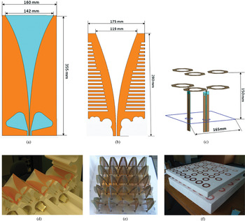
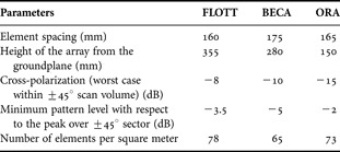
FLOTT is a Vivaldi antenna based on the FLOWPAD3 approach, and it stands for FLOWPAD3 Towards Two-polarization array demonstrator (FLOTT) [Reference Arts, Maaskant, de Lera Acedo and bij de Vaate5]. In this antenna, the transformer for a standard Vivaldi antenna is removed and the single tapered slot is fed directly through a differential line. The fabricated FLOTT is shown in Fig. 1(d). The depth of the element from the groundplane is 355 mm as indicated in Fig. 1(a).
The aperture array antenna prototypes for SKADS: (a) FLOTT; (b) BECA; (c) ORA; (d) FLOTT mini array; (e) BECA mini array; and (f) ORA mini array.

B) BECA
The bunny ear antenna can produce a better cross-polarization performance by tapering the outer edge of the conducting plate at the back end, and as a result, the element depth can be significantly shorter compared to conventional Vivaldi antennas. The shorter element depth of the bunny ear design (e.g. less than one wavelength at the high end of the operational frequency band) reduces the possibility of producing complex propagation modes along the tapered plate. Smoother impedance variations with scan angle is observed by corrugating the conducting flares of the bunny-ear antennas along their outer edge. A sub-panel of the finite BECA array is shown in Fig. 1(e). The element height from the groundplane is 280 mm, and the single BECA element is shown in Fig. 1(b).
C) ORA
As shown in [Reference Zhang and Brown11], an ORA array has demonstrated unique characteristics with its two-layered planar architecture. The overall height of the array can be considerably reduced compared with other two FLOTT or BECA arrays, it is 150 mm for the ORA. A fabricated small–scale ORA is shown in Fig. 1(f). The single ORA element together with the coplanar waveguide feed is indicated in Fig. 1(c).
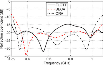
Three prototype array antennas have been optimized to meet the specifications mentioned in Table 1. Periodic boundaries have been applied for a single unit cell, which consists of two dual–polarized elements. The simulated active reflection coefficient for the element in an infinite array is given in Fig. 2. The active reflection coefficient has been defined in [Reference Kant, Patel, Wijnholds, Ruiter and van der Wal12], and the Computer Simulation Technology (CST) Microwave Studio [13] has been used for the simulations. All the simulated results reported in this paper are based on the CST Microwave Studio.
The active reflection coefficient for elements in an infinite array.

III. Finite antenna arrays
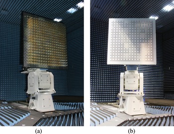
In practice, such antenna arrays are not infinite in size. In order that a single element behaves as if it were in a large array the element must be immersed in an array. Preliminary investigations indicate that the size of the array is required to be greater than two–and–a–half–wavelength at the lowest frequency to reduce the edge effect to an acceptable level. A 16 × 16 × 2 dual–polarized BECA array was built and shown in Fig. 3(a). The element separation is 175 mm and the resulting aperture of the array is 2800 mm. The height of the BECA element is 280 mm, less than one wavelength at the highest frequency and significantly shorter than typical tapered slot type of antennas. In contrast, the FLOTTFootnote 2 design of a Vivaldi array has an element height of 355 mm. The tapered slotline of the FLOTT antenna has been fed directly without the coupling mechanism between the stripline and the slotline for a conventional Vivaldi. A 16 × 16 × 2 FLOTT finite-array has been built with the element separation of 160 mm and the array aperture of 2560 mm.
The finite-arrays with 16 × 16 dual-polarized elements: (a) BECA; (b) ORA. (Photo courtesy SELEX Galileo.)

In addition to the two different types of tapered slotline antennas including FLOTT and BECA, a 16 × 16 × 2 finite ORA was built and it is shown in Fig. 3(b). The element spacing is 165 mm and the capacitance value for the bulk capacitors between the elements is 1 pF. Three-arrays have been measured in a compact antenna test range. The scanned array element patterns in the finite-arrays are investigated in the following sections.
IV. Cross-polarization
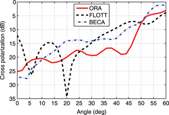
The measured cross-polarization in the D-plane at 1 GHz for the center element of the three finite-arrays is shown in Fig. 4. The D-plane is the intercardinal plane at the 45° cut, while the E-plane and H-plane refer to 0 and 90° cuts, respectively [Reference Ludwig14]. The comparison shows that the element in the center of finite ORA array produces a lower and stable cross-polarization than that of the other two elements in the center of the finite FLOTT and BECA arrays. It is indicated that the cross-polarization is less than −15 dB for the ORA array and slightly more than −10 dB for the tapered slot structures within the 45° scan volume.
The cross-polarization comparison in the D-plane at 1 GHz for the center element in the 16 × 16 dual polarized FLOTT, BECA, and ORA arrays.

V. Radiation pattern analysis
The immersed element pattern is in general different from the radiation pattern for an isolated element due to the mutual coupling in the high-density antenna array. These three antenna prototypes are balanced structures and a balanced feed is required. Baluns have been designed to provide the transition between the unbalanced driven system and the balanced coplanar stripline (CPS) connected to the feed terminals on the balanced antennas. The balun designs are based on the guidelines given in [Reference Thaysen, Jakobsen and Appel-Hansen15].
The immersed element pattern at three frequencies for the center element of the three finite-arrays have been measured and is shown in Fig. 5. These measurements have been conducted in the presence of CPS-coplanar waveguide (CPW) transition baluns and their effects are included. We note that the same balun was used for the BECA and FLOTT. Any possible radiation from the balun has similar impact on the measured patterns, hence allowing a direct comparison. The summary of the comparison for the three prototypes is given in Table 2.
The immersed element pattern of the 16 × 16 finite-arrays, FLOTT, BECA, and ORA, (a) E-plane and (b) H-plane.

Performance summary for the three-array prototypes based on finite-array studies.

All three antennas demonstrate a broad band impedance characteristic. At lower frequencies the radiation patterns of all three antennas are wide, which is required for wide angle scanning; however, the high-frequency measurements indicate that the FLOTT design has a substantial narrow beamwidth in the E-plane and a similar characteristic in the H-plane at 1 GHz. The beamwidth in both planes for the FLOTT antenna becomes broader for lower frequencies. The measured beamwidth for the FLOTT antenna at 700 MHz is also shown in Fig. 5.
The 8 × 8 finite sub-arrays have been scanned with a directly mounted analog beam forming network. The measured and simulated results for the ORA sub-array at 1 GHz are shown in Fig. 6. Good agreement is observed. The scanned sub-array patterns for the BECA and ORA at other frequencies are shown in Fig. 7. It also indicates that the cross-polarization performance for ORA has less variation with frequencies when the array is being scanned.
The measured scanned array pattern for the 8 × 8 ORA sub-array compared with the simulated result.

The scanned array pattern of the 8 × 8 finite-arrays with a directly mounted analog beam-forming network: (a) BECA sub-array and (b) ORA sub-array.

The pattern measurements for these antennas are based on the CPS-CPW baluns. However, this type of balun can be lossy. This can be problematic for particular applications such as astronomy. The ORA elements can also be fed through two coaxial cables, leading to a very low loss. This is shown in Fig. 8(a). The gain for ORA element with the coaxial feeding cables is given in Fig. 8(b).
The alternative feeding method for ORA: (a) ORA with differential feed and (b) the gain of the ORA element in an infinite array.

VI. Conclusions
The paper investigates the element design for wide-band dense aperture arrays. Three finite-array prototypes have been fabricated and measured in the same compact range. The prototypes consist of the conventional three-dimensional tapered slotline Vivaldi antenna, bunny-ear slotline design but with comblines and the newly developed octagon ring antenna of a two-dimensional planar structure. The array with a planar structure shows an overall better performance including broader element patterns and lower cross-polarization in addition to easy fabrication. The ORA array may operate over 4:1 bandwidth and better than −15 dB cross-polarization within a ±45° scan volume. These elements are initially designed for the radio astronomy application operating from 300 MHz to 1 GHz. However, they are readily scalable to other frequency ranges for various applications.
ACKNOWLEDGEMENTS
This effort/activity is supported by the European Community Framework Programme 6, square kilometer array design studies (SKADS), contract no. 011938.
 Yongwei Zhang received his B.Sc. degree in communication engineering from Jilin University, Changchun, P. R. China, in 1996, and Ph.D. degree in electrical and electronic engineering from the University of Manchester in 2007. In 1996, he joined Lucent Technologies, where he worked as a system engineer on 5ESS and PHS (Personal Handy-phone System) systems. In 1998, he worked at Bell Labs, Naperville, USA, on communication system engineering tools development. In his career atLucent Technologies from 1996 to 2003, he had been involved in personal-handy-phone system network design and optimization. He had experience on adaptive array antenna design (TDMA/FDMA) and optimization for PHS system. He joined the University of Manchester from 2003 in the Microwave and Communication Systems research group. His current research interests are mainly concerned with UWB communication system engineering including channel modeling, system performance analysis, UWB antenna design and Square Kilometer Array (SKA) antenna design.
 Anthony K. Brown joined the University of Manchester in May 2003 as head of the Microwave and Communication Systems research group. Professor Brown has had over 30 years of experience in research and development in relation to microwave antennas, communications and radar systems. Starting work at GEC-Marconi Research Laboratories (1974) he worked on early satellite communications satellites including the 19 m beam waveguide Goonhilly IV ground station. After a period with STL (Harlow) working on a variety of topics including adaptive and microstrip antennas, he was the first Racal Research Fellow on Telecommunications at University of Surrey in 1980. He joined Racal full time in 1983, mainly working on military communications. He has been involved in cellular radio from the initial deployment in the UK and extensively in mobile satellite communications. In 1987, Professor Brown founded Easat, a successful civilian radar supplier, where he remains as Chairman. Professor Brown was a founding member of the EPSRC Communications College. He is a Senior Member of the IEEE, a Fellow of the IEE and of the Institute of Mathematics and its Applications (IMA). He is a UK representative to the European Union COST ASSIST initiative, a recent past member of the FCC Technical Advisory Commission (TAC) and is a past Chairman of the UK Chapter of the Applied Computational Electromagnetics Society (ACES). Professor Brown lectures in communication systems and in radar. His current research interests include ultra–wide–band antennas and propagation, large–scale CEM, radio astronomy instrumentation, cross-system interference issues, secure high-frequency networks and intelligent antennas.