1 Introduction and overview
Magnetic fields with tailored spatial profiles are important in many areas. Examples include medical imaging (Westbrook Reference Westbrook2014), plasma and fusion research (National Academies of Sciences, Engineering, and Medicine 2021) and the confinement of antimatter (Fajans & Surko Reference Fajans and Surko2020). Regarding the latter, positrons have proven useful for scientific and technological applications ranging from fundamental atomic physics to materials characterization (Schultz & Lynn Reference Schultz and Lynn1988; Wahl & Buchanon Reference Wahl and Buchanon2002; Gidley et al. Reference Gidley, Chi, Wang and Vallery2006; Charlton & van der Werf Reference Charlton and van der Werf2015; Cassidy Reference Cassidy2018; Fajans & Surko Reference Fajans and Surko2020). However, sources of positrons provide relatively small particle fluxes as compared with, for example, their electron antiparticle counterpart; and this has severely limited their utility.
One unfulfilled technical capability is a practical device to accumulate and store large numbers of positrons (e.g. ${>}10^{10}$ ) for many minutes or longer. This paper discusses considerations relevant to tailoring a magnetic field for such a device. An immediate need for a high-capacity positron trap is to provide bursts of positrons to create a magnetically confined electron–positron (‘pair’) plasma (Pedersen et al. Reference Pedersen, Danielson, Hugenschmidt, Marx, Sarasola, Schauer, Schweikhard, Surko and Winkler2012; Stoneking et al. Reference Stoneking, Pedersen, Helander, Chen, Hergenhahn, Stenson, Fikse, Linden, Saitoh and Surko2020). Such a plasma is expected to have unique properties. For example, it will be useful for fundamental plasma physics studies and relevant in astrophysical settings (Stoneking et al. Reference Stoneking, Pedersen, Helander, Chen, Hergenhahn, Stenson, Fikse, Linden, Saitoh and Surko2020; Goodbread & Liu Reference Goodbread and Liu2022).
The most common confinement device for positrons is the Penning–Malmberg (PM) trap (Malmberg & Driscoll Reference Malmberg and Driscoll1980; Driscoll, Fine & Malmberg Reference Driscoll, Fine and Malmberg1986; Murphy & Surko Reference Murphy and Surko1992; Danielson et al. Reference Danielson, Dubin, Greaves and Surko2015; Fajans & Surko Reference Fajans and Surko2020). It consists of a set of cylindrical electrodes arranged axially in a uniform magnetic field. The magnetic field provides radial confinement, while axial confinement of the single sign of charge is achieved by electrostatic potentials on the end electrodes. However, as the trap is filled, the plasma space charge increases. Confinement in PM traps, while good, is not perfect. The radial particle excursions in the strong space-charge electric fields lead to plasma heating and enhanced outward diffusion of the particles across the magnetic field (Malmberg & Driscoll Reference Malmberg and Driscoll1980; Danielson & Surko Reference Danielson and Surko2006a).
Currently, confinement of over $10^9$ positrons has been achieved in a single PM trap (Jorgensen et al. Reference Jorgensen, Amoretti, Bonomi, Bowe, Canali, Carraro, Cesar, Charlton, Doser and Fontana2005; Fitzakerley et al. Reference Fitzakerley, George, Hessels, Skinner, Storry, Weel, Gabrielse, Hamley, Jones, Marable, Tardiff, Grzonka, Oelert and Zielinski2016; Blumer et al. Reference Blumer, Charlton, Chung, Cladé, Comini, Crivelli, Dalkarov, Debu, Dodd and Douillet2022). This was done by trapping positrons using a buffer-gas trap and then stacking pulses in an ultrahigh-vacuum trap in a large magnetic field where the particles cool by cyclotron radiation. The number of trapped positrons $N$
 increases linearly with the number of pulses, and stacking can be done with near-unity efficiency.
However, as the number of confined positrons $N$ is increased, the required confinement voltage (which scales as $N/L$
 , with $L$
 the plasma length) and the radial space-charge electric field increase. This leads to unacceptable levels of positron heating and positronium formation, where the latter is a virulent positron loss process, even in an otherwise good vacuum. Thus, the increasingly large voltages required on the end electrodes limit the maximum particle capacity of a single PM trap to ${\sim }10^{10}$
 particles, which has been achieved for electrons (Danielson, Weber & Surko Reference Danielson, Weber and Surko2006b). Other confinement considerations limit $L$
 in typical traps to from one tenth to a few tenths of a metre (Danielson et al. Reference Danielson, Weber and Surko2006b; Hurst et al. Reference Hurst, Danielson, Baker and Surko2019).
Danielson et al. (Reference Danielson, Dubin, Greaves and Surko2015) and Fajans & Surko (Reference Fajans and Surko2020) describe the many factors that can affect the confinement of single-component plasmas in PM traps. Unfortunately, there are no quantitative predictions for the confinement of single-component plasmas in the practical PM traps used in actual experiments, and so the available guidance is empirical. While electrostatically trapped particles can also contribute to a lack of confinement (Notte & Fajans Reference Notte and Fajans1994; Kabantsev & Driscoll Reference Kabantsev and Driscoll2002), this effect, which appears as if it can possibly be mitigated by use of a multi-ring electrode structure (Mohamed, Mohri & Yamazaki Reference Mohamed, Mohri and Yamazaki2013) and colloidal-graphite-coated electrodes (Fajans & Surko Reference Fajans and Surko2020), is not considered further here.
To circumvent the space-charge constraints on $N$ , it has been proposed to achieve the required accumulation and storage of large numbers of positrons in a so-called ‘multi-cell trap’ (MCT) (Surko & Greaves Reference Surko and Greaves2003; Danielson & Surko Reference Danielson and Surko2006a) by arranging many PM traps (i.e. ‘cells’) in series, and lines of these cells in parallel, in a common vacuum system and immersed in the uniform field provided by a solenoidal superconducting magnet. The benefit of this MCT design is supported by a variety of experimental and theoretical work (Malmberg & Driscoll Reference Malmberg and Driscoll1980; Malmberg et al. Reference Malmberg, Driscoll, Beck, Eggleston, Fajans, Fine, Huang and Hyatt1988; Danielson & Surko Reference Danielson and Surko2006a; Danielson et al. Reference Danielson, Dubin, Greaves and Surko2015; Fajans & Surko Reference Fajans and Surko2020). Various aspects of the technology required for an MCT for positrons have now been developed, including high-efficiency, off-axis transfer and good off-axis confinement, and further work is in progress (Danielson et al. Reference Danielson, Weber and Surko2006b; Danielson, Hurst & Surko Reference Danielson, Hurst and Surko2013; Baker et al. Reference Baker, Danielson, Hurst and Surko2015; Hurst et al. Reference Hurst, Danielson, Baker and Surko2019; Singer et al. Reference Singer, Konig, Stoneking, Steinbrunner, Danielson, Schweikhard and Pedersen2021, Reference Singer, Danielson, König, Sunn Pedersen, Schweikhard and Stenson2023).
Presented here is a discussion of the design considerations for the magnetic field for such an MCT. They are intended to optimize the alignment of the field with respect to the electrode axes and to avoid magnetically trapped particles, both of which are believed to lead to better particle confinement and hence improved positron storage capabilities (Danielson et al. Reference Danielson, Dubin, Greaves and Surko2015). Also presented here are the results of a complementary experimental study of confinement as a function of magnetic field alignment in a PM trap, and these results are related to the magnetic field design study.
2 Electrode structure for a MCT
A current MCT design calls for PM cells $100$ to $300$
 mm long and arrangements of one or a few concentric rings of these cells (Baker et al. Reference Baker, Danielson, Hurst and Surko2015; Hurst et al. Reference Hurst, Danielson, Baker and Surko2019). The magnetic field $B_0=5$
 T is chosen to provide the required cyclotron cooling (cooling rate $\propto B^2$
 ), since adequate cooling is critical to the required long confinement times (Hurst et al. Reference Hurst, Danielson, Baker and Surko2019; Fajans & Surko Reference Fajans and Surko2020). Two possible versions of such a trap to confine positron numbers $N \ge 10^{10}$
 are illustrated in figure 1: Design (i) is a 21-cell trap consisting of three banks of seven storage cells (SC); and Design (ii) is a 19-cell trap with one bank of two concentric rings of SC arranged around a centre cell. In both designs, the first ring of cells is approximately $25$
 mm off axis; and in (ii), the second ring of cells is $50$
 mm off axis.
Two possible electrode structures for a multi-cell positron trap with a capacity of $N\ge 10^{10}$ particles. (a) Design (i): three in-line banks of seven SC. (b) Design (ii): one bank of 19 SC. Both have a MC which takes bursts of positrons from a separate positron trap and deposits them in the on- and off-axis SC.

A ‘master cell’ (MC) is placed at the end of each arrangement of SC. It is used to move plasmas, accumulated in a separate positron trap, off-axis to fill the SC using autoresonant excitation of the diocotron mode (Fajans, Gilson & Friedland Reference Fajans, Gilson and Friedland1999; Danielson et al. Reference Danielson, Weber and Surko2006b; Baker et al. Reference Baker, Danielson, Hurst and Surko2015; Hurst et al. Reference Hurst, Danielson, Baker and Surko2019). Either electrode arrangement would occupy a total volume of one to a few litres of the vacuum system for a trap for $N \geq 10^{10}$ positrons. Ideally, one would like the magnetic field in this volume to be uniform to a high degree of accuracy and uniformly aligned with the axes of the confinement electrodes, since such field errors in PM cells are known to degrade plasma confinement and complicate off-axis injection (Baker et al. Reference Baker, Danielson, Hurst and Surko2015).
3 Magnetic field considerations
There are interrelated requirements for the confining magnetic field for a practical MCT for positrons. One would like to avoid magnetically trapped particles, which are predicted to lead to poor particle confinement (Fajans Reference Fajans2003; Eggleston et al. Reference Eggleston, McMurtry, Kabantsev and Driscoll2006). This can occur if there is a maximum in the magnetic field (i.e. a ‘magnetic mirror’) in the trapping region. This effectively divides the particles into two separate populations, trapped and untrapped, by a separatrix in velocity space. This, in turn, results in increased transport and poor confinement. This can be prevented by arranging the field $B(z)$ to be slightly non-uniform with no maximum (i.e. no ‘magnetic mirror’) in the confinement region of the trap, where $z$
 is oriented in the direction of the axis of symmetry. Assuming the magnetic field is symmetric about $z = 0$
 , $r = 0$
 , this requirement is the constraint

within the confinement region.
However, the fact that $\partial B_{z}(z)/\partial z$ is non-zero and that many plasmas are in cells off the magnetic axis leads to a significant radial component of $B$
 off-axis as determined by the solution to $\boldsymbol {\nabla }\boldsymbol {\cdot }\boldsymbol {B} = 0$
 . Assuming cylindrical symmetry, the radial component of $B$
 will be

Such non-zero values of $B_r$ result in the bending of the off-axis magnetic field lines. While the effects of magnetic field alignment on PM trap confinement have been discussed for straight field lines misaligned with respect to the electrode axis (see Fine Reference Fine1988, § 6.3; Hart Reference Hart1991; Mitchell Reference Mitchell1993, § 3.4), to our knowledge, the effects of continuously bent field lines, such as those described here, on transport have not been considered previously. This is potentially important for the MCT, since good confinement is required for a high-capacity trap. Note that the field non-uniformities considered here are radial, as opposed to the azimuthal (i.e. magnetic multipole) asymmetries which have been discussed previously (Fajans et al. Reference Fajans, Bertsche, Burke, Chapman and van der Werf2005; Fajans, Madsen & Robicheaux Reference Fajans, Madsen and Robicheaux2008).
Assuming $B_z \approx B_0$ , which is easily fulfilled for the situations considered here, and writing $\textrm {d} r \approx \theta \,\textrm{d} z$
 , where $\theta \approx B_r/B_0\ \ll 1$
 is the angle of the field line with respect to the $z$
 axis, the radial deviation of the field line at axial position $z$
 from that at $z = 0$
 will be

where $r(0)$ is the centre of a SC. The root-mean-square deviation

of the field line from its average position $\bar {r}$ over an interval from $z = 0$
 to $d$
 is a measure of its straightness. Field alignment is often discussed for a straight field line oriented at angle $\theta$
 to the $z$
 axis. In this case the correspondence is

As discussed above and illustrated in figure 1, a trap with approximately 20 cells could be: Design (i) configured with three banks of seven cells displaced axially for 21 cells (figure 1(a)), or Design (ii) with one bank of 19 cells of the same length, with one centre cell plus a ring of six and a second ring of 12 SC (figure 1(b)). There are several considerations as to which design is best. The electrodes in (i) are easier to connect to voltage sources, while (ii) affords better pumping, which is of great importance for large values of space charge (Hurst et al. Reference Hurst, Danielson, Baker and Surko2019).
The constraint of (3.1) would require a longer region of ${\partial B_r}/{ \partial z} \neq 0$ for Design (i), leading to increased field-line bending as per (3.2) and (3.3). Since avoiding magnetically trapped particles is assumed to be important, Design (ii) is preferred over Design (i). Thus Design (ii) (cf. figure 1(b)), with 19 cells, is chosen for further study. However, Design (i) does have distinct advantages: it avoids having to move, and position, plasmas farther off axis and wiring concentric rings of electrodes, one inside the other. At this early stage of MCT development, it is unclear which design will prove best; and so Design (i), while not considered further here, is still considered to be a good candidate.
In the following, we assume SC electrodes with $12$ mm inner diameter and $2$
 mm thick walls separated radially by a minimum distance of $6$
 mm. Thus the centre of the first ring of six electrodes is at $r = 22$
 mm, the second ring of 12 electrodes is at $r = 44$
 mm and the confinement volume of this second ring of SC extends to $r = 50$
 mm.
4 Magnet design
Considered here are possible magnetic field coil configurations for the Design (ii) MCT. The outer diameter of the electrode structure, the accompanying vacuum vessel and additional space in the cryostat for thermal insulation to allow for superconducting operation put a lower limit on the inner radius of the solenoid, which is assumed here to be $R = 130$ mm. The extent of the tailored magnetic field region is determined by the combined length of the MC and SC (assumed total length of $500$
 mm, as shown in figure 1) and the outermost extent of the confinement volume of the furthest off-axis cell $(r = 50$
 mm). This volume, with $r \leq 50$
 mm and $z \leq \pm ~250$
 mm, is referred to as the ‘confinement region’ in which the goal is to produce a magnetic field configuration that optimizes confinement.
Magnetic field computations were done using COMSOL Multiphysics, version 5.6, using a two-dimensional axisymmetric model with the static magnetic fields interface. The magnetic coils described below are assumed to be homogeneous, multi-turn coils using $1$ mm diameter superconducting wire. A generic cross-sectional schematic of these solenoids is shown in figure 2. The parameters of the main solenoid (length $L$
 , inner radius $R$
 , winding thickness $T$
 and number of turns $N$
 ) and trim coils ($r, t, l$
 and $n$
 , respectively; and spacing $s$
 ) for each design case are listed in table 1. The coils are modelled in COMSOL as conductors with an electrical conductivity of $10^{20}$
 S m$^{-1}$
 . The current density for Cases 1, 2 and 3 in table 1 was assumed constant at approximately $100$
 MA m$^{-2}$
 , which is consistent with that of other coil designs in the literature (Li, Ren & Wang Reference Li, Ren and Wang2020). The current density for Case 4 is a factor of approximately two larger.
Coil geometry for the different MCT magnet designs with the MCT electrodes at the centre. The corresponding coil dimensions for each case are listed in table 1.

Magnet parameters related to figure 2 with spatial dimensions in millimetres. Listed are the dimensions of the central solenoid, $R, L$ and $T$
 ; and the trim coils, $r, l, t$
 and $s$
 ; the number of central-solenoid turns $N$
 , number of trim coil turns $n$
 , current $I$
 and the central field strength $B_0$
 .

4.1 Solenoid with end correction coils
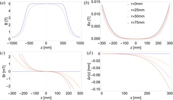
To illustrate the considerations involved, the field profile of a simple solenoid, with dimensions presented in Case 1 of table 1, is shown in figure 3(a) as dashed black line. The field maximum at $z=0$ of this solenoid-only configuration poses an issue in creating a magnetic mirror within the confinement region. Furthermore, this prominent curvature in $B$
 leads to a significant contribution of radial field component. For these reasons, corrections coils are required to achieve the design requirements. The resulting values for $\Delta B_z/B_0$
 , $\Delta B_r/B_0$
 , $\langle \Delta r \rangle$
 and $\theta$
 for the simple solenoid and corrected cases are summarized in table 2.
Magnetic field of the end-corrected solenoid (table 1, Case 2) operating at a current of $102.5$ A. (a) On axis profile over the extent of the end-corrected magnet (solid) compared with simple solenoid (dashed); (b) $z$
 component of field in the confinement region at radii $r = 0$
 (solid), $25$
 mm (dotted), $50$
 mm (dashed) and $75$
 mm (dot-dashed); (c) radial components of field at these radial locations; and (d) the corresponding deviations $\Delta r(z)$
 of the field lines centred at these radii, where $\Delta r$
 is symmetric about $z = 0$
 .

Measures of field-line bending in the confinement region of the MCT magnet, including the fractional variations of $B_z$ and $B_r$
 in per cent, the root-mean-square deviation in $r$
 along a field line at $r=50$
 mm and the angular deviation $\theta$
 from $z=0$
 to $250$
 mm. For Case 4, these metrics are evaluated over a confinement region of $z=0$
 to $120$
 mm.

Additional windings at the ends of solenoids are often implemented to improve overall homogeneity (Loney Reference Loney1966). They are used here to remove the central peak in $B$ at $z = 0$
 (cf. figure 3(a)). The number of turns and physical dimensions of the coils in $r$
 and $z$
 can adjusted to meet the design criteria given by (3.1) and to minimize $|B_r|$
 to the extent possible. An example of such a magnet design is Case 2 in table 1. The general features of this design, with discrete trim coils, are similar to that discussed in Dorbin et al. (Reference Dorbin, Enache, Dorbin, Dumitru, Pintea, Popovici and Zamfir2020). Optimization was done by following guidelines from Loney (Reference Loney1966, § 7) as well as trial and error: first imposing the constraint of (3.1), and then tuning the coil parameters to minimize $B_r$
 and hence $\langle \Delta r \rangle$
 . The resulting solution is neither unique nor completely optimized. While more sophisticated optimization techniques are available (Li et al. Reference Li, Ren and Wang2020, § 2.1), the approach described above proved to be adequate to meet the design goals.
Shown in figure 3 are the results for this design including the locations $B(r,z)$ of the field lines at the radii of $25$
 and $50$
 mm where the rings of off-axis cells would be located for Design (ii), and for comparison, outside of the confinement region at $75$
 mm. The axial profile has weak maxima at both ends of the confinement region, as shown in figures 3(a) and 3(b): there is a minimum at $z = 0$
 , and $B$
 increases continuously towards either end of the confinement region, thus eliminating magnetically trapped particles. The radial component of field shown in figure 3(c) has a reversed sign compared with that of the simple solenoid due to the change in sign of $\delta B_z/\delta z$
 . The variations of $B$
 for this design are $\Delta B_z/B_0=0.12\,$
 % and $\Delta B_r/B_0=0.05\,$
 % within the confinement region.
The maximum amplitude of $B_r$ in the confinement region is $2.7$
 mT at $r = 50$
 mm. Using (3.5), the corresponding angle $\theta$
 of a straight line from $z = 0$
 to $z = 250$
 mm connecting the ends of the field line in this interval is $\theta = 6.2 \times 10^{-5}$
 rad, an improvement of a factor of 15 over the simple solenoid. This value is comparable to the alignment of $\theta = 2.1 \times 10^{-4}$
 rad measured for a single PM trap (Singer et al. Reference Singer, Konig, Stoneking, Steinbrunner, Danielson, Schweikhard and Pedersen2021), and a subsequently determined value of approximately $5 \times 10^{-5}$
 rad for an MCT (Singer et al. Reference Singer, Danielson, König, Sunn Pedersen, Schweikhard and Stenson2023).
4.2 Optimized correction coils
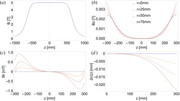
The overall homogeneity and amplitude of $B_r$ can be further improved by shifting the trim coils away from the main solenoid in both radius and axial position (Loney Reference Loney1966; Li et al. Reference Li, Ren and Wang2020) as illustrated by Case 3 of table 1. The results are shown in figure 4. The variations of $B$
 for this design are much smaller than for Cases 1 and 2: $\Delta B_z/B_0=0.04\,$
 % and $\Delta B_r/B_0=0.001\,$
 % within the confinement region.

As shown in figure 4(a), the on-axis profile is largely flat in the confinement volume. Although this configuration moves the maxima in $B_z$ (figure 4(b)) and $B_r$
 (figure 4(c)) closer to $z = 0$
 , they reside outside of the $\pm 250$
 mm axial extent planned for confinement, which still fulfils the constraint of (3.1). The maximum amplitude of $B_r$
 is $0.5$
 mT at $r = 50$
 mm in the confinement region and the corresponding angle $\theta$
 of a straight line from $z = 0$
 to $z = 250$
 mm connecting the ends of the field line is $\theta =1.9 \times 10^{-5}$
 rad. This is a factor of 48 (3) lower than the simple (end-corrected) solenoid. Additional details of the field profile over the extent of the confinement region are shown in figure 5, where the fractional variation $\Delta B/B_0$
 and the distribution of $B_r$
 are mapped in a two-dimensional colour scale.
Spatial distribution of (a) the non-uniformity in axial magnetic field $\Delta B/B_0$ and (b) the radial field. The MCT electrodes and the confinement region are outlined in (b).

Precise positioning of the trim coils would be required to realize these calculated results. In practice, variations in superconducting wire diameter and imperfections in wire placement within the magnet can lead to additional field variation. Furthermore, the forces due to energizing a superconducting magnet can be very large and even lead to deformation of the windings (Ren et al. Reference Ren, Wang, Chen and Chen2010). For this design case there is an expected $4.0 \times 10^5$ N of axial force on the trim coils and $3.0\times 10^8$
 Pa of radial pressure on the main solenoid, as calculated by integration using COMSOL. To gauge the feasibility of this design against foreseeable manufacturing imperfections, the simulation was repeated with one of the trim coils axially displaced from the optimized position by offsets between $\pm [0.5,5]$
 mm. While these perturbations led to asymmetric profile in $B_z$
 , no maxima emerged in the confinement region, thus still satisfying the design intent of excluding magnetic mirrors. For the largest offset, the amplitude of $B_r$
 is changed by ${\sim }1$
 mT on the side of the misaligned coil, which is still less than that of the end-corrected solenoid.
5 Experimental study of the effect of alignment on particle confinement
To our knowledge, beyond Fine (Reference Fine1988), Hart (Reference Hart1991) and Mitchell (Reference Mitchell1993) for PM traps and Heinzen et al. (Reference Heinzen, Bollinger, Moore, Itano and Wineland1991) for Penning traps, there are few quantitative data for the effect of magnetic field alignment on particle confinement. In the course of a recent experiment to develop an MCT, the experimental apparatus described in Singer et al. (Reference Singer, Konig, Stoneking, Steinbrunner, Danielson, Schweikhard and Pedersen2021, Reference Singer, Danielson, König, Sunn Pedersen, Schweikhard and Stenson2023) is equipped with the capability to study confinement of an electron plasma in a $3.1$ T field as a function of the misalignment of the confinement electrodes. Experiments are described here to study this effect for an on-axis SC to illustrate the deleterious effects of misalignment. No data are presently available for plasmas in off-axis cells.
The experimental results described in this section relate to the misalignment of assumed straight magnetic field lines oriented at an angle $\theta$ to the trap electrodes, rather than the bent field lines discussed above. While not directly comparable, the experimental results illustrate the important effect of such misalignments on particle confinement.
The prototype MCT has three SC (one on- and two off-axis) and a MC and is placed in a superconducting magnet with a $3.1$ T field (Singer et al. Reference Singer, Konig, Stoneking, Steinbrunner, Danielson, Schweikhard and Pedersen2021). The magnet was modelled in COMSOL, since the details of the magnet windings were unavailable (due to the age of the device). This was done by trial and error fitting to the experimentally measured on-axis near-field profile. The resulting specifications of the magnet are given in table 1 (Case 4).
Confinement as a function of misalignment was studied in the on-axis SC $S_{2}$ , using electrons. The structure is purposely misaligned by shifting the vacuum tube which holds the trap within the bore of the magnet, which is kept fixed. The plasmas span the region inside electrodes $S_{2.2}$
 to $S_{2.4}$
 with a $-300$
 V confinement potential applied to $S_{2.1}$
 and $S_{2.5}$
 . They have a length of $50$
 mm and an initial radius of $0.5$
 mm. For the well-aligned case, the shot-to-shot reproducibility is about $1\,$
 %. However, due to the change of the emitter position with respect to the trap when adjusting $\delta$
 , the reproducibility is as much as $7\,$
 % for the values of $\delta$
 shown in figure 7. The misalignment also changes the boundary conditions for the fill process. This results in a change in the amount of charge in the plasma as $\delta$
 is changed. Thus the cases for which data are presented here vary by about $7\,$
 % about the initial mean of $N\sim 2.7 \times 10^{8}$
 particles.
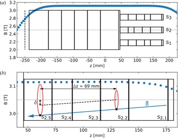
The radial distance $\delta$ between the centres of $S_{2.2}$
 and $S_{2.5}$
 was measured using the $m=1$
 diocotron mode technique described in Aoki et al. (Reference Aoki, Kiwamoto, Soga and Sanpei2004) and Singer et al. (Reference Singer, Konig, Stoneking, Steinbrunner, Danielson, Schweikhard and Pedersen2021). In figure 6(b), the distance $\delta$
 is defined as the distance between the centres of the diocotron orbits in $S_{2.2}$
 and $S_{2.5}$
 when projected onto one plane at the same magnetic field. The orbits are separated by an axial distance of $\Delta z = 69$
 mm. Converted to an angular alignment, $\delta = 203\ {\rm \mu}$
 m is equivalent to $\theta = 2.9 \times 10^{-3}$
 rad or $0.17\,^\circ$
 .
(a) Profile of the on-axis magnetic field (blue circles) overlapped with the electrode structure of the prototype MCT. It has one on-axis ($S_{2}$ ) and two off-axis ($S_{1}$
 , $S_{3}$
 ) SC which are shown on the right and a MC on the left. (b) An enlarged view of the on-axis SC $S_2$
 . The electrodes are denoted $S_{2.1}$
 to $S_{2.5}$
 . The blue arrow shows the direction of a magnetic field line which is tilted with respect to the electrode wall and directly connected to the electron emitter. The red ellipses show the dicotron orbits for plasmas confined in $S_{2.2}$
 and $S_{2.5}$
 , and the black stars indicate the initial position of the loaded plasmas. The dashed black line shows the centre position of the the $S_{2.2}$
 orbit when projected onto the obit of $S_{2.5}$
 . The distance $\delta$
 between the centres of the orbits and $\Delta z$
 are used to determine the angle of misalignment $\theta$
 .

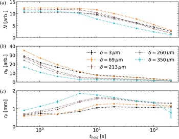
Figure 7 shows the results for the total charge $N$ , central density $n_{0}$
 and plasma radius $r_{p}$
 for five values of $\delta$
 (colour coded). Displayed here are measurements for $t_\textrm {hold} \ge 0.5$
 s. For earlier hold times, the camera image was saturated, preventing an accurate measurement of the central density. This is due to the camera and phosphor screen settings. They are constant for all measurements and chosen to enable the evaluation of the plasma profiles at larger confinement times. At $0.5$
 s, the central density and radius have already changed from their initial values: the radius has substantially increased from the initial $0.5$
 mm, and with it, the central density is reduced. This radial expansion and reduction of the central density is monotonically increasing with the misalignment $\delta$
 . The number of particles stays constant up to $10$
 s, except for the cases with $\delta = 213$
 and $350\ {\rm \mu}$
 m. Here the plasma has already lost charge after $5$
 and $2$
 s, respectively. For $\delta > 350\ {\rm \mu}$
 m, no data are available due to mechanical constraints on $\delta$
 .
Confinement as a function of the hold time $t_\textrm {hold}$ for different alignments of SC $S_{2}$
 , where $\delta$
 (colour coded) is the displacement of the centres of electrodes $S_{2.2}$
 and $S_{2.5}$
 : (a) number of particles $N$
 , (b) central density $n_0$
 and (c) plasma radius $r_p$
 . The dotted lines are included to guide the eye.

In a positron storage application, one would use the rotating wall (RW) technique (Danielson & Surko Reference Danielson and Surko2006a) to inhibit plasma expansion, but the RW must be turned off for some plasma manipulations. The measurements indicate this could be done without the RW for $2$ to $5$
 s without loss of particles for this range of misalignments. Minimum expansion is important, because RW compression will be applied for long-term particle confinement in the MCT, and the RW works best when the plasma is well confined, i.e. the radial extent of the plasma is small compared with the electrode inner radius. As shown in figure 7(c), this favours good alignment.
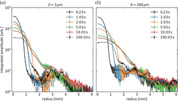
Over the course of the measurement, the plasma radius stays small compared with the wall radius, i.e. $r_{P} < r_{W} = 6$ mm, albeit losing charge. We suspected that this might be correlated to a plasma ‘halo’ that was observed to form at large hold times in a previous experiment (Hurst et al. Reference Hurst, Danielson, Baker and Surko2019). To check this assumption, figure 8 displays the angularly averaged plasma profiles for different hold times (colour coded) and for two alignment cases: the best aligned case with $\delta = 3\ {\rm \mu}$
 m (figure 8(a)) and a case with a misalignment of $\delta = 260\ {\rm \mu}$
 m (figure 8(b)). Both cases start with a similar amount of charge and the hold times are chosen so that the charge is constant for all of them except for $t_\textrm {hold} = 100$
 s (see figure 7(a)). In both cases there are defects on the screen. These defects lead to an increased background at radii from $2.7$
 to $4.1$
 mm in figure 8(a) and from $1.6$
 to $3.1$
 mm in figure 8(b). The usual noise floor of these profiles is ${\sim } 1 \times 10^{0}$
 .
Angularly averaged radial profiles for different hold times and two different misalignments: (a) the best aligned case $\delta = 3\ {\rm \mu}$ m and (b) with a misalignment of $\delta = 260\ {\rm \mu}$
 m. There are defects on the screen which lead to an increased background at radii (a) from $2.7$
 to $4.1$
 mm and (b) from $1.6$
 to $3.1$
 mm. The noise floor is $1 \times 10^{0}$
 .

In figure 8(a), at $t_\textrm {hold} = 0.23$ s the profile is a Gaussian with the maximum saturated. For increasing hold times, the central density decreases monotonically. At $1.03$
 s a second feature appears in the profile. It is visible as a step in the profile at a radius of ${\sim } 0.5$
 mm and grows more prominent with increasing hold time. From $1.03$
 to $5.03$
 s, while the central amplitude continues to drop, the step in the profile moves outward radially. At $t_\textrm {hold}=10$
 s the step in the profile has nearly vanished. A ‘halo’ (i.e. low-density region) has formed surrounding the plasma core. These halos are associated with increased transport (Hurst et al. Reference Hurst, Danielson, Baker and Surko2019). With further increased hold time, this halo moves radially outwards until it reaches the wall, resulting in a loss of charge. At $100.03$
 s, after halo plasma is lost to the wall, the plasma profile takes on a flap-top shape, indicating that it has reached a steady state. However, a small step is visible in the profile at $1.4$
 mm radius. The significance of this feature in the profile is currently unclear.
The temporal behaviour of the plasma profiles in figure 8(b) is the same as in figure 8(a): the central peak decreases monotonically with the hold time. At about $1.03$ s a halo begins to form around the central peak which slowly moves outward radially. The misalignment affects this behaviour in that increasing $\delta$
 increases the rate at which the central peak drops and the halo moves outward radially. Comparing the final profiles at $t_\textrm {hold}=100$
 s in figures 8(a) and 8(b), we see that an increased misalignment leads to a decrease in the central amplitude by a factor of 2, and an increase in the plasma radius. Both profiles display a flat-top shape which is expected for a thermalized non-neutral plasma in a PM trap (Driscoll, Malmberg & Fine Reference Driscoll, Malmberg and Fine1988; Dubin & O'Neil Reference Dubin and O'Neil1999; Danielson et al. Reference Danielson, Dubin, Greaves and Surko2015). The step at the plasma edge is slightly more prominent for $\delta = 260\ {\rm \mu}$
 m, suggesting that the halo formation might be increasing with $\delta$
 . However, the overlap of this region in figure 8(b) with the screen's defects prevents a definite conclusion.
For a practical MCT for $N\geq 10^{10}$ particles, the plasma length should be $\simeq 200$
 mm. Thus, if it is the maximum deviation of plasma from the magnetic axis that matters for good confinement, then the angular tolerance would be ${\sim }3$
 times smaller than that for the $69$
 mm long alignment distance relevant to figure 7. Assuming a $\delta = 203\ {\rm \mu}$
 m misalignment, this would correspond to $\theta \sim 1.0 \times 10^{-3}$
 rad for a $200$
 mm long plasma.
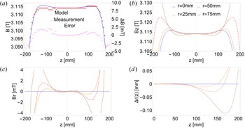
These misalignments were compared with the degree to which the field is bent (as per (3.3)) using the COMSOL model of the magnet (table 1, Case 4), and the results are shown in figure 9. The error in the model is low ($\le 4$ mT) in the range $z = \pm 200$
 mm where the electrodes are placed.
(a) Measurement and (b–d) model of the magnetic field for the magnet used in Singer et al. (Reference Singer, Konig, Stoneking, Steinbrunner, Danielson, Schweikhard and Pedersen2021, Reference Singer, Danielson, König, Sunn Pedersen, Schweikhard and Stenson2023) (table 1, Case 4) in similar format to figure 3, but focused on a smaller region of uniformity of $\pm 200$ mm.

The model is used to investigate the magnetic field profile on and off axis as was done for the other cases in table 1. Figure 9 shows the $r$ and $z$
 components of $B$
 as well as the deviations of the field lines calculated with (3.5). The higher resolution of figure 9(b) shows the $B_z$
 profile with maxima at different $z$
 values for different radial locations. Figures 9(c) and 9(d) show the radial field and corresponding field line curvature for the model which is similar in amplitude to that of Case 2, although with a shorter region of uniformity. Beyond $\pm \sim 140$
 mm, the field falls off sharply.
The optimum confinement region for this model is thus limited to $\pm \sim 120$ mm from the centre in order to exclude magnetic maxima. Using (3.5), the angular deviation of the $r=50$
 mm field line from $z=[0,120]$
 mm is $\theta = 9.4\times 10^{-5}$
 rad, which is close to the minimum measurable value reported in Singer et al. (Reference Singer, Konig, Stoneking, Steinbrunner, Danielson, Schweikhard and Pedersen2021). If the on-axis confinement results are valid off axis, the field line bending is sufficiently small as to not present a problem and even has a safety factor of ${\sim }4$
 for a $200$
 mm long plasma.
6 Summary and concluding remarks
Presented here are the considerations relevant to the design of a solenoid optimized for a MCT for the accumulation of large numbers of positrons. Since the MCT architecture requires PM cells both on and off the magnetic axis, the required magnetic field is further constrained beyond that required for on-axis PM traps. For good confinement, the magnetic field lines should be straight and parallel to the axes of the cylindrical confining electrodes.
Assuming that magnetically trapped particles are an important consideration for good confinement, there should also be no magnetic field maxima (i.e. ‘magnetic mirrors’) in the confinement region. To ensure the absence of these maxima, the magnetic field is tailored to avoid maxima in the confinement region, which results in a radial component of $B$ and hence some field-line bending. While this effect is absent on axis, it can be important for off-axis SC, such as those required in present MCT designs.
While electrostatic particle trapping is also an important consideration for good confinement, it has not been considered here. Also not considered here are added coils that would be necessary to shield the magnetic field far from the confinement region to mitigate deleterious effects on nearby apparatus and beam lines. This could be done by configurations such as those described in Li et al. (Reference Li, Ren and Wang2020).
A design is presented for a $5$ T magnet which eliminates magnetic mirrors by arranging a small positive spatial curvature of the magnetic field, and this results in an acceptably small amount of field-line deviation. There are two caveats to this design. This coil configuration is almost certainly not unique in producing an acceptable magnetic field structure for good particle confinement. Further, for the coil designs presented in table 1, little consideration has been given to practical construction details beyond simple estimates of acceptable forces on magnet coils and the tension in superconducting coil windings.
One consideration is discussed here, which to our knowledge has been neglected in previous work. This relates to the fact that field-line bending in PM traps due to finite $\partial B/\partial z$ should, in principle, lead to enhanced particle transport (i.e. beyond the simple misalignment of straight field lines in the confinement electrodes). This would benefit from further theoretical and experimental work.
Also presented were data for electron confinement in a SC as a function of the alignment of the electrodes with respect to the magnetic axis. Among other results, this study highlights the importance of the low-density ‘halo’ plasma between the core plasma and the electrode wall. More extensive studies of these effects, and particularly confinement in off-axis cells, will be necessary to optimize the design of a high-capacity MCT.
Acknowledgements
The authors and editor Francesco Califano thank the referees for their advice in evaluating this article.
Funding
This work is supported by the US Department of Energy (C.M.S., J.R.D., D.R.W., grant DE-SC0016532); the Deutsche Forschungsgemeinschaft (M.S., grants SCHW 401/23-1, HU 978/15-1 and PE 2655/1-1); and the European Research Council (M.S., grant 741322).
Declaration of interest
The authors report no conflict of interest.