1. Introduction
Conventional robotic manipulators have high rigidity due their its link’s composition (usually metallic alloys), the use of transmission systems (as harmonic drives) and electric motor’s constructive aspect. This high rigidity provides precision, repeatability, reliability, high payload and has guided mechatronic designs of robotic devices for decades.
With increased human–robot physical interaction in recent years, whether in collaborative or assistive robotics, the high rigidity of conventional manipulators can cause lethal accidents. The risk of operator death or equipment breakdown in a collision event has led to the need to replace electric motors and transmission systems with compliant actuators. Thus, the use of mechanisms driven by variable stiffness actuators (VSA) seeks a compromise between accuracy, repeatability, reliability and safety [Reference Vanderborght, Albu-Schäffer, Bicchi, Burdet, Caldwell, Carloni and Garabini1,Reference Jafari, Tsagarakis and Caldwell2]. Therefore, various types of compliant actuators and flexible links have been proposed [Reference Park, Kim, Song and Kim3].
One of the strongest candidates is the McKibben muscle. Nuclear physicist Joseph Laws McKibben developed this actuator in the 1950s [Reference Chou and Hannaford4], which was primarily used as a low-cost orthosis in patients who had suffered polio. In its constructive aspect, the McKibben muscle consists of two polymers and connectors. Internally there is a tube of elastomer surrounded by a mesh of thermoplastic material. Both ends are covered with connectors for fixing and tightness. When compressed air is fed to the system, the latex expands to a limit defined by the outer mesh and the actuator performs work [Reference Chou and Hannaford4–Reference Jiang, Xiong, Sun, Huang and Xiong7].
As advantages, when compared to electric motors, the McKibben muscle presents high specific power, variable stiffness, absence of metallic parts and sparks during operation, absorption of mechanical shocks and suppression of power peaks during collisions. In contrast, the actuator has nonlinearities due to the effects of hysteresis, intrinsic to elastomers, presence of dead zone and nonlinear Coulomb friction. Muscles’s nonlinearities added to the manipulator’s kinematic and dynamics equations make the kinematic modelling complex. It is worth mentioning that there are other nonlinearities related to the pneumatic circuit, which are valve saturation and dead zone. Thus, one of the controller’s main tasks is to compensate these nonlinearities, ensuring precision and stability [Reference Tondu and Lopez8–Reference Irshaidat, Soufian, Al-Ibadi and Nefti-Meziani16].
Thus, it becomes prohibitive to use classical control techniques, such as proportional integral derivative (PID) controller, as different operational conditions or changes in set-point require a new tuning. Due to the aforementioned fact, robotic mechanisms driven by VSA that use advanced control techniques, such as model-based control (MBC) [Reference Shen17–Reference Huang, Qian, Liu, Wang, Xiong and Ri22], intelligent control [Reference Thanh and Ahn23–Reference Anh26] and adaptive controllers [Reference Zhang and Wei27–Reference MouČka30] can be found in the literature.
As practical applications, the control system can be used in assistive and collaborative robotics. In the field of assistive robotics, the mechanism can be used in rehabilitation equipment, surgery, orthoses and prostheses. In collaborative robotics, the purpose may be to assist the operator, especially in assembly and inspection tasks.
In robotic rehabilitation equipment, the machine has healthy people patterns to be followed by the patient. Consequently, it is important that these patterns and commands can be inserted into a reference model so that the patient can practice the recovery exercises. In surgery, orthoses, prostheses, and collaborative robotics it is important that the control system is model-free, which makes the control system’s design less complex and facilitates the implementation. Another important feature of the control system is that it has to be asymptotically stable. This guarantees zero error in steady state and high precision in tracking the trajectory.
In summary, the design premises for the proposed control system are:
-
1. operate in real time;
-
2. adjustable transient regime according to a reference model;
-
3. compensation of nonlinearities;
-
4. present asymptotic convergence for position tracking;
-
5. reject disturbances and
-
6. less complex design (model free).
Thus, the Model Reference Adaptive Controller (MRAC) was selected, as there is no need for a plant’s nominal model, which eliminates the need to identify parameters, facilitating real-time operations and making the control system design less complex and with fewer steps. Another MRAC’s advantage is that the expected performance can be defined through the reference model, in which the performance in terms of maximum overshooting and settling time can be defined. Another important feature of MRAC is that the stability analysis is embedded in the controller design, which removes the need for a posteriori stability analysis [Reference Aström and Wittenmark31,Reference Bomfim32].
A disadvantage is that during the period of parameters convergence, the control action has a weak effect on the plant, which implies a high trajectory error during set-point changes and disturbance rejection. To mitigate this effect, PID controller is used in conjunction with MRAC, and the PID operates during the transient regime.
This approach will be called Hybrid MRAC (H-MRAC) in this work. The hybrid controller (PID + MRAC) was originally proposed in 1986 by Horowitz and Tomizuka [Reference Horowitz and Tomizuka33]. Since then, other researchers such as Zhang and Wei [Reference Zhang and Wei27] have proposed new topological approaches to the control law. In this research, a new control law was proposed and obtained better results than those proposed in the literature.
In this article, a two degrees of freedom (DoF) manipulator is modelled using pneumatic artificial muscles in agonist/antagonist configuration. The muscles are modelled considering the effects of force, pressure and flow dynamics. The control system is then modelled and Lyapunov’s theory is used in its design, ensuring asymptotic stability.
H-MRAC performance was compared with MRAC and the controller developed by Zhang and Wei [Reference Zhang and Wei27], entitled Adaptive PID or A-PID. The three controllers were also implemented in the manipulator for simulations and real-world tests.
In its organizational aspect, this article is divided into seven sections. Section 2 aims to present the background and problem formalisation. Section 3 presents the proposed methodology for formulating the adaptive control theory. Section 4 is responsible for presenting the simulations in a Matlab/Simulink
 $^{\circledR}$
environment. Section 5 presents the experimental apparatus and results. In the Section 6, the human–robot safety interaction is analysed. Section 7 is responsible for presenting the final remarks and suggestions for future researches.
2. Problem Formalisation
Kinematic and dynamic equations of articulated mechanisms with two or more DoF are nonlinear and coupled models. When McKibben muscles are used as actuators, hysteresis, dead band and Coulomb friction effects are added to nonlinearities. In general, kinematic and dynamic models of robotic manipulators are well consolidated in the literature [Reference Craig34–Reference Niku37], and it is up to the present research to present the integration between these equations and the phenomenological models proposed for the actuators and valves. The analysis of this work is restricted to the Configuration Space. The following hypotheses were taken into consideration:
-
1. manipulator’s links are rigid;
-
2. real-time operation considers that the system responds in less than 200 ms;
-
3. parameters do not vary with time, but with the manipulator’s configuration and
-
4. temperature remains constant during the experiments (polytropic index = 1 - isothermal process).
2.1. Nonlinear model of an agonist/antagonist joint driven by McKibben muscle
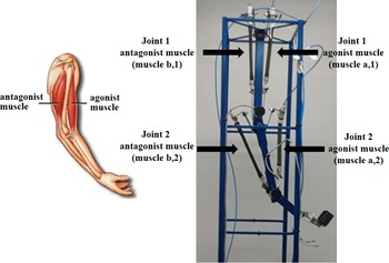
According to Shen [Reference Shen17], there are four processes for the dynamic modelling of a robotic joint driven by McKibben muscles in the agonist/antagonist configuration. The processes consist of dynamic load modelling, with the incorporation of force, pressure and flow dynamics. Figure 1 shows the agonist/antagonist configuration used for mechanism’s design. From the figure, it can be seen that the project consists of biological mimicry, in which the configuration allows the joints to move in clockwise and counterclockwise directions.
Agonist and antagonist muscle. On the left a human elbow and on the right the elbow manipulator were used in this research.

Considering that the muscular activation is usually carried out by proportional pressure or flow regulating valves, it is extremely important to relate the variables mentioned above. As a starting point, Eq. (1) relates muscle’s force to the joint angular acceleration.
 \begin{equation} \ddot q_n = \frac{1}{J_n}[(F_{b,n} - F_{a,n})r_n - B_n \dot q_n],\end{equation}
where n is joint number;
 $\ddot q_n$
is joint angular acceleration (rad/s2);
 $J_n$
is the moment of inertia (kgm2);
 $B_n$
is the joint damping (Nms2/rad);
 $F_{a,n}$
is agonist muscle contraction force (N);
 $F_{b,n}$
is antagonist (N);
 $r_n$
is the pulley radius.
Incorporating the force’s dynamics [Reference Shen17], Eq. (1) can be rewritten as follows:
 \begin{equation} \ddot q_n = \left ( \left [ \frac{3(\varepsilon _{0b,n}-\varepsilon _{b,n})^2-\rho^2}{4\pi N_r^2J_n} \right ](Pr_{b,n}-Pr_{atm}) -\left [ \frac{3(\varepsilon _{0a,n}+\varepsilon _{a,n})^2-\rho^2}{4\pi N_r^2 J_n} \right ](Pr_{a,n}-Pr_{atm}) \right )r_n -\frac{B_n}{J_n}\dot q_n,\end{equation}
where
 $\dot q_n $
is joint angular velocity (rad/s);
 $Pr_{a,n}$
is pressure in the agonist muscle (bar);
 $Pr_{b,n}$
is pressure in the antagonist muscle (bar);
 $Pr_{atm}$
is atmospheric pressure (bar);
 $\varepsilon _{0a,n}$
and
 $\varepsilon _{0b,n}$
are muscles’s initial lengths (m);
 $\varepsilon _{a,n}$
and
 $\varepsilon _{b,n}$
are the muscles’s current lengths (m);
 $N_r$
is thread’s number of turns and
 $\rho$
is the thread length.
 $N_r$
and
 $\rho$
have the same value for all muscles.
Incorporating pressure’s dynamics [Reference Shen17], Eq. (2) can be rewritten as follows:
 \begin{equation} \dddot q_n = \left ( \frac{c_{b,n}}{J_n}\dot m_{b,n}-\frac{c_{a,n}}{J_n} \dot m_{a,n} -\frac{\kappa_n}{J_n}\dot q \right)r_n -\frac{B_n}{J_n}\ddot q_n,\end{equation}
 \begin{equation} c_{a,n}= \frac{\eta R\, T_{a,n} [3(\varepsilon _{0a,n}+\varepsilon _{a,n})^2-\rho^2]}{(\varepsilon _{0a,n}+\varepsilon _{a,n})[\rho^2-(\varepsilon _{0a,n}+\varepsilon _{a,n})^2]},\end{equation}
 \begin{equation} c_{b,n}= \frac{\eta R\, T_{b,n} [3(\varepsilon _{0b,n}-\varepsilon _{b,n})^2-\rho^2]}{(\varepsilon _{0b,n}-\varepsilon _{b,n})[\rho^2-(\varepsilon _{0b,n}-\varepsilon _{b,n})^2]},\end{equation}
 \begin{align} \kappa_n&= \frac{3[(\varepsilon _{0b,n}-\varepsilon _{b,n})(Pr_{b,n}-Pr_{atm}) + (\varepsilon _{0a,n}+\varepsilon _{a,n})(Pr_{a,n}-Pr_{atm})]}{2\pi N_r^2} \nonumber \\[4pt] &\quad + \frac{\eta [3(\varepsilon _{0a,n}+\varepsilon _{a,n})^2-b^2]^2Pr_{a,n}}{4\pi N_r^2 (\varepsilon _{0a,n}+\varepsilon _{a,n})[\rho^2-(\varepsilon _{0a,n}+\varepsilon _{a,n})^2]} + \frac{\eta [3(\varepsilon _{0b,n}+\varepsilon _{b,n})^2-\rho^2]^2Pr_{b,n}}{4\pi N_r^2 (\varepsilon _{0b,n}-\varepsilon _{b,n})[\rho^2-(\varepsilon _{0b,n}-\varepsilon _{b,n})^2]}, \end{align}
where
 $\dddot q_n$
is joint angular jerk (rad/s3);
 $\dot m_{a,n}$
and
 $\dot m_{b,n}$
are volumetric flows into or out of each PAM (m3/s);
 $\eta$
is ratio of specific heats; R is universal gas constant (0.287 kJ/kgK);
 $T_{a,n}$
and
 $T_{b,n}$
are muscles’s absolute temperatures (K).
Equations (7) and (8) algebraically relates the mass flow to the valve area command. In this case, the mass flow through the valve can be modelled as a ideal gas flow through a converging nozzle.
 \begin{equation}\dot m_{a,n}(Pr_u, Pr_d) = A_{a,n} \Psi_{a,n}(Pr_u, Pr_d),\end{equation}
 \begin{equation}\dot m_{b,n}(Pr_u, Pr_d) = A_{b,n} \Psi_{b,n}(Pr_u, Pr_d),\end{equation}
where
 $A_{a,n}$
and
 $A_{b,n}$
are effective valve opening area (m2);
 $Pr_u$
is upstream pressure (bar) and
 $Pr_d$
is downstream pressure (bar);
 $\Psi_{a,n}$
and
 $\Psi_{b,n}$
are given by Eq. (9).
 \begin{equation} \Psi_{\mu,n} (Pr_u, Pr_d)= \begin{cases}\sqrt{\dfrac{\eta}{RT_{\mu,n}} \left ( \frac{2}{\eta +1} \right ) ^ {\left ( \frac{\eta+1}{\eta-1} \right )} } C_{f\mu,n}Pr_u & \text{if} \, \, \frac{Pr_d}{Pr_u} \leq C_{r\mu,n} \,\, \text{(chocked)}\\ \\[-7pt] \sqrt{\dfrac{2\eta}{RT_{\mu,n}(\eta-1)}} \sqrt{1-\left ( \dfrac{Pr_d}{Pr_u} \right )^{\left ( \frac{\eta -1}{\eta} \right )}}\left ( \frac{Pr_d}{Pr_u} \right )^\frac{1}{\eta} C_{f\mu,n}Pr_u & \text{otherwise} \, \, \text{(unchocked)}\end{cases},\end{equation}
where
 $\mu$
refers to agonist (a) or antagonist (b) muscle;
 $C_f$
is valve’s discharge coefficient and
 $C_r$
is the pressure ratio.
Incorporating flow’s dynamics, Eq. (3) can be rewritten as follows:
 \begin{equation} \dddot q_n =\left [ \left( \frac{c_{a,n}\Psi_{a,n} - c_{b,n}\Psi_{b,n}}{J_n}\right )(A_{a,n}-A_{b,n}) -\frac{\kappa_n}{J_n}\dot q_n \right ]r_n-\frac{B_n}{J_n}\ddot q_n,\end{equation}
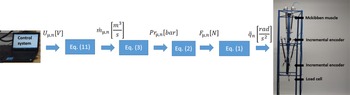
Figure 2 shows how the sequence of equations should be used. If the control system has a flow regulating valve, the initial step is Eq. (10). For a pressure regulating valve, modelling starts at Eq. (3). Equation (11) represents the relation between the computer signal (
 $U_{\mu,n}$
) and the effective valve opening area (
 $A_{\mu,n}$
).
 \begin{equation} U_{\mu,n} = z_k A_{\mu,n},\end{equation}
where
 $z_k$
is a constant.
Four processes for the dynamic modelling of a robotic joint driven by McKibben muscles in the agonist/antagonist configuration according to Shen [Reference Shen17].

Due to high number of parameters and sensors’ cost, in Eq.(10) several authors [Reference Jiang, Xiong, Sun, Huang and Xiong7,Reference Serres, Reynolds, Phillips, Gerschutz and Repperger38–Reference Bomfim and Lima II41] propose the development of linearised phenomenological models based on the transfer function. Such models have high correlation coefficients, above 0.9, and are presented in the next topic.
2.2. Transfer function with variable parameters
From a dynamic point of view, the muscle can be modelled in analogy to a mass-spring-damper system. Thus, Eq. (12) presents the actuator’s behaviour [Reference Reynolds, Repperger, Phillips and Bandry42]. It should be noted that the phenomenological model is for a muscle with a coupled load.
 \begin{equation} M \ddot x + B \dot x + K x = \|\mathbf{F_c}\| - Mg,\end{equation}
where M is the load (kg); B is the damping (Ns/m); K is the muscle stiffness (N/m);
 $\|\mathbf{F_c}\|$
is contraction force’s euclidean norm (N) and x is the muscle linear displacement (m).
In Jiang et al. [Reference Jiang, Xiong, Sun, Huang and Xiong7], a transfer function was proposed to relate the joint angle to the input pressure. Considering that the muscular response and the mechanism are nonlinear, Bomfim and Lima II [Reference Bomfim and Lima II41] proposed a second-order model, based on transfer function, in which the parameters are adjusted (BLII methodology). The adjustment is made according to the muscle pressure and load on the manipulator’s end-effector. Eq. (13) represents the joint’s equivalent natural frequency (
 $\omega_{neq}$
), Eq. (14) represents the equivalent damping coefficient (
 $\xi_{eq}$
) and G(s) is the joint’s transfer function that relates the angle to the input pressure. With Eq. (15), correlation coefficients of 0.93 were obtained by Bomfim and Lima II [Reference Bomfim and Lima II41]. It should be noted that the phenomenological model is for an 1-DoF manipulator.
 \begin{equation} \omega_{neq}(\|\mathbf{F_e}\|) = 0.1342\|\mathbf{F_e}\|^2 - 2.0645\|\mathbf{F_e}\| + 5.1487,\end{equation}
 \begin{equation} \xi_{eq}(\|\mathbf{F_e}\|)= 0.0013\|\mathbf{F_e}\|^2 -0.0205\|\mathbf{F_e}\|+0.1256,\end{equation}
 \begin{equation} G(s) = (8.3333Pr_{b} -2.8000\|\mathbf{F_e}\|-4.0000)\left ( \frac{\omega_{neq}^2}{s^2+2\xi_{eq}\omega_{neq}s+\omega_{neq}^2} \right ),\end{equation}
where
 $Pr_b$
is the antagonist muscular pressure (bar) and
 $\|\mathbf{F_e}\|$
is the force’s euclidean norm on the manipulator’s end-effector (N).
BLII methodology [Reference Bomfim and Lima II41] has the purpose of developing a quick and simple way of obtaining a linearised model for the mechanism, in view of the complex task of measuring the variables’ values in Eqs. (3) and (10), mainly due to sensors costs. BLII methodology will be used in the present work simulations (Section 4).
3. Controller Synthesis
3.1. Controller’s structure
In this work, the control law proposed for a robotic joint can be given by Eq. (16) in the generalised form:
 \begin{equation} u = \theta_1 u_c -\theta_2 \dot y - \theta_3 y,\end{equation}
where
 $\theta$
are adjustment parameters; u is the adaptive control law;
 $u_c$
is PID controller output and y is the system output.
The reference model to be tracked by the controller can be given by the transfer function represented in Eq. (17). In this equation, it is considered the expected plant’s performance in terms of overshoot, rise and settling times, which can be controlled indirectly by
 $\xi$
and
 $\omega_n$
values.
 \begin{equation} G_m(s)= \frac{Y_m(s)}{U_c(s)} = \frac{\lambda \omega_n^2}{s^2+2\xi \omega_n s+\omega_n^2} = \frac{\beta_m}{s^2+\alpha_{1m}s+\alpha_{2m}},\end{equation}
where
 $Y_m$
is the reference model’s output;
 $U_c$
is the reference or command signal and
 $\lambda$
is the static gain.
According to the Eq. (17), the reference model can also be given depending on the parameters
 $\alpha_{1m}=2\xi\omega_n$
,
 $\alpha_{2m}=\omega_n^2$
and
 $\beta_{m}=\lambda\omega_n^2$
, that are strictly positive.
In works developed by Jiang et al. [Reference Jiang, Xiong, Sun, Huang and Xiong7], robotic joint’s behaviour is modelled using a second order transfer function. Thus, in the present research, the Eq. (18) describes the joint’s phenomenological model.
 \begin{equation} G(s)=\frac{Y(s)}{U(s)} = \frac{\beta}{s^2+\alpha_{1}s+\alpha_{2}}.\end{equation}
In general, the error e is given by:
 \begin{equation} e = y - y_m,\end{equation}
where y and
 $y_m$
are the joint’s output and desired output, respectively.
3.2. Lyapunov’s stability theory
The controller proposed in this article is based on the MRAC. With this family of controllers is not necessary to obtain the plant’s phenomenological models or to perform the identification process, considering that the structure is model-free (Section 2 is intended to provide data for simulations). Lyapunov’s theory was used to develop the control law’s topological structure, as the analysis and asymptotic stability guarantee for the control system already comprises the steps for the project from Lyapunov’s direct method perspective [Reference Khalil and Grizzle10,Reference Aström and Wittenmark31].
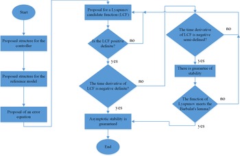
Meeting Lyapunov’s prerogatives is a sufficient condition, but not necessary to guarantee the asymptotic stability of a system. If the LCF time derivative is semi-defined negative and meets the Barbalat’s lemma, asymptotic stability is guaranteed. Thus, Fig. 3 presents a flowchart with the main stages used in this work for control system design.
Flowchart with main stages for control design based on Khalil and Grizzle [Reference Khalil and Grizzle10] and Aström and Wittenmark [Reference Aström and Wittenmark31].

3.3. Lyapunov candidate function and hybrid adaptive control law
As a rule, LCFs are quadratic functions that have the purpose of ensuring stability for the system. That said, the following theorem is enunciated.
Theorem 3.1. (Stability analysis in the Lyapunov’s sense) Consider the hybrid adaptive control problem of a robotic joint in the agonist/antagonist configuration. Assuming a linearised model through a strictly positive real transfer function, Eq. (20) was proposed as the LCF for the manipulator; adjustment parameters are represented by Eqs. (21), (22) and (23) and
 $\dot{V}$
is negative semi-definite.
 \begin{equation} V(e, \dot{e}, \theta, \Gamma)=\underset{V_1}{\underbrace{\frac{1}{2} \Biggl (\Gamma_1 e^2 + 2\Gamma_2 e\dot{e} +\Gamma_3 \dot{e}^2\Biggl ) }} \, + \,\underset{V_2}{\underbrace{\frac{(\beta\theta_1-\beta_m)^2}{2\beta\gamma_1}+\frac{(\beta\theta_2 + \alpha_1-\alpha_{1m})^2}{2\beta\gamma_2}+\frac{(\beta\theta_3 + \alpha_2-\alpha_{2m})^2}{2\beta\gamma_3} }},\end{equation}
where
 $\Gamma_1$
,
 $\Gamma_2$
and
 $\Gamma_3$
are strictly positive constants and
 $\gamma_1$
,
 $\gamma_2$
and
 $\gamma_3$
the adaptation gains, also, strictly positives.
 \begin{equation} \dot{\theta}_1 = -\gamma_1(\Gamma_2e + \Gamma_3\dot{e})u_c,\end{equation}
 \begin{equation} \dot{\theta}_2 = \gamma_2(\Gamma_2e + \Gamma_3\dot{e})\dot{y},\end{equation}
 \begin{equation} \dot{\theta}_3 = \gamma_3(\Gamma_2e + \Gamma_3\dot{e})y.\end{equation}
Proof. For the candidate function V, in Eq. (20), to be is a positive definite function it is necessary that
 $\Gamma_1 \Gamma_3 > \Gamma_2^2$
. This fact can be seen in the Appendix A. Then, following the Fig. 3 scheme, the next step shows that
 $\dot{V}$
is negative semi-definite. The LCF’s time derivative is given by:
 \begin{equation} \dot{V}= \Gamma_1 e \dot{e} + \Gamma_2\dot{e}^2 + (\Gamma_2 e +\Gamma_3 \dot{e})\ddot{e} +\frac{(\beta\theta_1-\beta_m)}{\gamma_1}\dot{\theta}_1+\frac{(\beta\theta_2 + \alpha_1-\alpha_{1m})}{\gamma_2}\dot{\theta}_2+\frac{(\beta\theta_3 + \alpha_2-\alpha_{2m})}{\gamma_3}\dot{\theta}_3.\end{equation}
Substituting Eqs. (21), (22) and (23) in Eq. (24), is obtained:
 \begin{align} \dot{V} &= \Gamma_1 e \dot{e} + \Gamma_2\dot{e}^2 + (\Gamma_2 e +\Gamma_3 \dot{e})\ddot{e} +\frac{(\beta\theta_1-\beta_m)}{\gamma_1}(-\gamma_1(\Gamma_2e + \Gamma_3\dot{e})u_c)\nonumber\\[3pt] &\quad +\frac{(\beta\theta_2 + \alpha_1-\alpha_{1m})}{\gamma_2}(\gamma_2(\Gamma_2e+ \Gamma_3\dot{e})\dot{y}) +\frac{(\beta\theta_3 + \alpha_2-\alpha_{2m})}{\gamma_3}(\gamma_3(\Gamma_2e + \Gamma_3\dot{e})y). \end{align}
Simplifying and rearranging the terms in Eq. (25):
 \begin{multline} \dot{V}= \Gamma_1 e \dot{e} + \Gamma_2\dot{e}^2 + (\Gamma_2 e +\Gamma_3 \dot{e})\Biggl (\ddot{e} - (\beta\theta_1-\beta_m)u_c+(\beta\theta_2 + \alpha_1-\alpha_{1m}) \dot{y}+(\beta\theta_3 + \alpha_2-\alpha_{2m})y\Biggl ).\end{multline}
The general equation for
 $\ddot{e}$
is given by Eq. (27), as can be seen in detail in the Appendix B.
 \begin{equation} \ddot{e}=-\alpha_{1m}\dot{e}-\alpha_{2m}e +(\beta\theta_1-\beta_m)u_c - (\beta\theta_3 + \alpha_2-\alpha_{2m})y -(\beta\theta_2 + \alpha_1-\alpha_{1m})\dot{y} .\end{equation}
Substituting equation of the
 $\ddot{e}$
, presented by Eq. (27), in Eq. (26):
 \begin{align} \dot{V}&= \Gamma_1 e \dot{e} + \Gamma_2\dot{e}^2 + (\Gamma_2 e +\Gamma_3 \dot{e})\Biggl (-\alpha_{1m}\dot{e}-\alpha_{2m}e +(\beta\theta_1-\beta_m)u_c - (\beta\theta_3 + \alpha_2-\alpha_{2m})y\nonumber\\[3pt] &\quad -(\beta\theta_2 + \alpha_1-\alpha_{1m})\dot{y}- (\beta\theta_1-\beta_m)u_c+(\beta\theta_2 + \alpha_1-\alpha_{1m}) \dot{y}+(\beta\theta_3 + \alpha_2-\alpha_{2m})y\Biggl ). \end{align}
Simplifying and rearranging the terms:
 \begin{equation} \dot{V}= \Gamma_1 e \dot{e} + \Gamma_2\dot{e}^2 + (\Gamma_2 e +\Gamma_3 \dot{e}) (-\alpha_{1m}\dot{e}-\alpha_{2m}e ),\end{equation}
 \begin{equation} \dot{V}= e\dot{e}(\Gamma_1-\alpha_{1m}\Gamma_2-\alpha_{2m}\Gamma_3) + \dot{e}^2(\Gamma_2 -\alpha_{1m}\Gamma_3) -\alpha_{2m}\Gamma_2e^2.\end{equation}
In the Appendix C, relationships between the parameters
 $\Gamma_1$
,
 $\Gamma_2$
and
 $\Gamma_3$
are performed. Thus, obtaining the following equations:
 \begin{equation} \Gamma_1 = \left ( \frac{\alpha_{1m}^2+\alpha_{2m}}{\alpha_{1m}\alpha_{2m}} \right ) \delta_2+ \delta_1 \alpha_{2m},\end{equation}
 \begin{equation} \Gamma_3= \frac{\delta_2}{\alpha_{1m}\alpha_{2m}} + \delta_1 .\end{equation}
where
 $\delta_1$
and
 $\delta_2=\Gamma_2\alpha_{2m}$
are strictly positive.
Replacing the terms
 $\Gamma_1$
and
 $\Gamma_3$
by Eqs. (31) and (32), respectively; and taking
 $\Gamma_2=\delta_2/\alpha_{2m}$
:
 \begin{align} \dot{V}&= e\dot{e}\Biggl [\left ( \frac{\alpha_{1m}^2+\alpha_{2m}}{\alpha_{1m}\alpha_{2m}} \right ) \delta_2+ \delta_1 \alpha_{2m} -\alpha_{1m}\frac{\delta_2}{\alpha_{2m}}- \alpha_{2m}\left (\frac{\delta_2}{\alpha_{1m}\alpha_{2m}} + \delta_1 \right ) \Biggl ] \nonumber\\[3pt] &\quad + \dot{e}^2\Biggl [ \frac{\delta_2}{\alpha_{2m}} -\alpha_{1m}\left (\frac{\delta_2}{\alpha_{1m}\alpha_{2m}} + \delta_1 \right ) \Biggl ] - \delta_2e^2. \end{align}
Simplifying and rearranging the terms:
 \begin{equation} \dot{V}= -\alpha_{1m} \delta_1\dot{e}^2 - \delta_2e^2. \end{equation}
The function represented by Eq. (34) is negative semi-defined. Thus, it can be concluded that the system is stable in the Lyapunov’s sense and Eq. (20) is a Lyapunov’s function. To guarantee asymptotic stability, it is necessary to comply with the Barbalat’s lemma.
Then, to use the Barbalat’s lemma [Reference Khalil and Grizzle10], it is taken
 $\Phi= \dot{V}= -\alpha_{1m} \delta_1\dot{e}^2 - \delta_2e^2$
, and its time derivative is given by:
 \begin{equation} \dot{\Phi}= -2\alpha_{1m} \delta_1\dot{e} \ddot{e} - 2\delta_2e\dot{e}. \end{equation}
In Eq. (35), the terms e and
 $\dot{e}$
are limited since the system is stable in the Lyapunov’s sense. If the system reference signal is limited, the term
 $\ddot{e}$
will also be limited, since the system is stable in the Lyapunov sense. Therefore,
 $|\dot{\Phi}|$
is limited and
 $\Phi$
is a uniformly continuous function. Thus, the
 \begin{equation} \lim_{t\rightarrow \infty} \int_0^t\Phi(\zeta)d\zeta =V(\infty)-V(0)=\sigma <\infty, \end{equation}
where
 $\sigma$
is a positive parameter.
As V is a Lyapunov’s function, V is positive definite and
 $V(0)=0$
. And once that
 $\dot{V} \leq0$
,
 $V(\infty)$
exists and is limited. Then, by the Barbalat’s lemma [Reference Khalil and Grizzle10], it is concluded that
 $\lim_{t\rightarrow \infty} \Phi(t)=0$
, which implies that
 $\lim_{t\rightarrow \infty} e^2=0$
, that is, that the error will be null in steady state. Therefore, the system’s asymptotic stability is guaranteed. Being proven the asymptotic stability, the parameters
 $\Gamma_1=2$
,
 $\Gamma_2=1$
and
 $\Gamma_3=1$
were chosen for the design in simulations and experiments.
3.4. Proposed control system block diagram and benchmarking
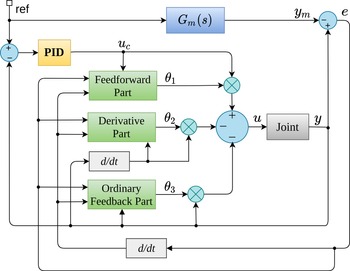
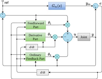
Figure 4 shows the proposed H-MRAC. The controller MRAC can be divided into three parts analytically described by Eqs. (21), (22) and (23). The first part consists of a feedforward controller. The second part is a derivative and the third is an ordinary feedback. The feedforward part has the purpose of adding an anticipatory control action to the system, mitigating the effects of disturbances. The derivative or type D controller reduces system oscillations, considering that the robotic joint operated by pneumatic muscles has a low damping coefficient (
 $0.01<\xi<0.3$
). The last part is an ordinary feedback, which aims to reduce system error.
Proposed control system block diagram (H-MRAC).

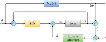
For benchmarking, H-MRAC was compared to MRAC and A-PID. Figure 5 shows the MRAC. The difference between MRAC and H-MRAC is that in the first one the PID controller was removed. Figure 6 shows the A-PID, adaptive PID controller, which is the topological formulation proposed by Zhang and Wei [Reference Zhang and Wei27]. This structure consists of only one adjustment parameter.
Block diagram without PID controller (MRAC).

Block diagram of controller developed by Zhang and Wei [Reference Zhang and Wei27] (A-PID).

3.5. H-MRAC controller design
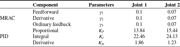
The joint’s control was done in a decentralised way, in which each joint has its H-MRAC. The adaptation gains were tuned following Aström and Wittenmark’s [Reference Aström and Wittenmark31] guidance, using simulations to evaluate the performance metrics for several discrete values in a given interval. Therefore, the values found can be considered suboptimal and with values close to optimum. Table I shows the obtained gains.
Tuning parameters for H-MRAC and PID controllers.

The PID controller was designed in parallel configuration and its parameters were tuned by Ziegler & Nichols’s second method [Reference Ogata43]. Eq. (37) shows the model used.
 \begin{equation} u_c = K_P(\text{ref} - y) + K_I\int(\text{ref} - y)dt + K_D\frac{d}{dt}(\text{ref} - y),\end{equation}
where ref is the control system’s input reference.
The A-PID controller adaptation gain has a value of 1, both for joints 1 and 2, and the gains
 $K_P$
,
 $K_I$
and
 $K_D$
have the same values as H-MRAC.
4. Simulation Results
For system simulations and experiments, it is proposed a position reference
 $\mathbf{{P_1}} = [0.5091 \, \, 0.1488]^T$
m in the manipulator’s end-effector at 10 s. In 20 s, this reference is changed to
 $\mathbf{{P_2}} = [0.5270 \, \, 0.0754]^T$
m and in 30 s the position reference is again
 $\mathbf{{P_1}} = [0.5091 \, \, 0.1488]^T$
m. In all simulations and experiments, a 3.92 N disturbance was applied on the manipulator’s end-effector in 40 s.
The parameters
 $\xi$
and
 $\omega_n$
for each joint were obtained from the BLII methodology ([Reference Bomfim and Lima II41]). In this methodology, a pressure step is applied to each joint and each parameter is obtained from the transient response’s characteristics. With the data obtained in the BLII method and using multiple linear regression, Eqs. (38) and (39) were obtained.
 \begin{equation} Pr_{b,2} = 0.5763 + 6.0279 q_2 + 0.0793\|\mathbf{F_e}\|,\end{equation}
 \begin{equation} Pr_{b,1} = 0.0616 + 13.5700 q_1 + 1.2500 q_2 + 0.2120\|\mathbf{F_e}\|,\end{equation}
where
 $Pr_{b,1}$
e
 $Pr_{b,2}$
are pressures in the antagonist muscles for joints 1 and 2, respectively (bar);
 $q_1$
and
 $ q_2$
are the angles in joints 1 and 2, respectively (rad) and
 $\|\mathbf{F_e}\|$
is the euclidean norm of the end-effector’s load (N).
Using the inverse kinematic model, the Configuration Space to position reference
 $\mathbf{{P_1}}$
can be obtained:
 \begin{equation} \mathbf{q} = [q_1 \, \, q_2]^T = [0.2 \, \, 0.2]^T \text{rad}.\end{equation}
Using Eqs. (38), (39), and (40), the pressure in each actuator can be estimated (Actuator Space):
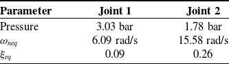
 \begin{equation} \mathbf{Pr_b} = [Pr_{b,1} \, \, Pr_{b,2}]^T = [3.03 \, \, 1.78]^T \text{bar}.\end{equation}
Correlations of 0.98 for joint 2 and 0.96 for joint 1 were obtained with models Eqs. (44) and (47), respectively. Equations (42) and (43) represent the natural frequency and damping coefficient for joint 2 and Eqs. (45) and (46) for joint 1, respectively.
 \begin{equation} \omega_{neq2}=15.6919 - 0.0617 Pr_{b,2} - 0.6908\|\mathbf{F_e}\|,\end{equation}
 \begin{equation} \xi_{eq2} = 0.2669 - 0.0052Pr_{b,2}-0.0038\|\mathbf{F_e}\|,\end{equation}
 \begin{equation} G_2(s)=(0.1600Pr_{b,2}- 0.010\|\mathbf{F_e}\|-0.0700)\left ( \frac{ \omega_{neq2}^2}{s^2 + 2\xi_{eq2} \omega_{neq2}\, s + \omega_{neq2}^2} \right ),\end{equation}
 \begin{equation} \omega_{neq1}=6.7302 - 0.2114 Pr_{b,1} - 0.0816\|\mathbf{F_e}\|,\end{equation}
 \begin{equation} \xi_{eq1} = 0.0963- 0.0017Pr_{b,1}-0.0058\|\mathbf{F_e}\|,\end{equation}
 \begin{equation} G_1(s)=(0.070Pr_{b,1}- {0.02q_2}- 0.020\|\mathbf{F_e}\|+0.0200)\left ( \frac{ \omega_{neq1}^2}{s^2 + 2\xi_{eq1} \omega_{neq1}\, s + \omega_{neq1}^2} \right ).\end{equation}
With the parameters from Table II, it is possible to obtain the linearised models for joints 1 and 2. Equations (48) and (49) represent the transfer functions for joints 2 and 1, respectively. Joint 1 has smaller
 $\xi$
and
 $\omega_n$
, when compared to joint 2. Such phenomenological response is easily elucidated when compared to the pendulum system. When weight and length are increased, its parameters
 $\xi$
and
 $\omega_n$
are reduced.
 \begin{equation} G_2(s)=(0.21) \left ( \frac{242.74 }{s^2+8.10s+242.74} \right ),\end{equation}
 \begin{equation} G_1(s)=(0.23) \left ( \frac{37.09 }{s^2+1.10s+37.09} \right ).\end{equation}
Robotic joint equivalent parameters calculated by BLII methodology [Reference Bomfim and Lima II41].

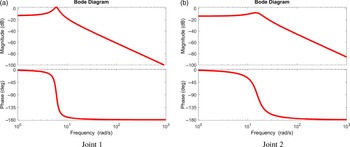
Figure 7 shows the frequency response for joints 1 and 2, obtained from Eqs. (49) to (48), respectively. The frequency response analysis is important because it is necessary to know the mechanism’s maximum operating frequency without lag and attenuation. From Fig. 7(a), it can be seen that at frequencies between 3 and 7 rad/s there is amplification due to resonance phenomenon, and above 7 rad/s there is attenuation of the signal. It was also observed that there is a lag above 1 rad/s. The analysis for Fig. 7(b) can be done in a similar way. Thus, it is recommended that the manipulator does not operate at frequencies above 1 rad/s.
Frequency response for joints 1 and 2.

By the equations, it can be analysed that the addition of load on the manipulator’s end-effector reduces the equivalent natural frequencies of joints 1 and 2. The increase in pressure has the effect of reducing
 $\omega_{neq}$
for joints 1 and 2. For an equivalent damping coefficient (
 $\xi_{eq}$
), the same effect was observed, in which the increase in pressure and load causes its reduction. Similar effects were observed in ref. [Reference Bomfim and Lima II41], in which the increase in load reduced the values of
 $\xi_{eq}$
and
 $\omega_{neq}$
for an 1-DoF manipulator.
The increase in muscle pressure causes a small increase in the actuator stiffness, which added to the increase in mass, causes the damping coefficient to reduce its value. The phenomenon can be explained by Eq. (50), in which the increase in mass and stiffness results in the
 $\xi_{eq}$
reduction.
 \begin{equation} \xi_{eq}=\frac{B_{system}}{B_{critical}} = \frac{B}{\sqrt{4mK}}.\end{equation}
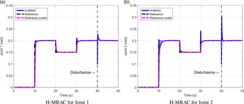
Figure 8 shows the H-MRAC response for joints 1 and 2.
H-MRAC response for joints 1 and 2.

In sequence, H-MRAC is compared to MRAC in order to present the performance improvement in transient regime. Then, H-MRAC is compared to A-PID. The later is a hybrid controller proposed by Zhang and Wei [Reference Zhang and Wei27], in which the topological structure has only one adjustment parameter. Thus, H-MRAC represents an evolution of Zhang and Wei [Reference Zhang and Wei27] proposal.
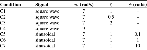
For comparison between H-MRAC, MRAC and A-PID, seven operating conditions were defined in Table III.
Operating conditions for controller performance analysis.

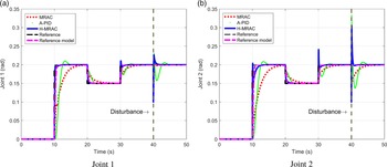
Figure 9 represents a comparative study between H-MRAC, MRAC and A-PID for condition C1. The reference model has a natural frequency of 7 rad/s and the damping coefficient is equal to 1. From Fig. 9, it can be observed that the proposed controller is able to reject disturbances, has faster convergence and is able to track the reference trajectory. It can be analysed that the MRAC alone needs a higher convergence time to adjust the parameters, when compared to the A-PID and H-MRAC, increasing the trajectory tracking error. With PID controller use, the convergence time is reduced from 9.0 to 0.5 s. The A-PID showed greater overshoot and convergence time when compared to H-MRAC.
Comparative study between H-MRAC, MRAC and A-PID for condition C1: position response.

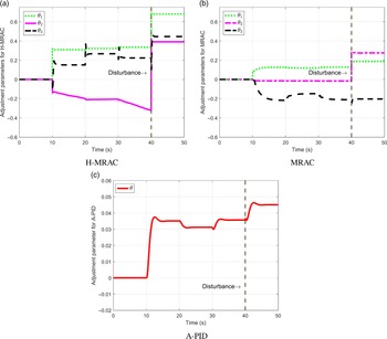
Figure 10 shows the adjustment parameters evolution for each controller.
Adjustment parameters for H-MRAC, MRAC and A-PID for condition C1 for joint 1.

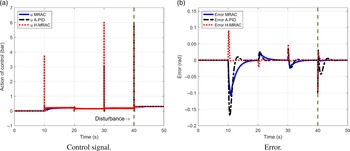
Figure 11(a) shows the control signal from the MRAC, A-PID and H-MRAC controllers for joint 1. From the figure, it can be seen that H-MRAC has a more aggressive control action, especially in reference changes. Thus, H-MRAC has less error in tracking the trajectory, which can be observed in Fig. 11(b).
Comparative study between H-MRAC and MRAC for condition C1, joint 1. (a) Control signal. (b) Error.

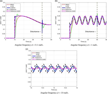
The square wave signal was replaced by a sinusoidal input of amplitude 0.05 rad, angular frequency
 $\phi$
of 0.1, 1 and 10 rad/s and offset of 0.20 rad:
 $\text{ref}(t)= 0.05 \,\text{sin}(\phi t)+0.20 \, \,\text{rad}$
(conditions C5, C6 and C7). The idea is to vary the signal’s frequency and analyse its effect on the response. Results are shown in Fig. 12(a), (b) and (c), respectively. By the figures, it can be analysed that the results were similar to those found previously, in which H-MRAC showed better tracking.
Sinusoidal response for joint 1. (a) Angular frequency
 $\phi=0.1$
rad/s. (b) Angular frequency
 $\phi=1$
rad/s. (c) Angular frequency
 $\phi=10$
rad/s.

According to the Bode diagram shown in Fig. 7, at frequencies above 1 rad/s the input signal will be delayed and attenuated. Figure 12(c) shows these lags and attenuation, validating the analyses performed in Section 4.
4.1. Error analysis in simulations
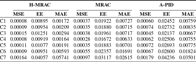
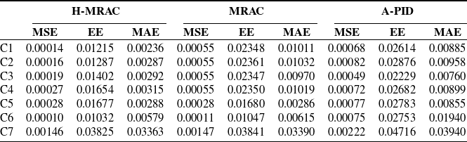
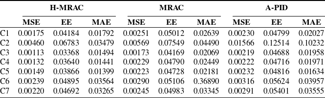
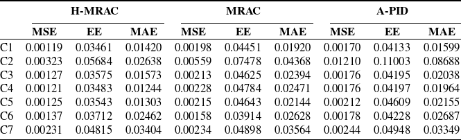
The metric used to measure the divergence between the reference signal and the controller’s responses will be the effective error – EE (rad), mean square error – MSE (rad2;) and mean absolute error – MAE (rad) [Reference Pal44]. Tables IV and V show the errors for joints 1 and 2, respectively. By the tables, it can be observed that for joints 1 and 2, H-MRAC controller presented better results for six of the seven operational conditions: the error was on average 37.69% and 51.01% lower for H-MRAC, when compared to MRAC and A-PID, respectively.
Position error for joint 1 in the simulations.

Position error for joint 2 in the simulations.

5. Experimental Results and Discussion
5.1. Experimental apparatus
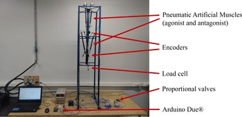
Figure 13 shows the elbow manipulator with its main pneumatic and electronic components. The McKibben muscles in agonist/antagonist configuration drive the articulated joints. The project’s purpose is to emulate the human biceps/triceps behaviour, causing the joint to operate at positive and negative angles [Reference Tonietti and Bicchi45–Reference Yang, Yu and Zhang47].
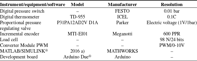
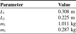
The measurement instruments, equipment and software are shown in Table VI. Table VII shows the manipulator parameters.
Elbow manipulator with its main pneumatic and electronic components.

Measuring instruments, equipment and software used in the research.

Manipulator parameters.

The sensor/actuator interface was developed using an ArduinoDue
 $^{\circledR}$
development board [Reference Yang, Yu and Zhang47–Reference Hao, Yang, Sun, Xiang and Xue49]. The sampling time used was 1 ms, which was sufficiently small, considering that the peak time of the joint response is around 220 ms. In this situation, the joint moves 45 degrees for a pressure input of 5 bar. Considering that the encoder resolution is 600 PPR (pulses per revolution), the required operating frequency is 340.91 Hz, and 1 kHz is large enough for the application.
The control system was developed in Matlab/Simulink
 $^{\circledR}$
. A pulse width modulation (PWM) command signal is sent to a PWM/analogue converter module and a command 0–10 V is sent to the proportional valves. The signals from encoders and load cell are read through digital and analogue input ports, respectively.
5.2. Main experimental results
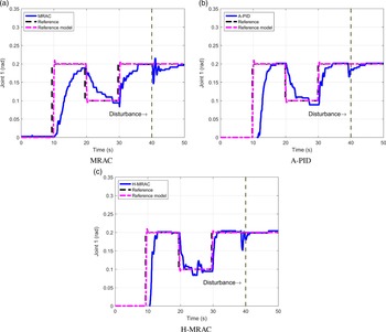
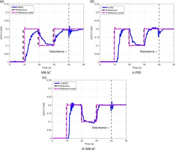
Figures 14 and 15 shows the responses for the MRAC, A-PID and H-MRAC controllers for joints 1 and 2, respectively. It can be seen that the experiments and simulations behaviour was analogous. The H-MRAC showed less tracking error, with MRAC having a longer convergence time.
Joint 1 response.

Joint 2 response.

Comparing simulations and experiments, it can be observed that in the experiments, the errors, in general, are one order of magnitude larger. This is mainly due to the effects of signal discretisation and sensor resolution. For example, the encoder used has 600 PPR. If it were replaced by one with a resolution of 6000 PPR, the errors would drop drastically.
Another point to note is that there were no large comparative variations in the global mean error when H-MRAC is compared with MRAC and A-PID.
5.3. Error analysis in experimental tests
Tables VIII and IX show the error during the experimental tests. The error was on average 37.46% and 30.25% lower for H-MRAC, when compared to MRAC and A-PID, respectively.
Position error for joint 1 in experimental tests.

Position error for joint 2 in experimental tests.

It was observed an error reduction in simulations and experiments when the damping coefficient or the natural frequency are increased in the reference model. The increase in the
 $\xi$
implies a more stable response and the increase in the
 $\omega_n$
implies a shorter rise time and both characteristics facilitate the position tracking.
6. Safe Human–Robot Interaction using ISO/TS 15066
With the increasing demand for humans and robots to collaborate in the same workspace, it is essential that robots react and adapt instantaneously to unforeseen events to ensure safety [Reference Huber and Wollherr50]. In De Santis et al. [Reference De Santis, Siciliano, De Luca and Bicchi51], an atlas was developed on the human–robot physical interaction. Safe physical interaction can be achieved in mechanical design, actuator selection and control architecture design. In the present research, the authors opted to replace electric motors with PAMs. According to Rosenstrauch and Krüger [Reference Rosenstrauch and Krüger52], the ISO/TS 15066 standard defines maximum values for force (140 N), pressure (200 N/cm2) and energy (0.49 J) during the collision, in order to have a safe interaction in collaborative robotics.
For force, the research developed a model in multiple linear regression given by Eq. (51) with coefficient of correlation equal to 0.98. The equation was obtained by varying the collision bulkhead position and the pressure in each muscle.
 \begin{equation} F_{collision} = -1.1466 + 1.4982 Pr_{b,1} + 0.8814 Pr_{b,2} -45.3000 q_1 -4.1800 q_2,\end{equation}
where
 $F_{collision}$
is the end-effector collision force (N).
When
 $Pr_{b,1}=Pr_{b,2}=$
6 bar and
 $q_1=q_2=$
0 rad, the collision force is 7.13 N, reaching its maximum value. The collision contact area is 1 cm2. Thus, the maximum pressure is 7.13 N/cm2.
The maximum velocity is obtained from Eq. (52),
 \begin{equation} v_{mef} = \sqrt{\frac{E_c}{M_m}},\end{equation}
where
 $v_{mef}$
is the maximum end-effector velocity;
 $E_c$
is the collision energy and
 $M_m$
is the manipulator’s mass.
Considering that the mechanism’s mass is 1.798 kg (arm + load) and the maximum collision energy is 0.49 J, the maximum linear velocity of end-effector cannot exceed 0.55 m/s.
Then, the three premises of ISO/TS 15066 will be met and the manipulator will operate safely.
7. Conclusion
The research achieved the objective of developing a new topological approach for the hybrid controller. To the previous approach, A-PID, the derivative and feedforward controllers were added, which improved the performance in the considered error metrics. The comparison with the MRAC showed the importance of using the PID controller and the performance improvement in the transient regime.
The use of Lyapunov’s theory proved to be a powerful tool for the design of H-MRAC, since the stability analysis is embedded in the controller synthesis. Another important feature is that MRAC is model-free, which removes the need for analytical phenomenological models or plant identification. In this way, it was possible to guarantee asymptotic stability for the control system during the design stage and to reduce the design steps.
It is worth mentioning that the robotic manipulator met the ISO/TS 15066 standard, which makes it a potential candidate for collaborative and assistive robotics.
Suggestions for future work are:
-
1. to manufacture the muscle using other polymeric materials, such as the vehicle air chamber, for example;
-
2. to control the mechanism with other advanced control techniques, such as sliding mode controller (SMC), for example;
-
3. to analyse the control technique for manipulators with three or more DoF;
-
4. to use the control technique on exoskeletons, orthoses and prostheses, in which the reference model may come from electromyogram (EMG) or electroencephalogram (EEG) signals;
-
5. to create rehabilitation and surgery equipment, in which the pose control can be used in gradual recovery of patients and/or to assist the surgeon in the movement to be applied to vital organs, for example; and
-
6. to develop collaborative robotic systems in which the operator will occupy the manipulator’s working space.
For more information, see the following videos showing trajectory tracking and collision tests. In the trajectory tracking test video, https://youtu.be/120xuP2Qq-A, the mechanism response for a step change in set-point is presented. In the collision test video, https://youtu.be/pAk-STBwr9o, compliance with the ISO/TS 15066 standard is demonstrated.
Acknowledgements
The authors would like to acknowledge the support of IFMG/Congonhas Hydropneumatics Laboratory during the experiments execution and professor Dimas Abreu Archanjo Dutra for the support in the stability analysis.
Author Contributions
Marcelo Bomfim and Eduardo Lima II wrote the text. Marcelo Bomfim and Neemias Monteiro were responsible for the new topological approach development and for proof of asymptotic stability and orthographic check. Eduardo Lima II is first author’s supervisor.
Financial Support
This research received no specific grant from any funding agency, commercial or not-for-profit sectors.
Conflicts of Interests
None.
A. Necessary and Sufficient Condition for LCF, in Eq. (20), to be Positive Definite Function
The proposed function V is differentiable, and will be equal to zero when
 $e=\dot{e}=0$
and the adjustment parameters converge to their correct values:
 $\beta\theta_1=\beta_m$
,
 $\beta\theta_2=\alpha_{1m}-\alpha_1$
and
 $\beta\theta_3=\alpha_{2m}-\alpha_2$
, that is, the system equilibrium points (EP). Thus, the condition that remains for V to be positive defined is that Eq. (20). is greater than zero out the EP.
The component
 $V_2$
consists of quadratic terms, then,
 $V_2>0$
while the EP (
 $\beta\theta_1=\beta_m$
,
 $\beta\theta_2=\alpha_{1m}-\alpha_1$
and
 $\beta\theta_3=\alpha_{2m}-\alpha_2$
) are not met. On the other hand, the verification of
 $V_1>0$
depends on the parameters
 $\Gamma_1, \Gamma_2$
and
 $\Gamma_3$
.
The terms
 $\Gamma_1 e^2$
and
 $\Gamma_3 \dot{e}^2$
are already greater than zero for
 $e, \dot{e} \in \mathbb{R}^*$
(non-zero real numbers). When e and
 $\dot{e}$
are strictly positive, it is clear that
 $V_1>0$
, because the term
 $2\Gamma_2 e\dot{e}$
will be greater than 0. The same is true when e and
 $\dot {e}$
are strictly negative. Then, it remains only to analyze the situation where e and
 $\dot{e}$
have opposite signals, as follows below.
It is known that,
 \begin{equation} \Gamma_1 e^2 + 2\sqrt{\Gamma_1}\sqrt{\Gamma_3}e\dot{e}+\Gamma_3 \dot{e}^2 = \left ( \sqrt{\Gamma_1}e + \sqrt{\Gamma_3}\dot{e} \right )^2 \geq 0, \quad \text{for}\, e, \dot{e} \in \mathbb{R}^*\end{equation}
So, if a
 $\Gamma_2$
is taken, such as
 $ \sqrt{\Gamma_1}\sqrt{\Gamma_3}>\Gamma_2$
, it is guaranteed that
 $2\Gamma_2 e\dot{e} > 2\sqrt{\Gamma_1}\sqrt{\Gamma_3}e\dot{e}$
for e and
 $\dot{e}$
with opposite signals. That is,
 \begin{equation} V_1=\frac{1}{2} \Biggl (\Gamma_1 e^2 + 2\Gamma_2 e\dot{e} +\Gamma_3 \dot{e}^2\Biggl ) \, >\frac{1}{2} \Biggl ( \Gamma_1 e^2 + 2\sqrt{\Gamma_1}\sqrt{\Gamma_3}e\dot{e}+\Gamma_3 \dot{e}^2 \Biggl ) \geq 0,\end{equation}
for e and
 $\dot{e}$
with opposite signals; and
 $e, \dot{e} \in \mathbb{R}^*$
.
Therefore, it is concluded that if
 $\Gamma_1 \Gamma_3 > \Gamma_2^2$
, the component
 $V_1>0 $
and consequently V will be positive definite.
B.
 $\ddot{e}$
General Equation

The differential equations that describe the plant phenomenological behavior and the control law, present in Eqs. (18) and (16), can be rewritten through:
 \begin{equation} s^2Y +\alpha_1sY+\alpha_2Y = \beta(\theta_1U_c -\theta_2sY-\theta_3Y).\end{equation}
It should be noted that the complex frequency or Laplace domain can be used, since the control law is linear. Solving multiplication for Eq. (B1) and regroup terms, is obtained:
 \begin{equation} s^2Y + (\alpha_1+\beta\theta_2)sY+ (\alpha_2+\beta\theta_3)Y = \beta\theta_1U_c.\end{equation}
Rearranging Eq. (17), Eq. (B3) is obtained.
 \begin{equation} s^2Y_m + \alpha_{1m}sY_m+ \alpha_{2m}Y_m = \beta_m U_c.\end{equation}
Substituting
 $Y_m$
by
 $Y-E$
in Eq. (B3):
 \begin{equation} (s^2 + \alpha_{1m}s + \alpha_{2m})(Y-E) = \beta_m U_c,\end{equation}
 \begin{equation} (s^2 + \alpha_{1m}s + \alpha_{2m})E = s^2Y + (\alpha_{1m}s + \alpha_{2m})Y-\beta_m U_c.\end{equation}
Isolating
 $s^2Y$
in Eq. (B2) and replacing in Eq. (B5):
 \begin{equation} (s^2 + \alpha_{1m}s + \alpha_{2m})E = \beta\theta_1U_c -(\alpha_1+\beta\theta_2)sY- (\alpha_2+\beta\theta_3)Y+ (\alpha_{1m}s + \alpha_{2m})Y-\beta_m U_c.\end{equation}
 \begin{equation} (s^2 + \alpha_{1m}s + \alpha_{2m})E = (\beta\theta_1-\beta_m)U_c- (\beta\theta_3+\alpha_2-\alpha_{2m})Y-(\beta\theta_2+\alpha_1-\alpha_{1m})sY\end{equation}
By passing the Eq. (B7) to the time domain, and rearranging some terms, the general equation of
 $\ddot{e}$
is obtained:
 \begin{equation} \ddot{e}=-\alpha_{1m}\dot{e}-\alpha_{2m}e+(\beta\theta_1-\beta_m)u_c - (\beta\theta_3 + \alpha_2-\alpha_{2m})y -(\beta\theta_2 + \alpha_1-\alpha_{1m})\dot{y} .\end{equation}
C. Relation Analysis between
$\Gamma_1$
,
$\Gamma_2$
and
$\Gamma_3$


To deepen the relation between
 $\Gamma_1$
,
 $\Gamma_2$
and
 $\Gamma_3$
, the derivative of
 $V_1$
is used:
 \begin{equation} \dot{V}_1 = \Gamma_1 e \dot{e} + \Gamma_2\dot{e}^2 + \Gamma_2 e \ddot{e} + \Gamma_3 \dot{e} \ddot{e} = \Gamma_1 e \dot{e} + \Gamma_2\dot{e}^2 + (\Gamma_2 e +\Gamma_3 \dot{e})\ddot{e}.\end{equation}
When the EPs of
 $V_2$
converge, the Eq. (27) is reduced to:
 $ \ddot{e}=-\alpha_{1m}\dot{e}-\alpha_{2m}e$
. Then, substituting
 $\ddot{e}$
in Eq. (C1):
 \begin{equation} \dot{V}_1 = \Gamma_1 e \dot{e} + \Gamma_2\dot{e}^2 + (\Gamma_2 e +\Gamma_3 \dot{e})(-\alpha_{1m}\dot{e}-\alpha_{2m}e).\end{equation}
Solving multiplication and regroup terms, is obtained:
 \begin{equation} \dot{V}_1 = (\Gamma_1 - \Gamma_2\alpha_{1m} -\Gamma_3\alpha_{2m} )e \dot{e}+ (\Gamma_2 -\Gamma_3\alpha_{1m} )\dot{e}^2- \Gamma_2\alpha_{2m} e^2.\end{equation}
For
 $\dot{V}_1 \leq 0$
, the Eqs. (C4) and (C5) must be obeyed. This ensures stability in Lyapunov’s sense.
 \begin{equation} \Gamma_1 - \Gamma_2\alpha_{1m} -\Gamma_3\alpha_{2m} = 0,\end{equation}
 \begin{equation} \Gamma_3\alpha_{1m}> \Gamma_2.\end{equation}
As a result of Eq. (C5), is obtained:
 \begin{equation} \Gamma_3= \frac{\Gamma_2}{\alpha_{1m}} + \delta_1 = \frac{\delta_2}{\alpha_{1m}\alpha_{2m}} + \delta_1 ,\end{equation}
where
 $\delta_1$
and
 $\delta_2=\Gamma_2\alpha_{2m}$
are strictly positive.
Replacing Eq. (C6) in Eq. (C4),
 $\Gamma_1$
can be defined by:
 \begin{equation} \Gamma_1 = \left ( \frac{\alpha_{1m}^2+\alpha_{2m}}{\alpha_{1m}\alpha_{2m}} \right ) \delta_2+ \delta_1 \alpha_{2m}.\end{equation}
Using Eqs. (C6), (C7) and
 $\Gamma_2=\delta_2/\alpha_{2m}$
, can be easily verified, by inspection, that the condition required in the Appendix A,
 $\Gamma_1 \Gamma_3 > \Gamma_2^2$
, is being obeyed.