
I. INTRODUCTION
Liquid Metal Embrittlement (LME) is a special type of environmental effect where an otherwise ductile material has a brittle fracture mode when mechanically tested while in contact with a liquid metal. LME of austenitic steels by liquid sodium (Na) is of relevance for sodium-cooled nuclear power plants or solar thermal power plants using intermediate heat transfer sodium loops. It is therefore a subject of importance related to the structural safety of such structures and it is highly desirable to assess the potential sensitivity to LME. The recent outcome of LME research shows that to obtain a correct sensitivity assessment, great care must be taken to define proper testing conditions that take into account the physico-chemistry of the solid–liquid interface Reference Fazio1 and ensure good surface’s wettability. Reference Hémery, Auger, Courouau and Balbaud-Célérier2 By correct assessment, one implies reproducible results in mechanical properties as well as a quantification of the maximum possible mechanical degradation. Nonobservance of these conditions, particularly the requirement of prewetting, potentially leads to a spread in the degree of measured embrittlement and at the extreme wrong null-results. The requirement of good wetting is crucial in particular to enable the supply of liquid at the crack tip during crack propagation (provided that the systems have a brittle crack initiation).
The earlier analysis of the interaction of austenitic steels with sodium Reference Bhat and Borgstedt3 indicated that a high content of dissolved oxygen favors the formation of a NaCrO2 scale in replacement of the passive chromium oxide that natively forms in air. These exposure conditions were observed to trigger a transition from nonwetting of liquid sodium on the steel’s surface to total wetting by liquid sodium of the corroded layer. Reference Longson and Prescott4 Consequently, in a prior work of ours, Reference Hémery, Auger, Courouau and Balbaud-Célérier5 pre-exposure to oxygenated sodium at the level of 200 µg/g was used to promote wetting of the 304L steel by sodium. Alkali liquid metals such as sodium are particularly demanding in terms of experimental facilities due to their strong reactivity with di-oxygen and water vapor. The corrosion behavior depends largely upon the content of dissolved impurities (oxygen, hydrogen, nitrogen, or carbon). Therefore, a facility with a controlled impurity level allowing handling of sodium in satisfactory conditions was used that simplifies all operations required for preparation of the testing and handling of the liquid metal. Reference Courouau, Balbaud-Célérier, Lorentz and Dufrenoy6
In addition, specific operating procedure and purification step were developed to ensure efficient control of the dissolved oxygen in the liquid sodium to a definite level. The issue of contamination during handling is particularly acute with alkali metals and requires glove boxes with a content of water and oxygen controlled to remain continuously below a level of 1 wppm. A similar facility for mechanical testing has been developed in parallel with transfer under cover gas ability. Reference Hémery, Auger, Courouau and Balbaud-Célérier5 While handling and manipulations require high purity, it can be beneficial to re-introduce oxygen at a controlled level in sodium processes. Indeed, by applying pre-exposure in oxygenated sodium at a controlled level, a drastic change in the wettability of the 304L steel by sodium was observed as expected by prior know-how. Reference Longson and Prescott4 The formation of NaCrO2, supposedly responsible for the observed wettability change, was only inferred from the thermodynamical analysis of our pre-exposure conditions (X-ray diffraction analysis did not convincingly detect this oxide even with a small angle configuration). We report here a dedicated analysis of the interface evolution particularly by transmission electron microscopy (TEM) on the focused ion beam (FIB)-extracted lamella. One of the aims of this study is to provide firm ground for the pre-exposure wetting on an oxide scenario that was proposed earlier. Reference Hémery, Auger, Courouau and Balbaud-Célérier5
The pre-exposure conditions for the wetting transition were also the conditions in which a reproducible onset of brittle cracking of 304L steel was observed when tested in contact with liquid sodium at a low strain rate in the temperature range 573–673 K. Reference Hémery, Auger, Courouau and Balbaud-Célérier5 This case of liquid sodium embrittlement of austenitic stainless steels presents a challenge to fracture analysis due to the complexity of the observed fracture surfaces. Some cracks observed on the fracture surface are clearly intergranular, but the vast majority of the fracture surface does not seem to have a clear interpretation in terms of the crack path relative to the microstructure. The fracture mode is conventionally qualified as the standardized quasi-cleavage mode. The current level of understanding prevents correlating the topographies of the fracture surface as observed by the standard scanning electron microscopy (SEM) surface analysis with microstructural features. A better knowledge of the fracture path would allow a major step forward to pin point the right modeling scheme to tackle this type of environmental fracture. Therefore, to improve the knowledge of this LME fracture type, we characterized the potential relationship between the fracture surface as observed in SEM and the underlying microstructure. Therefore, in the second part of this work, we report a nanoscale TEM analysis on the FIB lamellae extracted from selected areas of the fracture surface that allows us to give a clear interpretation of this otherwise ambiguous LME fracture mode. The implications of this work will be discussed further.
II. MATERIALS AND EXPERIMENTAL PROCEDURE
A. Materials
The chemical composition of the 304L austenitic stainless steel used in this study is listed in Table I. The as-received material was in the annealed and quenched metallurgical state. The reported yield stress was 377 MPa, the ultimate tensile strength was 596 MPa, and the Vickers hardness was 170 HV. The steel is primarily in the austenitic state with 1.8% of δ-ferrite (measurement carried out by ferritoscope). The initial microstructure was analyzed using optical microscopy by electrolytic etching (10% oxalic acid solution) and TEM on a Jeol 1200-EX operated at 120 kV. The mean grain size was estimated to be of the order of 30 µm. TEM analysis of the as-received material indicates a low density of initial dislocations with evidences of stacking faults as expected from a low stacking fault energy steel like the 304L austenitic steel. No initial subgrains structures were found. The sodium used throughout this study is high-purity sodium (>99.95%—ER grade) provided by the Métaux Spéciaux company (Plombière St Marcel, France). Before testing, the sodium was melted and the free level was skimmed off to remove sodium oxides present in excess. A holding step at a temperature of 378 K was then done for ∼300 h, analog to a decantation step, followed by the skimming off any residual oxides present at the free level. Then, a last purification step was achieved at high temperature (∼903 K during 75 h) with a large surface zirconium foil (150 × 300 × 0.125 mm—Neyco, Vanves, France) to gather any residual oxygen. This foil was removed after the purification step. Oxygen was then assessed to be lower than 1 wppm. This was indeed checked with 316L(N) specimens whose oxidation kinetics is known in our conditions. The perfect mirror appearance of the free level qualitatively confirmed this assessment. The resulting total metallic impurity level is less than 10 µg/g (the main impurities are Cl, Fe, and K). The 200 µg/g oxygen condition was obtained by adding, after the zirconium purification step, the required amount of sodium oxide to the liquid metal (Na2O—Alfa Aesar, Haverhill, Massachusetts). After the corrosion test, an additional high-temperature Zr foil purification step is repeated to measure the oxygen content at the end of the test by measuring the weight gain. It was found close to the initial one (200 µg/g).
Composition of the as-received 304L austenitic steel.

B. Experimental procedure
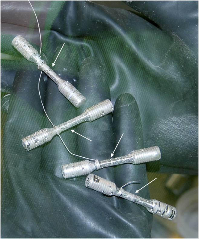
The 304L steel cylindrical notched tensile samples were machined from the transverse-longitudinal direction of the as-received steel’s plate. The uniform gauge length was 20 mm, the diameter was 4 mm, and a notch was machined at the center of the gauge length. The notch depth was set to 600 µm, the tip angle was 60°, and the tip radius was 50 µm. No further polishing was carried out on the machined samples asides being cleaned in acetone in an ultrasonic bath. The samples were brought into an argon (Ar) glove box equipped with an isolated molybdenum crucible located at the bottom but inside of the glove box. Reference Courouau, Balbaud-Célérier, Lorentz and Dufrenoy6 This crucible was filled with the oxygenated sodium. The samples were then dug in liquid oxygenated sodium and remained at 823 K for 250 h for pre-exposure. During corrosion pre-exposure, the system was perfectly tight toward both the atmosphere and the argon of the glove box so that any residual traces of dioxygen and water equilibrate with the liquid sodium. Such contamination is however negligible because of the large volume of liquid sodium compared to the trapped Argon volume. A small plate (∼1 cm2) of mechanically polished 304L steel (SiC P#1200) was added in the bath with the samples as a corrosion coupon. After this pre-exposure step, the samples were taken out of the liquid sodium bath kept at 383 K. The samples were totally covered with a shiny and perfectly wetting film of sodium (see Fig. 1). Most importantly, the notch was fully filled with the sodium’s coating. The solidified sodium stuck in the threading was mechanically removed, and all the samples were brought into the test apparatus under the protection of a double inert gas airtight container.
Image of sodium wetted specimens extracted from the sodium bath after 250 h pre-exposure at 550 °C (sodium wetted notches indicated by arrows).

The mechanical test apparatus consisted of a high-purity Ar glove box connected to a tensile test machine at the crosshead level with a specially designed steel flexible bellow for air insulation and load transmission. The transfer was carried out without exposure of the sample to any contamination from dioxygen or water vapor. The sample to be tested was mounted on the grips of the tensile machine located inside the glove box. The sample heating was carried out by the Joule effect via an internal current loop. The temperature was regulated using a pyrometer. Additional monitoring by a type K thermocouple was used to have a temperature measurement at the notch location. The mechanical tests were performed at a temperature of 573 K and at a crosshead displacement rate of 0.025 mm/min. Because of the notch, the results are not presented as normalized stress–strain curves. Instead, the data analysis is carried out by integrating the mechanical force–displacement curve to obtain the energy to fracture of the test (in Joule). It is then compared with the reference mechanical test obtained at the same temperature and crosshead displacement rate. The reference measurement is carried out with a sample having also been pre-exposed to sodium but later completely cleaned by ethanol washing from any sodium remaining on the surface. This allows us to take into account the possible evolution of the interface, a parameter that might reduce by a small but noticeable amount the energy to fracture of the reference test. Doing so, one avoids overestimating the effect of sodium on mechanical properties, an effect induced by the surface effect at the notch that is particularly sensitive with small-size tensile specimens. In the conditions for this work (temperature of 573 K and a crosshead displacement rate of 0.025 mm/min), the reduction in energy to fracture reads from 20 to 25% depending on the details of brittle crack initiation (several tests were carried out with sodium in these conditions).
After mechanical testing, the test specimen was cleaned in absolute ethanol to dissolve the sodium covering the fracture surface. Within a few minutes exposure, all of the sodium is removed from the fracture surface allowing easy handling in air. One specimen was then cut into pieces to allow for interface analysis. The corroded surface of the corrosion coupon was analyzed on a Ultra 55 SEM (Zeiss, Oberkochen, Germany). A Dual Beam HELIOS Nanolab 650 FIB (FEI, Hillsboro, Oregon) was used to extract TEM lamella using the lift out technique. One TEM foil was extracted, perpendicular to the surface, at a location that was not affected by the plastic deformation near or at the notch (some place along the gauge length but away from the notch). The other ones were extracted from the fracture surface at places representative of the morphology of the fracture surface. First a protective platinum (Pt) layer (of typically 2 µm thickness) was deposited on the surface to protect it from damage during subsequent ion beam sectioning. Two trenches are then milled on both sides of the protected area using a focused Ga+ ion source operated at 30 kV. A U-cut was then made, and the sample was lifted out and attached on a TEM grid by a Pt deposit. A molybdenum grid instead of a copper one was chosen for the lift out devoted to EDX analysis to allow an easier deconvolution of the Na Kα X-ray line (copper has an Lβ line at 949.8 eV while Ga has a Lα line at 1097.9 eV surrounding the Na Kα line at 1041 eV). A low Gallium ion current of 80 pA was used for the final thinning of the lamella to reduce surface artifacts. The TEM lamella was analyzed at 200 kV in an Tecnai F20 TEM (FEI, Hillsboro, Oregon) equipped with an EDX detector. A chemical mapping was carried out on the TEM lamella and treated after background subtraction with a deconvolution algorithm for the sodium Kα X-ray line (EDAX TEAM software, Draper, Utah). The composition profiles of the corroded layers have been assessed semi-quantitatively by Glow Discharge—Optical Electron Spectroscopy (GD-OES) using the Horiba Jobin-Yvon (Kyoto, Japan) GD-Profiler 2 in the radio-frequency mode (30 W & 800 Pa). The emission responses from the excited sputtered elements (O, Fe, Cr, Ni, Mo, C, Si, Mn, etc.) were detected using a polychromator with a focal length of 500 mm, while a monochromator was used to determine the sodium concentration. Reference alloys were used to calibrate the measurements.
To characterize the crack path, two TEM foils were sampled from the brittle fracture surface area of the 304L steel. One lift out was carried out at a location with step ridges on the fracture surface and the other one at a location where an arrested crack was likely to be captured in the foil (see Sec. III.B for further details on the experimental procedure). These areas represented typical morphologies of the quasi-cleavage fracture surface. The crystallographic orientations of the interesting zones in the FIB lamellas were then investigated by a TECNAI F20 (FEI, Hillsboro, Oregon) operating at 200 kV and equipped with the precession automated crystal orientation mapping (ACOM-TEM) using the Astar package. Reference Rauch, Véron, Portillo, Bultreys, Maniette and Nicolopoulos7 Two phases (c.c. and c.f.c.) were allowed in the automated indexing due to the possibility of martensitic transformation of the 304L austenitic steel. A phase map was built whenever necessary.
III. RESULTS
A. Pre-exposure
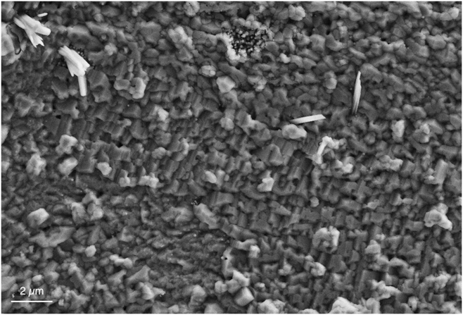
The initial surface of the mechanical test specimen was in the state left by machining i.e., a bright and shiny surface. After exposure to liquid sodium for 250 h at 550 °C with 200 µg/g dissolved oxygen, the surface had a dark aspect indicating that either roughness had developed on the surface or that a compound had formed (sodium was removed by a few minutes immersion in ethanol). The SEM analysis of the surface of the exposed sample is shown in Fig. 2. One can see a continuous coverage of the surface by small crystallites that formed during the immersion in liquid sodium. Therefore, a clear change in the surface phase composition induced by pre-exposure had occurred. Grazing angle X-ray analysis was carried out but did not allow identification of the phase forming this very thin layer.
SEM images of the 304L surface after pre-exposure.

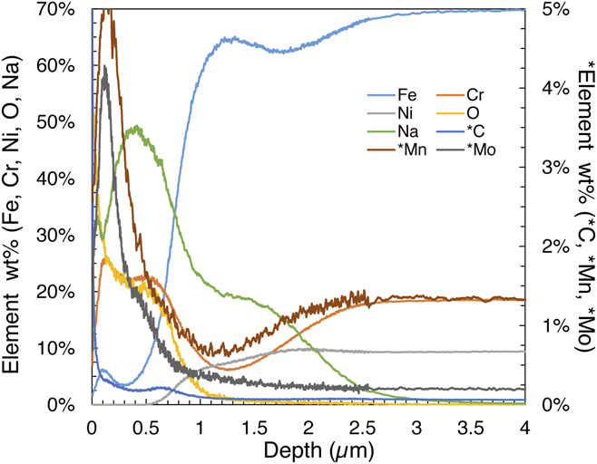
The GD-OES profile carried out on the flat plate introduced with the samples is shown in Fig. 3. At the surface (at the left side of the graph), one notices a drop in the steel’s iron and nickel constituents correlated with a plateau in chromium, oxygen, and sodium. Other minor elements (carbon and molybdenum) have a peak concentration at the extreme surface potentially indicative of mass transfer between the liquid, the molybdenum crucible, and the steel during pre-exposure. The increase in manganese could be explained by the formation of NaMnO2 since it is possible at a high temperature above 80 wppm oxygen. Reference Bhat and Borgstedt3 One notices a secondary peak for sodium between 1 and 1.5 µm depth.
GD-OES profile of sodium-exposed 304L’s surface.

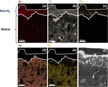
The nanoscale-resolved chemical mapping performed on the TEM lift out is shown in Fig. 4. It indicates that a layer composed mainly of sodium, chromium, and oxygen elements is clearly separated from the underlying matrix elements (iron, chromium, and nickel). The thickness of that layer is of the order of one hundred nm, and the steel/oxide interface is rough. One can note as well that chromium-rich particles formed below the outer NaCrO2. This constitutes an unambiguous evidence of the formation of a continuous layer of this phase over a short-term exposure time in oxygenated sodium. This is the key to explain the role of dissolved oxygen on the wettability of sodium over 304L’s steel.
(a–e) EDX mapping of main elements (f) TEM BF micrograph of the area (the rectangle indicates the area of EDX mapping).

Immediately, underneath this oxide layer, a Cr-depleted zone is found which is certainly caused by the oxidation reaction. The TEM bright field (BF) image of the interface is shown in Fig. 4(f). This corrosion zone presents intergranular pores that are clearly seen on the TEM foil. These porosities were probably filled with liquid sodium so that it explains the secondary sodium peak on the GD-OES profile. The preferential dissolution of iron along the grain boundaries could be the result of the formation of soluble Na4FeO3.
The interface is constituted of small grains of a few hundred nm with holes in between at over a depth of several µm. The microstructure at the surface therefore evolved remarkably from a large grain size to small grains in the machining-affected area. This finding bears similitude with the early finding of Moberly et al. of intergranular precipitates forming during the contact with liquid sodium in the 304L steel. Reference Moberly, Barlow, Garrison and Planting8 The corroded area below the oxide layer is then porous and not protective. One can note that this constitutes a posteriori justification for taking the reference measurement from a batch of sodium-exposed samples since the corrosion-affected area develops some voids that weaken the surface layer.
B. Crack path
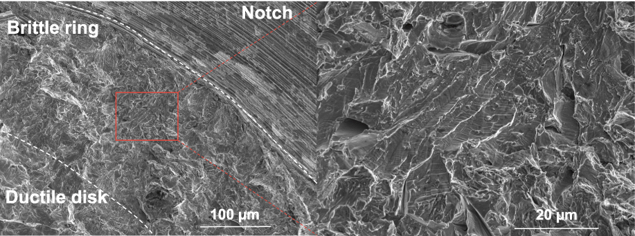
The SEM analysis of the fracture surface is shown in Fig. 5. A brittle ring of 200–300 µm starting at the notch is visible, while the final fracture formed a ductile central ring. Therefore, the fracture surface has a mixed brittle/ductile character that can be explained by the strain rate acceleration at the center during final cracking. A higher magnification view of the fracture surface in the brittle area reveals that some clear intergranular cracks occurred, but the majority of the fracture surface is covered with a quasi-cleavage type fracture surface and numerous step ridges. This is the type of fracture surface that we aimed at investigating further.
Fracture surface analysis after tensile test in sodium at 573 K for 304L.

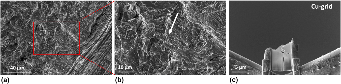
The standard lift out procedure is applied here on carefully selected areas of the fracture surface. The sites were chosen to allow for a potential analysis of the microstructure lying underneath specific features of the fracture surface. The TEM foil 1 was extracted to look for an explanation of the numerous step ridges that are seen on the fracture surface. Arrested cracks were also looked for to analyze the crack path by preserving its crack tip. It was selected looking for cracks seemingly going in the material’s bulk that might have a chance to be short cracks fully captured within the thinned area of the TEM lamella. Such a case is presented here in the TEM foil 2. Figure 6 shows the fracture surface from the FIB preparation of that TEM lamella.
Steps of TEM thin foil 2 preparation using FIB: (a, b) choice of the site of interest (arrow) (c) transfer of the thin foil to the Cu-grid and thinning.

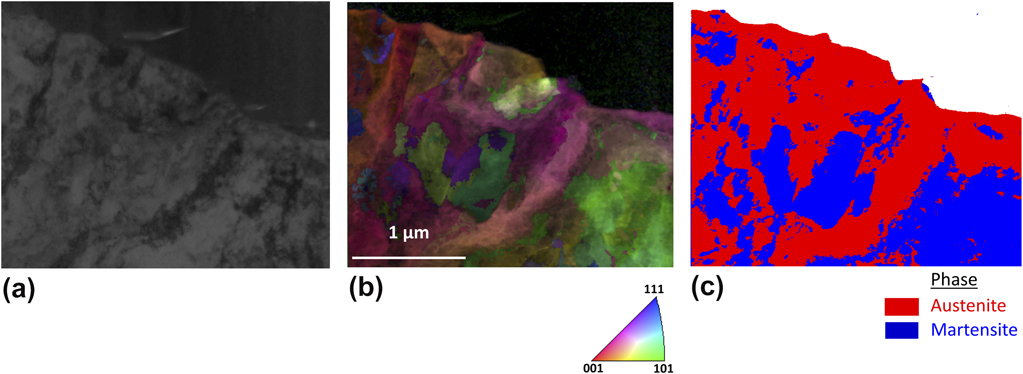
The microstructures indexed by the ACOM-TEM tool of foil 1 and foil 2 are shown in Figs. 7 and 8. The thin foil 1 analysis detected numerous areas with α′ (bcc) phase transition underneath the fracture surface [Fig. 7(c)]. At the same time, twinning and grain refinement was induced by plastic deformation prior to cracking creating a wealth of newly formed interfaces. One can note the clear correlation between the presence of step ridges at the fracture surface [top part of the orientation map in Fig. 7(b)] and large abrupt orientation changes just below the surface ridges. This indicates that the step ridges visible on the fracture surface are a legacy of the deformed microstructure lying below. Indeed, the ridges are correlated with newly formed large grains transverse misorientations or eventually mechanical twin boundaries.
Microstructure beneath the fracture surface in thin foil 1: (a) TEM BF micrograph (b, c) corresponding orientation map superposed with image quality (IQ) with respect to the normal direction and phase mapping.

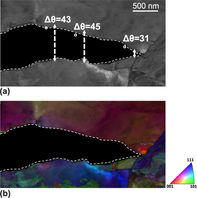
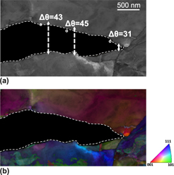
Microstructure beneath the fracture surface in thin foil 2: (a) The TEM BF micrograph and (b) The corresponding orientation map superposed with IQ with respect to the normal direction (the detected phase is entirely austenitic).

An arrested crack was captured in the TEM foil 2 and subsequently indexed (see Fig. 8). The crack has an opening angle of roughly 20°. The crack is clearly intergranular in the γ matrix and was stopped at an interface (a twin boundary) that was slanted toward the presumed vertical loading axis (therefore not oriented favorably for crack propagation). Several measurements of the misorientation across the cracked interface show that the interface belongs to the general type, the one with a misorientation higher than 15° (not corrected for the crack opening angle). The rapid variation of orientations above and below the cracked interface also indicates highly inhomogeneous plastic deformation. The crack stopped at a twin boundary oriented diagonally but did not go further by a cleavage process. The crack path in this case is fully γ/γ interfacial.
IV. DISCUSSION
Austenitic steels such as the 304L spontaneously develop a passive layer with a thickness of few nanometers. It is known that this passive oxide layer has a duplex structure composed of an inner chromium oxide layer (Cr2O3) and an outer layer composed of a mix of iron oxides and hydroxides (Fe3O4, Fe2O3, Fe(OH)2, and FeOOH). Reference Lorang, da Cunha Belo, Simões and Ferreira9 Liquid sodium does not spontaneously wet such a passive layer unless the temperature is raised above a threshold temperature (773 K for at a least a few hours in Ref. Reference Hodkin and Nicholas10). The analysis of the interfacial layer built up during sodium pre-exposure gave the unambiguous outcome that being exposed to oxygenated sodium leads to the formation of a thin NaCrO2-type oxide fully covering the 304L stainless steel surface. Chromium is leached from the 304L steel to form this stable oxide as evidenced by the Cr depletion behind this layer seen in GD-OES and in the EDX mapping of the TEM foil. The threshold level of dissolved oxygen in sodium for the formation of binary oxides (Cr2O3 or FeO) is very high and exceeds its solubility in sodium. Reference Bhat and Borgstedt3 Therefore, the initial passive layer is thermodynamically unstable at a dissolved oxygen content of 200 µg/g and at a temperature of 823 K. On the other hand, the formation of sodium chromite ternary oxide (NaCrO2) is known to be thermodynamically favored in such conditions. Reference Bhat and Borgstedt3 Therefore, the layer found in this study is in agreement with the thermodynamics of the steel in sodium. The relatively small thickness of the layer explains the difficulty when trying to detect it by X-ray diffraction. One notes that the NaCrO2-type oxide has a layered rock-salt structure. Sodium is intercalated between planes formed of chains of CrO and it can be nonstoechiometric while keeping its structure (R-3m). Reference Braconnier, Delmas and Hagenmuller11 As a matter of fact, one should rather consider an oxide of type Na x CrO2 with theoretically x ≤ 1.
The kinetics of formation of this oxide has been studied at low oxygen dissolved content (1–24 ppm) on 316L steel. Reference Cavell and Nicholas12 The kinetics is rather slow with the onset of oxidation starting above grain boundaries then fully covering the remainder of intragranular areas with an assumed diffusion limited parabolic time dependence. This slow growth (limited by the diffusion of chromium) and the fact that the grown layer has a thickness of the order of one hundred nanometers imply that our conditions (200 µg/g, 823 K during 250 h) are almost optimal in building up a compact and fully covering oxide as the inspection by SEM could confirm. Since the wettability has transitioned from initially non-wetting to total wetting, one can infer that sodium wets the Na x CrO2 oxide layer. The very reproducible wetting condition is due to the fact that the Na x CrO2 oxide layer is continuous without interruption. This validates, a posteriori, the pre-exposure conditions that were used in Ref. Reference Hémery, Auger, Courouau and Balbaud-Célérier5 to enhance the wettability of the steel in sodium. These conditions are able to promote the build up of an interfacial ternary oxide whose wettability warrants good and reproducible LME sensitivity studies.
One can elaborate on why sodium totally wets Na x CrO2 while the initial 304L passive oxide is not wetted. Because there is an interfacial phase formation, this wetting transition should belong to the reactive wetting category (liquid metal/oxide reactive wetting). However, the observed transition to a nearly perfect wetting indicates larger improvement than usually reported in reactive wetting. This possibly could imply that the sodium bonding of this new phase is bonded metallically rather than iono-covalently as categorized by Eustathopoulos. Reference Eustathopoulos and Drevet13 It remains to be clarified at this point such that wettability studies of different oxides by liquid sodium would be necessary.
Early on, it was shown that the 304L steel interacted with sodium by the formation of an intergranular phase. Reference Moberly, Barlow, Garrison and Planting8 Here, it is found that the first few microns of the corroded layer develop some porosity and Cr-rich precipitates (see BF TEM image in Fig. 4). This might also be an ingredient favoring early crack initiation. Within a wetted crack, the capillary flow of sodium induced by good wetting is then the key to supply liquid sodium at the crack tip at the earliest stage of LME in a self-maintained process. Once started, a crack is filled and will remain filled as it propagates.
The pre-exposure conditions of this study imply that the sodium that fills the notch of the test specimen is oxygenated at some level (but not necessarily as much as the initial oxygen content if some oxygen was consumed by corrosion in the course of the crack propagation). The effect of dissolved oxygen on the fatigue crack growth rate has been studied between 1 ppm up to 40 ppm with the 304L austenitic steel. Reference James and Knecht14 In the conditions of that study (high test frequency and the lowest temperature starting at 700 K), it was concluded that the dissolved oxygen level did not affect the crack growth rate. In another study, the oxygen influence on crack growth under constant load was studied with the 304L austenitic steel. It was also shown that while varying the oxygen content of sodium from 0.7 to 14 ppm, the intergranular crack growth had only a slight increase and so was deemed largely independent upon the dissolved oxygen concentration. Reference Abe and Shimoyashiki15 It is therefore anticipated that the oxygenated condition is no more detrimental than ultrapure sodium.
The brittle fracture mode evidenced by 304L in contact with oxygenated sodium above 573 K, albeit with limited mechanical degradation (20–25% reduction of the energy to fracture), has possibly important implications. It therefore deserves some close attention. The fracture surface has the typical appearance of the quasi-cleavage brittle fracture with a few intergranular cracking spots. The knowledge of the crack path relative to the microstructure, or at least its categorization in terms of intergranular or intragranular, is decisive for the subsequent understanding and modeling of LME. The crack path was analyzed in typical areas of the fracture surface where the fracture mode is not seemingly intergranular. The fracture surface of this LME case has numerous areas with regular step ridges and buried cracks. Two TEM foils were extracted to analyze the microstructure below regular step ridges and at a location with a microcrack going inside the material. Two main conclusions can be drawn from the analysis that was carried out via the ACOM-TEM technique.
Firstly, the 304L steel microstructure is heavily deformed with a large amount of α′ phase transformed material. Twinning at the microscale is also observed right below the fracture surface. These processes created a microstructural refinement with a large increase in the density of sub-grain boundaries. The step ridges structure is correlated with a large underlying orientation change (subgrains or twin boundaries) and is the trace of the interplay of twinning or phase transform and fracture.
Secondly, the arrested crack of foil 2 shows a typical case of γ/γ interfacial fracture. The underlying microstructure is extremely complex with numerous twins and subgrain boundaries. The fracture surface in the analyzed area was typical of the quasi-cleavage-like fracture area. We can infer that a large part of the crack propagation proceeds as an interfacial fracture.
There are several possibilities to analyze the interplay between fracture and twinning or α′ (bcc) phase transform. Under stress, interface formation via twinning or phase transformation may simply be an independent response over brittle cracking. Another possibility is that the crack may nucleate twins or trigger phase change due to the high stress triaxiality near the crack tip. The third possibility is that these newly formed interfaces may provide a preferred path for the growth of cracks.
In studies of the ductile fracture of the 304LN stainless steel, a clear correlation between deformation induced martensite and the nucleation of microvoids has been found. Reference Das and Tarafder16 In a detailed study of the deformation at room temperature, examples of shear-band intersection, shear-band grain boundary intersection or grain boundary triple point have been found as nucleation sites. Reference Das and Tarafder16 Therefore, the location of α′ (bcc) phase transform or twinning can be found inhomogeneously but everywhere in the microstructure beyond some threshold strain level so that the interface nucleation process takes place at relatively low deformation levels. LME occurs clearly at a later stage of plastic deformation in our case such that a large quantity of interfaces must already be present so that one may think of twinning or phase change as an independent process relative to brittle cracking. It means that it is likely not while twinning that cracking takes place.
We infer that the crack propagation was likely to proceed in a discontinuous manner associated with crack propagation along twinned and γ (fcc) to α′ (bcc) boundaries induced by phase transform. The step ridges of the fracture surface in particular are leftovers of this process. This is similar to the association of twinning and fracture in bcc metals where twin-matrix interfaces are found to be the preferred propagation path. Reference Reid17 The specificity of LME is that here sodium induces crack propagation along newly formed interfaces.
These characterizations document further the LME case of 304L in contact with sodium as being due to the embrittlement of plastically generated interfaces. We highlight the similarity of these findings with the demonstration of the importance of subgrain defect structures in understanding hydrogen embrittlement of steels. Reference Martin, Fenske, Liu, Sofronis and Robertson18 Additional insight calls for in situ investigation of the propagation of a crack induced by liquid sodium. This would provide further indications into the details of the intertwining of phase transform and cracking in austenitic steel’s LME.
V. CONCLUSION
The LME case of the 304L austenitic steel has been analyzed down to the nanoscale in two crucial points. The first one is the wettability and the role of pre-exposure in oxygenated sodium. The second one is related to the correlation of the crack path with the deformed microstructure. The main findings are the followings:
-
(1) The wettability is enhanced due to the formation of a Na x CrO2 (x ≤ 1) layer in direct contact with liquid sodium. The oxygenated sodium pre-exposure conditions that were used allow for the in situ buildup of this oxide and validate the wetting of an oxide scenario that was inferred from the thermodynamical analysis in Ref. Reference Hémery, Auger, Courouau and Balbaud-Célérier5.
-
(2) A quasi-cleavage-like fracture surface with step ridges is to be understood as a product of microstructural changes (phase transform and grain refinement) induced by prior plastic deformation. The step ridges are the markers of discontinuous crack propagation intertwined with phase transform. This strongly hints at the quasi-cleavage being essentially an interfacial cracking in the case of LME of austenitic steels.
-
(3) The crack path was characterized on arrested cracks. It is found fully interfacial. The crack path is found to follow the newly formed interfaces created by plastic deformation prior to cracking that are embrittled by sodium.
We highlight the need to characterize fracture surfaces with the underlying material’s microstructure when assessing the fracture mode of unstable steels like the 304L austenitic steel.
ACKNOWLEDGMENTS
Financial support for this work by the CEA-Generation 4/Structural material project is acknowledged. Exposure of the specimen to liquid sodium was carried out in the Corrona-1 test bench with the help of V. Lorentz (CEA Saclay). The FIB work was carried out using the equipment of the MATMECA consortium partially funded by the ANR under contract number ANR-10-EQUIPEX-37. M. Tabarant (CEA Saclay) is thanked for performing the GD-OES analysis.