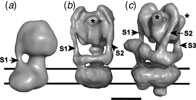
1. Introduction
The link between membrane electrochemical potential and the synthesis (or hydrolysis) of ATP was encapsulated nearly half a century ago in Mitchell's Chemiosmotic Theory, central to which is the function of a reversible ‘ATP synthase’ integrated into the bioenergetic membrane (Mitchell, Reference Mitchell1961). This complex, the F1Fo-ATPase (or F-ATPase for short) uses the transmembrane movement of protons (or, in some cases, Na+), driven by the electrochemical membrane potential, the proton motive force (PMF) to energise the endothermic phosphorylation of ADP. We now know that this energy conversion is catalysed by the F-ATPase operating as a nano-scale machine with a rotary action (Duncan et al. Reference Duncan, Bulygin, Zhou, Hutcheon and Cross1995; Kinosita et al. Reference Kinosita, Yasuda, Noji, Ishiwata and Yoshida1998; Noji et al. Reference Noji, Yasuda, Yoshida and Kinosita1997; Sabbert et al. Reference Sabbert, Engelbrecht and Junge1996). The F-ATPase belongs to a small family of membrane complexes that originated from a common evolutionary ancestor (Grüber et al. Reference Grüber, Wieczorek, Harvey and Müller2001b; Yoshida et al. Reference Yoshida, Muneyuki and Hisabori2001) that includes the vacuolar H+-translocating V1Vo-ATPase (V-ATPase) and A1Ao-ATPase (A-ATPase). In vivo, the V-ATPase operates as an ATP-powered ion pump, whereas the A-ATPases are ATP synthases in the archaea and some bacteria (Forgac, Reference Forgac2007; Müller & Grüber, Reference Müller and Grüber2003). These rotary motors are mechanical marvels, running at speeds in excess of 100 revolutions per minute, generating torque of ~50 pN·nm (on a molecular scale, an enormous force) and performing energy transformation processes at close to 100% efficiency. Although crystal structures have revealed much about the organisation and connectivity of components of these rotary motors, complete atomic resolution models are not yet available. This limits understanding of the mechanism linking transmembrane ion movement to rotational movement. However, recent three-dimensional (3D) reconstructions from electron microscopy (EM) have provided new insights into the architecture of the rotary ATPases. This review explores current knowledge about rotary ATPase structure, mechanism and regulation. In particular, we highlight differences that have now emerged between the rotary ATPases that probably impact on the way they operate as molecular motors.
2. Physiological roles of the rotary ATPases
The F-ATPase is reversible, capable of operating either as an ATP synthase powered by the electrochemical membrane potential, or as an ATP-driven ion pump. Under aerobic conditions in mitochondria it operates in synthase mode, but a decrease in membrane potential under anaerobic conditions can cause it to operate in reverse mode, hydrolysing ATP in order to re-establish the membrane potential. The associated drop in matrix pH to <6·5 promotes binding of a natural inhibitor protein IF1 that blocks the catalytic cycle (Cabezón et al. Reference Cabezón, Montgomery, Leslie and Walker2003; Campanella et al. Reference Campanella, Parker, Tan, Hall and Duchen2009; Pullman & Monroy, Reference Pullman and Monroy1963). A similar ATP synthase operates in the thylakoid membranes of chloroplasts (the CF1Fo-ATPase), energised by a PMF with only a proton gradient (ΔpH) component. In prokaryotes, formation of a membrane potential by aerobic respiration supports ATP synthesis by the F-ATPase as it does in mitochondria. Under conditions where ATP is produced by substrate-level phosphorylation, the bacterial F-ATPase can reverse to pump protons. In this mode, it extrudes ions from the cell to support a PMF and contribute to maintenance of cytoplasmic pH. Bacterial F-ATPases can also be Na+-powered, for example in Propionigenium modestum where a Na+-linked methylmalonyl-CoA decarboxylase establishes the necessary primary Na+ potential (Dimroth et al. Reference Dimroth, Von Ballmoos and Meier2006; von Ballmoos et al. Reference Von Ballmoos, Cook and Dimroth2008). A Na+-specific F-ATPase also operates in Acetobacterium woodii, exploiting the primary Na+ potential set up by its Na+-translocating ferredoxin:NAD+ oxidoreductase (Biegel & Müller, Reference Biegel and Müller2010).
Although the V-ATPase may synthesise ATP in vitro (Hirata et al. Reference Hirata, Nakamura, Omote, Wada and Futai2000), its role in eukaryotes appears to be exclusively as a proton pump. V-ATPases associated with vacuolar compartments of fungi and plants maintain low pH and energise secondary active transport. In higher eukaryotes, the V-ATPase maintains the acidic pH of compartments such as clathrin-coated vesicles, early and late endosomes and lysosomes, and energises solute uptake into secretory vesicles (Forgac, Reference Forgac2007; Marshansky & Futai, Reference Marshansky and Futai2008; Morel, Reference Morel2003). In general, V-ATPase activity can maintain ~100-fold difference in proton concentration between the cytosol and intracellular compartment. However, substantially greater differences are maintained in some systems such as citrus fruit cells. The free energy input from ATP into proton transport by the V-ATPase (a function of the cytosolic ATP/ADP/inorganic phosphate ratio) is essentially fixed, but the energy per transported proton varies with the magnitude of the pH gradient against which it is being pumped. Consequently, the lower the pH of the compartment into which the proton is being transported, the smaller the number of protons that can be transported per catalytic cycle of the V-ATPase. This is analogous to the motor operating in different gears: low gear (expressed functionally as a low H+/ATP ratio) allows proton transport even into compartments with internal pH as low as pH 2–3. The plant tonoplast V-ATPase exhibits a H+/ATP ratio that varies with the pH of the cytoplasm and tonoplast lumen (Davies et al. Reference Davies, Hunt and Sanders1994), implying a pH-sensing function that has also been proposed for at least one mammalian V-ATPase isoform (discussed in Marshansky & Futai, Reference Marshansky and Futai2008). Alternatively, H+/ATP ratios could be controlled by varying the stoichiometry of membrane subunits responsible for proton translocation (discussed in Section 3).
V-ATPases are not exclusively endomembrane proteins, being also found in the plasma membranes of many polarised cells (Wieczorek et al. Reference Wieczorek, Brown, Grinstein, Ehrenfeld and Harvey1999). Hence, for instance, regulated translocation of the V-ATPase to the apical membranes of epididymal clear cells results in a drop in pH in the lumen of the reproductive tract, a crucial step in sperm maturation and activation (Breton et al. Reference Breton, Smith, Lui and Brown1996). A second example is the plasma membrane V-ATPase from the lepidopteran larval midgut that energises secondary active transport processes as well as the alkalinisation of the gut lumen up to a pH of 12 (Wieczorek et al. Reference Wieczorek, Putzenlechner, Zeiske and Klein1991). Almost all mammalian V-ATPase subunits exist as two or more isoforms that display tissue-specific expression or differential membrane targeting (Lee et al. Reference Lee, Li, Ryu, Rhim and Ahnn2010b; Toei et al. Reference Toei, Saum and Forgac2010). These play key roles in, for example, renal function (Brown et al. Reference Brown, Paunescu, Breton and Marshansky2009; Wagner et al. Reference Wagner, Finberg, Breton, Marshansky, Brown and Geibel2004), with mutations leading to renal tubular acidosis (Smith et al. Reference Smith, Skaug, Choate, Nayir, Bakkaloglu, Ozen, Hulton, Sanjad, Al-Sabban, Lifton, Scherer and Karet2000). Naturally occurring V-ATPase mutations also cause osteopetrosis (Frattini et al. Reference Frattini, Orchard, Sobacchi, Giliani, Abinun, Mattsson, Keeling, Andersson, Wallbrandt, Zecca, Notarangelo, Vezzoni and Villa2000; Li et al. Reference Li, Chen, Liang, Li and Stashenko1999) because affected osteoclasts are unable to perform the acid extrusion required for bone resorption (Blair et al. Reference Blair, Teitelbaum, Ghiselli and Gluck1989; Väänänen et al. Reference Väänänen, Zhao, Mulari and Halleen2000). There is also evidence that differential expression of V-ATPase isoforms at the surface of cultured tumour cells correlates with cell invasiveness, linking it to metastatic potential in cancer (Hinton et al. Reference Hinton, Sennoune, Bond, Fang, Reuveni, Sahagian, Jay, Martinez-Zaguilan and Forgac2009; Sennoune et al. Reference Sennoune, Bakunts, Martinez, Chua-Tuan, Kebir, Attaya and Martinez-Zaguilan2004; Sennoune & Martinez-Zaguilan, Reference Sennoune and Martinez-Zaguilan2007).
In archaea, A-ATPases can act as ATP synthases (reviewed in Müller & Grüber, Reference Müller and Grüber2003), with either H+ (e.g. Sulfolobus and Methanosarcina species; Hochstein & Stan-Lotter, Reference Hochstein and Stan-Lotter1992; Inatomi, Reference Inatomi1986; Pisa et al. Reference Pisa, Weidner, Maischak, Kavermann and Müller2007b) or Na+ (e.g. Pyrococcus species; Coskun et al. Reference Coskun, Chaban, Lingl, Müller, Keegstra, Boekema and Grüber2004; Lingl et al. Reference Lingl, Huber, Stetter, Mayer, Kellermann and Müller2003; Pisa et al. Reference Pisa, Huber, Thom and Müller2007a) as the coupling ion. In archaeal species suggested to be primarily fermentative, the A-ATPase may operate as an ion pump. Some bacteria also have A-ATPases, and these enzymes have sometimes been referred to as ‘bacterial V-ATPases’ or ‘V/A-ATPases’ (Hilario & Gogarten, Reference Hilario and Gogarten1998). Sequence similarity, subunit composition and organisation confirm that these are much closer to the archaeal examples than to eukaryotic V-ATPases (Bernal & Stock, Reference Bernal and Stock2004; Mulkidjanian et al. Reference Mulkidjanian, Galperin, Makarova, Wolf and Koonin2008; Müller & Grüber, Reference Müller and Grüber2003); these aspects are discussed in detail below. In Thermus thermophilus, this type of ATPase operates predominantly as a H+-driven ATP synthase (Nakano et al. Reference Nakano, Imamura, Toei, Tamakoshi, Yoshida and Yokoyama2008; Yokoyama et al. Reference Yokoyama, Akabane, Ishii and Yoshida1994), while in Gram-positive bacteria, such as the enterococci and clostridia, they function as Na+ pumps (Boekema et al. Reference Boekema, van Breemen, Brisson, Ubbink-Kok, Konings and Lolkema1999; Kakinuma et al. Reference Kakinuma, Yamato and Murata1999; Speelmans et al. Reference Speelmans, Poolman, Abee and Konings1993). Enterococcus hirae assembles both A- and F-ATPases in the same membrane (Takase et al. Reference Takase, Yamato and Kakinuma1993) and, to date, three species of archaea have been shown to carry genes for both enzymes (Müller & Grüber, Reference Müller and Grüber2003; Sumi et al. Reference Sumi, Sato, Denda, Date and Yoshida1992), although expression of F-ATPase polypeptides has not been observed. The presence of genes for both types of rotary ATPase in the same species is most likely to have arisen through horizontal gene transfer, rather than parallel evolution from a common ancestral complex (Hilario & Gogarten, Reference Hilario and Gogarten1998; Mulkidjanian et al. Reference Mulkidjanian, Makarova, Galperin and Koonin2007). Overall, the distinction between A-ATPases and ‘bacterial V-ATPases’ is blurred, reflecting the difficulties in discriminating between the enzymes solely on the basis of the cell where they occur. The classification here is based on subunit organisation rather than physiological function or occurrence in a particular organism. For consistency, we refer to all bacterial ATPases of the A/V-type as A-ATPase, reserving the term V-ATPase exclusively for the eukaryotic protein, as suggested in (Müller & Grüber, Reference Müller and Grüber2003). Our reasoning is based on the similarities in organisation between the archaeal/bacterial complexes and their divergence from the eukaryotic V-ATPase, which is the main focus of this review.
3. Domain organisation and subunit composition
3.1 Rotary ATPase domains contain separate motor functions
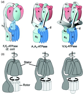
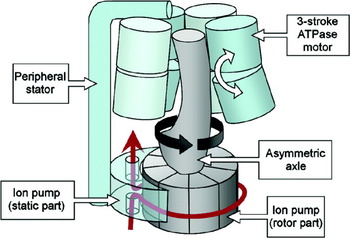
Despite the diversity of function, all rotary ATPases share many basic similarities. Each comprises a soluble ATP synthesising/hydrolysing domain, designated F1, V1 or A1, coupled to a membrane domain (termed Fo, Vo or Ao) that facilitates ion translocation across the membrane (Fig. 1). Each domain is essentially an independent rotary stepper motor, although the actions of these are tightly coupled and co-operative to produce a highly efficient energy conversion machine. The modular nature of the rotary ATPases is underlined by the observation that F1 and A1 domains detached from the membrane retain ATP-driven rotary movement (Imamura et al. Reference Imamura, Nakano, Noji, Muneyuki, Ohkuma, Yoshida and Yokoyama2003; Noji et al. Reference Noji, Yasuda, Yoshida and Kinosita1997), and that F1 domains from H+- and Na+-specific F-ATPases are to some extent interchangeable without loss of function (Laubinger et al. Reference Laubinger, Deckers-Hebestreit, Altendorf and Dimroth1990). In ion pump mode, the three active sites in the soluble domain (effectively a ‘three stroke motor’) sequentially drive rotation of an axle that transmits energy to the membrane domain ion pump. This pump also comprises rotary and static parts, the relative movement of which is the crucial factor in transmembrane movement of ions. The static part is fixed to the soluble domain motor by means of a stator, preventing it from simply following the movement of the axle. ATP synthesis in the F- and A-ATPases requires the system to be powered in reverse mode, with ion movement through the membrane domain driving axle rotation. This motion is translated into sequential conformational changes in the three active sites of the soluble domain, resulting in a cycle of substrate binding, ATP synthesis, and its release. These processes are discussed below. It is worth pointing out that although the rotary ATPases are readily described in terms applied to macroscopic motors, there are limits to the analogy; the molecular motors are fundamentally different, being subject to (and dependent on) thermally driven atomic and molecular scale fluctuations (outlined in Section 4).
Organisation of subunits in rotary ATPases. (a) Subunit arrangements of (αβ)3:γ:ε:c-ring in the F-ATPase, and (AB)3:D:F, E:G and c-ring in the A- and V-ATPases are informed by crystal structures. Other contacts are consistent with cross-linking and interaction data. Overall architecture is surmised from 3D reconstructions by EM. When viewing the external surface in this orientation, catalytic sites are at the α/β and B/A subunit interfaces where α/B is to the left of the subunit pair. In the F-ATPase, the upper part of the peripheral stalk region of the stator is aligned with a non-catalytic β-α interface. Segments a N and a C, respectively, correspond to the cytoplasmic N-terminal and integral membrane C-terminal domains of the Ao/Voa subunits. (b) Organisation of rotor/stator elements. Arrows indicate relative directions of rotation of stator (grey arrow) and rotor (black arrow) during operation in synthase mode (F-ATPase and A-ATPase) or proton pump mode (V-ATPase). The E. coli F-ATPase rotor comprises γ:εb:c-ring, the corresponding structure in the A- and V-ATPases being D:F:d:c-ring.

3.2 Subunit composition
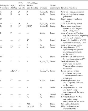
For the non-specialist, subunit nomenclature of different rotary ATPases can appear inconsistent and confusing. Homologous subunits often have different labels and, conversely, some non-homologous subunits have acquired the same label. To clarify this, subunits from V-, A- and F-ATPases of both prokaryotes and eukaryotes are listed in Table 1. Subunits listed across the same row are functional homologues. This homology does not necessarily extend to the sequence level, and subunits that lack sequence similarity can share a common fold, as discussed below. The structure, function and mechanism of F-ATPases from bacteria and eukaryotic organelles have been comprehensively reviewed (Capaldi & Aggeler, Reference Capaldi and Aggeler2002; Devenish et al. Reference Devenish, Prescott and Rodgers2008; Dimroth et al. Reference Dimroth, Von Ballmoos and Meier2006; Müller & Grüber, Reference Müller and Grüber2003; von Ballmoos et al. Reference Von Ballmoos, Cook and Dimroth2008). Core components of the F-ATPases from bacteria and eukaryotes are conserved (Table 1). In the relatively simple ~530 kDa Escherichia coli enzyme, F1 subunits have the stoichiometry (αβ)3:γ:δ:ε, while the membrane domain Fo comprises subunits a:b 2:c 10 (Fig. 1a: left). The mitochondrial F1 and Fo have subunits (αβ)3:γ:δ:ε:OSCP:d:F6 and a:b:c 10, respectively. Mitochondrial δ and bacterial ε are homologous, as are mitochondrial oligomycin sensitivity conferral protein (OSCP) and bacterial δ, whereas mitochondrial ε has no homologue in prokaryotes (Table 1). In this review, we have given the mitochondrial and bacterial polypeptides ‘m’ or ‘b’ designations (δm, δb, εm, εb) to help the reader distinguish between them. Defining the stator and rotor parts of these complexes integrates data from cross-linking (summarised in Capaldi et al. Reference Capaldi, Schulenberg, Murray and Aggeler2000; Capaldi & Aggeler, Reference Capaldi and Aggeler2002), structures and single molecule fluorescence microscopy of complexes executing rotary catalysis (Kinosita et al. Reference Kinosita, Yasuda, Noji, Ishiwata and Yoshida1998; Noji et al. Reference Noji, Yasuda, Yoshida and Kinosita1997; Sambongi et al. Reference Sambongi, Iko, Tanabe, Omote, Iwamoto-Kihara, Ueda, Yanagida, Wada and Futai1999; Ueno et al. Reference Ueno, Suzuki, Kinosita and Yoshida2005; Yoshida et al. Reference Yoshida, Muneyuki and Hisabori2001). The rotor of the mitochondrial F-ATPase comprises γ:δm:εm:c 10, its bacterial equivalent γ:εb:c10–15. Of these components, γ:δm:εm (equivalent to bacterial γ:εb) forms the axle linking the coupled motors, and c 10–15 the ring of membrane subunits that form the rotary part of the ion translocation apparatus (Fig. 1a, b: left). In the static part, each αβ heterodimer is one catalytic unit in a trimeric assembly. The remaining subunits form the stator linkage between the (αβ)3 motor and subunit a, which forms the static part of the ion translocator within the membrane domain.
Subunits of the F-, A- and V-ATPases

a A-ATPase subunits C, H and I are, respectively, homologues of V-ATPase subunits d, G and a. V-ATPase subunits C and H have no homologues in the A-ATPase.
b The δ subunits of mitochondrial and bacterial F-ATPases are not homologous. We refer to them in this review as δm and δb.
c The ε subunits of the mitochondrial and bacterial F-ATPases are not homologous. We refer to them in this review as εm and εb.
d The V-ATPase subunit c is a 4 TMH tandem repeat of the 2-helix F-ATPase c. A-ATPases from different species may contain 2-, 4- or 6-helical c subunits. For clarity, in this review we refer to all forms as subunit c.
A- and V-type ATPases are closely related, with major similarities in subunit arrangement and sequence. The A-type enzyme (Fig. 1a, b: centre) is essentially a simpler version of the V-ATPase (Fig. 1a, b: right), a key difference being the absence of soluble domain C and H subunits from the A-ATPase (Table 1). V1 has subunits A–H in the stoichiometry (AB)3:C:D:F:(EG)3:H (Arai et al. Reference Arai, Terres, Pink and Forgac1988; Kitagawa et al. Reference Kitagawa, Mazon, Heck and Wilkens2008). The equivalent structure in A1 is (AB)3:D:F:(EG)2 (Esteban et al. Reference Esteban, Bernal, Donohoe, Videler, Sharon, Robinson and Stock2008). Although the A-ATPase homologue of V-ATPase subunit G is referred to as H in the A-ATPase literature (Table 1), in this review we will refer to it as G for clarity. The subunits in Vo have a likely a:c 10:d:e stoichiometry, although proton pumping in Saccharomyces also requires two more subunit c isoforms designated c′ (Vma11p) and c″ (Vma16p) (Powell et al. Reference Powell, Graham and Stevens2000; Wang et al. Reference Wang, Cipriano and Forgac2007), the latter perhaps being ubiquitous. In different bacterial and archaeal A-ATPases, the c-subunit may be designated as K, L or c (Table 1), but for consistency and clarity, we refer in this review to these closely related polypeptides exclusively as c-subunits (see footnote to Table 1). Similarly, we refer to the A-ATPase membrane subunit I as subunit a, the designation of its homologues in F- and V-ATPases (Table 1). Although the A-ATPase homologue of the V-ATPase d subunit has historically been referred to as subunit C (Table 1), both appear to occupy similar positions within their respective enzymes (discussed below), pointing to functional homology. To help avoid confusion, we refer here to this A-ATPase subunit as subunit d. In line with these designations, the subunit composition of Ao is a:c 10–12. By analogy to Vo, subunit d is likely also to be part of Ao, but its co-isolation with the membrane domain has not been demonstrated biochemically.
Although the yeast V-ATPase C and H subunits have been solved (Drory et al. Reference Drory, Frolow and Nelson2004; Sagermann et al. Reference Sagermann, Stevens and Matthews2001), the majority of crystal structures are subunits or sub-complexes of bacterial enzymes assigned here as A-type. However, similarities of sequence, secondary structure and inter-subunit contacts established by cross-linking suggest that the A-ATPase subunits are good models for their V-ATPase counterparts (some exceptions to this are discussed below). As in the F-ATPase, assignment of subunits to rotor or stator integrates biochemical/structural data with single molecule rotation studies using yeast (Hirata et al. Reference Hirata, Iwamoto-Kihara, Sun-Wada, Okajima, Wada and Futai2003) and T. thermophilus enzymes (Imamura et al. Reference Imamura, Nakano, Noji, Muneyuki, Ohkuma, Yoshida and Yokoyama2003; Yokoyama et al. Reference Yokoyama, Nakano, Imamura, Yoshida and Tamakoshi2003b). In V- and A-ATPases, these data assign subunits D, F, d and c-ring to the rotor (Yokoyama et al. Reference Yokoyama, Nagata, Imamura, Ohkuma, Yoshida and Tamakoshi2003a) (Fig. 1b, c).
3.3 Organisation of the F1-ATPases
No complete high resolution structure for any F-ATPase complex has been solved to date. The F1 domain is, however, more amenable to crystallography, and has been solved to 1·9 Å (Bowler et al. Reference Bowler, Montgomery, Leslie and Walker2007). Such a high resolution is perhaps surprising, given the intrinsically dynamic and flexible nature of the complex, and is sufficient to see small but significant differences in the geometry of side chains in each active site. The F1 (αβ)3 complex has pseudo-6-fold symmetry, with each α–β interface (viewed with α to the left of the pair, as in Fig. 1a) forming an active site (Abrahams et al. Reference Abrahams, Leslie, Lutter and Walker1994). The three α–β units are in fact not equivalent; each interacts with the asymmetrical γ subunit axle and adopts a different active site conformation. In the F1-ATPase ‘reference structure’ (Abrahams et al. Reference Abrahams, Leslie, Lutter and Walker1994), two catalytic sites have similar conformations (termed βTP and βDP) and bind Mg2+ and AMP-PNP (equivalent to Mg2+-ATP) and Mg2+-ADP, respectively. In virtually all F1-ATPase crystal structures, the third site has a much more open configuration and is empty (βE). During ATP hydrolysis, each site cycles sequentially through E→TP→DP→E states, the transition to the closed βTP state that is driven by ATP binding to one site having knock-on effects on the conformations of the other two. These changes are mediated primarily by the stepped rotation of the axle γ subunit, but are likely to also include effects transmitted through adjoining α subunits. In a crystal structure in which βTP and βDP are occupied by ADP-AlF4−, βE is actually in a ‘half-closed’ conformation bound by ADP and sulphate (mimicking phosphate), and is presumed to reflect the active site state post-hydrolysis but preceding product release (Menz et al. Reference Menz, Walker and Leslie2001). ADP binding to βDP is stabilised by azide that also mimics the binding of inorganic phosphate (Bowler et al. Reference Bowler, Montgomery, Leslie and Walker2006). In the absence of azide, this site can be occupied by AMP-PNP, suggesting that it represents the ‘live’ site poised to hydrolyse ATP (Bowler et al. Reference Bowler, Montgomery, Leslie and Walker2007). The active sites show differences even in the absence of bound Mg2+ and nucleotides (Kabaleeswaran et al. Reference Kabaleeswaran, Puri, Walker, Leslie and Mueller2006), underlining the influence of interactions with the axle. The three conformers equate to the ‘open’, ‘loose’ and ‘tight’ states described by Boyer's binding change mechanism which reconciles the strong negative co-operativity for substrate binding shown by the three catalytic sites with the observed positive co-operativity of catalysis (reviewed in Boyer, Reference Boyer1997). At any point in time, the three sites display either high, medium or low affinity for substrate. By consensus, the ‘open’ βE conformer is the low affinity site. However, the relative affinities of the βDP and βTP sites are a matter of debate: biophysical measurements and free energy difference simulations point to βTP being the high affinity site (Mao & Weber, Reference Mao and Weber2007; Yang et al. Reference Yang, Gao, Cui, Ma and Karplus2003), whereas greater proximity of key catalytic residues to the substrate in the βDP site suggest that it is the catalytically active site and thus represents the high-affinity state (Menz et al. Reference Menz, Walker and Leslie2001).
The γ subunit forms an asymmetric axle that transmits mechanical power from the catalytic complex to the rotary c-ring in Fo (Stock et al. Reference Stock, Leslie and Walker1999; Watts et al. Reference Watts, Zhang, Fillingame and Capaldi1995). The first ~55 and last ~70 residues of this 30 kDa polypeptide fold as an α-helical coiled-coil that extends with pronounced curvature down the centre of F1 to the surface of Fo, where it terminates in a combined α-helix/β-sheet ‘foot’ that includes the β-α-β-α-β topography of a Rossmann fold (Gibbons et al. Reference Gibbons, Montgomery, Leslie and Walker2000). The first short helix of this motif projects like a spur from the bottom of the concave side of the axle. In most F1 structures, the bulge formed by the curvature of the γ subunit axle points towards the αE/βE site. However, crystal structures also show multiple contacts between γ and the interior surface of the (αβ)3 complex, consistent with the idea that γ simultaneously influences conformations of all three catalytic subunits. Correspondingly, all three sites can simultaneously contribute to the generation of rotational movement in the γ axle during ATP hydrolysis (Ariga et al. Reference Ariga, Muneyuki and Yoshida2007). Near the apex of (αβ)3, the C-terminal end of γ is an α-helix that fits into a hydrophobic constriction that may act as a frictionless bearing. However, both C- and N-terminal regions of γ can be truncated with retention of at least some torque generation (Furuike et al. Reference Furuike, Hossain, Maki, Adachi, Suzuki, Kohori, Itoh, Yoshida and Kinosita2008; Müller et al. Reference Müller, Pänke, Junge and Engelbrecht2002). The most important contact for power transmission therefore appears to be between the convex bulge of the γ coiled-coil and a narrow band of (αβ)3 close to the point at which the axle emerges (Junge et al. Reference Junge, Sielaff and Engelbrecht2009; Ma et al. Reference Ma, Flynn, Cui, Leslie, Walker and Karplus2002). This includes a helix-loop-helix feature in the C-terminal domain of β that contains the highly conserved DELSEED sequence. This is proposed to constitute a ‘lever’ that transmits torque from rotor to active site in synthase mode, or applies torque to the axle in ion pump mode. This transmission may involve steric, repulsive van der Waals and electrostatic effects (Bandyopadhyay & Allison, Reference Bandyopadhyay and Allison2004; Ma et al. Reference Ma, Flynn, Cui, Leslie, Walker and Karplus2002; Pu & Karplus, Reference Pu and Karplus2008), although the failure of mutation of negatively charged residues in the DELSEED motif to influence power transmission argues against a role for electrostatics (Hara et al. Reference Hara, Noji, Bald, Yasuda, Kinosita and Yoshida2000).
Bacterial ε (εb) and mitochondrial δ (δm) are homologous polypeptides that associate with γ to form the axle (Table 1), and have distinctive N-terminal β-sandwich and C-terminal helix-loop-helix domains (Gibbons et al. Reference Gibbons, Montgomery, Leslie and Walker2000; Uhlin et al. Reference Uhlin, Cox and Guss1997). The εb/δm co-rotates with γ (Aggeler et al. Reference Aggeler, Ogilvie and Capaldi1997; Rondelez et al. Reference Rondelez, Tresset, Nakashima, Kato-Yamada, Fujita, Takeuchi and Noji2005), with the β-sandwich region positioned at the membrane end of the axle, broadly opposite the foot of γ. The C-terminal region can exist in both compact and extended forms (Hausrath et al. Reference Hausrath, Capaldi and Matthews2001; Rodgers & Wilce, Reference Rodgers and Wilce2000), with switching between states proposed to play a role regulating catalysis (Bulygin et al. Reference Bulygin, Duncan and Cross2004; Kato-Yamada et al. Reference Kato-Yamada, Yoshida and Hisabori2000). ATP promotes the compact, non-inhibitory conformer by directly binding to εb (Kato et al. Reference Kato, Yoshida and Kato-Yamada2007; Kato-Yamada & Yoshida, Reference Kato-Yamada and Yoshida2003; Yagi et al. Reference Yagi, Kajiwara, Tanaka, Tsukihara, Kato-Yamada, Yoshida and Akutsu2007) or via another mechanism (Feniouk et al. Reference Feniouk, Kato-Yamada, Yoshida and Suzuki2010) by which catalysis (in either synthetic or hydrolytic directions) can respond to fluctuations in the ATP concentration. When ATP is low, the extended form of εb contacts the DELSEED loop of the β ‘lever’ and acts as a ratchet allowing rotor movement only in the synthetic direction (Hara et al. Reference Hara, Kato-Yamada, Kikuchi, Hisabori and Yoshida2001; Tsunoda et al. Reference Tsunoda, Rodgers, Aggeler, Wilce, Yoshida and Capaldi2001). Subunit εm has no bacterial equivalent, and is a small polypeptide found at the foot of the axle of the mitochondrial enzyme where it couples to the c-ring. Its role may be to stabilise γ–c-ring coupling.
3.4 Organisation of the Fo membrane domain
Each c-ring subunit folds as a helical hairpin (Rastogi & Girvin, Reference Rastogi and Girvin1999), with the second helix forming an outer ring that interfaces with lipid (Meier et al. Reference Meier, Polzer, Diederichs, Welte and Dimroth2005a). H+/Na+ discrimination by bacterial c-rings is a function of the character and geometry of side chains arranged around a critical and highly conserved aspartate positioned mid-membrane on this outer helix (von Ballmoos et al. Reference Von Ballmoos, Cook and Dimroth2008). In synthase mode, the c-ring forms the torque generator in combination with subunit a, a single copy of which forms the membrane-embedded part of the F-ATPase stator. Subunit a and the integral membrane part of subunit b are the parts of the F-ATPase for which least structural data are available, and these hydrophobic components may represent the main obstacles for obtaining a complete high-resolution structure. Progress has however been made on the structures of c-rings from F-ATPases from both bacterial and eukaryotic sources, fuelling debate about the functional significance of variations in subunit stoichiometry and the consequent cation/ATP ratio. In the E. coli F-ATPase, a decameric c-ring may be the default size (Jiang et al. Reference Jiang, Hermolin and Fillingame2001), although the functionality of genetic fusions suggests that other stoichiometries may be tolerated (Jones & Fillingame, Reference Jones and Fillingame1998). In contrast, crystal structures of the c-rings from Na+-translocating F-ATPases of Ilyobacter tartaricus and P. modestum have c 11 stoichiometry (Meier et al. Reference Meier, Polzer, Diederichs, Welte and Dimroth2005a, Reference Meier, Yu, Raschle, Henzen, Dimroth and Mullerb, Reference Meier, Ferguson, Cook, Dimroth and Vonck2006), and AFM analyses give stoichiometries ranging between 13 and 15 for cyanobacterial enzymes (Pogoryelov et al. Reference Pogoryelov, Yu, Meier, Vonck, Dimroth and Muller2005, Reference Pogoryelov, Reichen, Klyszejko, Brunisholz, Muller, Dimroth and Meier2007). This variability extends to the c-rings of F-ATPases from eukaryotic organelles: the spinach chloroplast enzyme has 14 c-subunits (Seelert et al. Reference Seelert, Poetsch, Dencher, Engel, Stahlberg and Müller2000; Vollmar et al. Reference Vollmar, Schlieper, Winn, Büchner and Groth2009), whereas the yeast mitochondrial ATP synthase has only 10 (Stock et al. Reference Stock, Leslie and Walker1999). Uniquely, the bacterium A. woodii produces ATP using an enzyme that contains nine F-ATPase-type helical hairpin c-subunits associated with a single copy four transmembrane helix (TMH) c-subunit typically found in A- and V-ATPases (Fritz et al. Reference Fritz, Klyszejko, Morgner, Vonck, Brutschy, Muller, Meier and Müller2008; Rahlfs et al. Reference Rahlfs, Aufurth and Müller1999). The membrane domain in A. woodii is essentially therefore a hybrid Fo/Vo, although the advantages conferred by this organisation remain to be determined.
Why is the c-subunit stoichiometry so variable? One proposal that attempts to accommodate the rather variable H+/ATP ratios that have been reported is that an organism can adjust its c-ring stoichiometry such that it is optimised for particular physiological conditions (Tomashek & Brusilow, Reference Tomashek and Brusilow2000). If one considers the energetic cost of making ATP to be essentially fixed, growth conditions resulting in a smaller ion motive force would demand a greater number of ion translocation events per enzyme cycle, reflected as a larger c-ring stoichiometry. Despite the attraction of this model, several studies have found c-ring stoichiometries in individual organisms to remain fixed irrespective of growth conditions (Ballhausen et al. Reference Ballhausen, Altendorf and Deckers-Hebestreit2009; Fritz et al. Reference Fritz, Klyszejko, Morgner, Vonck, Brutschy, Muller, Meier and Müller2008; Meyer zu Tittingdorf et al. Reference Meyer zu Tittingdorf, Rexroth, Schafer, Schlichting, Giersch, Dencher and Seelert2004). It seems therefore that each organism has one c-ring size customised to its specific physiology, an adaptation to the prevailing ion motive force under which its F-ATPase operates (von Ballmoos et al. Reference Von Ballmoos, Cook and Dimroth2008). The electrical component (Δψ) of a PMF has been shown to be kinetically more effective at energising ATP synthesis than the ΔpH proton gradient (discussed in von Ballmoos et al. Reference Von Ballmoos, Cook and Dimroth2008; Dimroth et al. Reference Dimroth, Von Ballmoos and Meier2006). Mitochondria and some bacteria that maintain a relatively stable ΔμX+ to which the electrical component is the main contributor may therefore be able to energise ATP synthesis with smaller c-rings. Larger c-rings (and therefore larger H+/ATP ratios) are proposed to represent an evolutionary compromise that allows F-ATPases such as those in chloroplasts and cyanobacteria to be energised by a PMF that has only a ΔpH component. Irrespective of the overall magnitude of ΔμX+, such systems would require a greater number of ion translocation events per ATP synthesised, hence larger c-rings. For a more complete discussion of this topic, see von Ballmoos et al. (Reference Von Ballmoos, Cook and Dimroth2008, Reference Von Ballmoos, Wiedenmann and Dimroth2009). This issue is far from resolved, however: although particular cation/ATP ratios may be deduced from c-ring stoichiometries (c-ring size/3), measurements of actual operational H+/ATP ratios often fail to match up to these numbers (Junge et al. Reference Junge, Sielaff and Engelbrecht2009; Steigmiller et al. Reference Steigmiller, Turina and Gräber2008; Tomashek & Brusilow, Reference Tomashek and Brusilow2000). From a membrane protein assembly perspective, it remains unclear what organism-specific features govern assembly of similar c-subunits into rings of different sizes in different membranes.
Extensive mutagenesis studies have shown that stator subunit a is also directly involved in transmembrane ion movement (reviewed in Cain, Reference Cain2000). Low-resolution models based on sequence analysis and supported by cross-linking and site-directed labelling studies suggest that this polypeptide folds with five TMHs, with TMHs 2–5 packing as a four-helical bundle (Schwem & Fillingame, Reference Schwem and Fillingame2006). Cross-linking supports a model in which TMH 4 (containing the functionally crucial Arg210 (E. coli residue number; Cain & Simoni, Reference Cain and Simoni1989; Valiyaveetil & Fillingame, Reference Valiyaveetil and Fillingame1997; Vik et al. Reference Vik, Patterson and Antonio1998)) and TMH5 are adjacent to the external surface of the c-ring, in contact with at least two neighbouring c-subunits (Jiang & Fillingame, Reference Jiang and Fillingame1998; Moore & Fillingame, Reference Moore and Fillingame2008) that step through the a/c-ring interface during rotation (Hutcheon et al. Reference Hutcheon, Duncan, Ngai and Cross2001). Topological models place the N-terminal end of TMH4 on the cytoplasmic side of the membrane (see pdb 1C17; Rastogi & Girvin, Reference Rastogi and Girvin1999). Full function requires the crucial arginine and aspartate to be at the same depth in the membrane (Langemeyer & Engelbrecht, Reference Langemeyer and Engelbrecht2007), implying close proximity between their side chains. This is consistent with a role for the positive charge of the arginine in the Brownian ratchet mechanism of the Fo motor (see section 4.1).
3.5 The F-ATPase stator is different in bacteria and eukaryotes
The part of the stator linking subunit a to (αβ)3 varies most between bacterial and organellar F-ATPases. In E. coli, it comprises the δ subunit (δb) linked to a subunit b dimer (Dunn et al. Reference Dunn, Revington, Cipriano and Shilton2000; Rodgers et al. Reference Rodgers, Wilkens, Aggeler, Morris, Howitt and Capaldi1997) (Fig. 1a). The δb subunit associates with α at the top of F1 (Dunn et al. Reference Dunn, Revington, Cipriano and Shilton2000; Ogilvie et al. Reference Ogilvie, Aggeler and Capaldi1997; Rodgers & Capaldi, Reference Rodgers and Capaldi1998) and contacts the C-terminal end of the subunit b dimer (McLachlin et al. Reference Mclachlin, Bestard and Dunn1998). The strength of this interaction is sufficient to resist the torque generated by the ATPase motor (Häsler et al. Reference Häsler, Pänke and Junge1999; Weber et al. Reference Weber, Wilke-Mounts, Nadanaciva and Senior2004). Each b subunit is essentially a single α-helix that extends from its contact with δb to an N-terminal integral membrane segment, in contact with subunit a and adjacent to the external surface of the c-ring (Jones et al. Reference Jones, Hermolin, Jiang and Fillingame2000; McLachlin et al. Reference Mclachlin, Coveny, Clark and Dunn2000). The b subunit remains associated with Fo when F1 detaches from the membrane. In the mitochondrial enzyme, the δb subunit homologue OSCP (Table 1) makes very similar contacts: its N-terminal region binds with high affinity to α (Carbajo et al. Reference Carbajo, Kellas, Yang, Runswick, Montgomery, Walker and Neuhaus2007) and its C-terminal region forms strong helix–helix interactions with the C-terminal end of the single b α-helix (Rees et al. Reference Rees, Leslie and Walker2009). The N-terminal region of the single b polypeptide in the mitochondrial complex is predicted to contain two TMHs, but has only a single extramembranous α-helix reinforced by α-helices contributed by the d and F6 subunits (Dickson et al. Reference Dickson, Silvester, Fearnley, Leslie and Walker2006). Several small subunits also associate with the stator in mitochondrial Fo (Table 1), with functions that may include promoting stability through dimerisation and formation of supramolecular complexes (Devenish et al. Reference Devenish, Prescott and Rodgers2008 and references therein).
3.6 Core subunits of the rotary ATPases are related
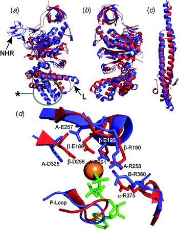
Subunits A and B are highly conserved between A- and V-ATPases, and their sequences indicate the same common ancestor as F-ATPase β and α subunits. Comparison of crystal structures of A-ATPase A (Maegawa et al. Reference Maegawa, Morita, Iyaguchi, Yao, Watanabe and Tanaka2006), B (Schäfer et al. Reference Schäfer, Bailer, Duser, Börsch, Bernal, Stock and Grüber2006) and the (AB)3 complex (Maher et al. Reference Maher, Akimoto, Iwata, Nagata, Hori, Yoshida, Yokoyama, Iwata and Yokoyama2009) with F1 underlines their similarity to β and α, but also illustrates key differences (Fig. 2a, b). Most striking is the presence of the ‘non-homologous region’ (NHR) of subunit A, an ~80 residue β-structure region that projects from the surface of V1 (Fig. 2a). Mutations in the NHR of the Saccharomyces polypeptide influence coupling efficiency and the ability of the yeast enzyme to undergo controlled domain dissociation in response to physiological signals, suggesting a role in regulation (Shao et al. Reference Shao, Nishi, Kawasaki-Nishi and Forgac2003; Shao & Forgac, Reference Shao and Forgac2004). How this might work is not clear, and similar regulatory mechanisms have not been demonstrated in A-ATPases even though the NHR is conserved. Most of the remaining fold of A is very similar to β, although the C-terminal region of A does differ in that the three α-helices closest to the membrane domain are significantly longer than in β (Fig. 2a) (Maher et al. Reference Maher, Akimoto, Iwata, Nagata, Hori, Yoshida, Yokoyama, Iwata and Yokoyama2009). The significance of this is unclear, although this region does contain the helix-loop-helix ‘lever’ structure involved in torque generation (labelled ‘L’ in Fig. 2a), with partial conservation of the F-ATPase DELSEED sequence. In the 2·8 Å structure of the (AB)3 complex from T. thermophilus, crystallised in the absence of nucleotides, all three active sites adopt the same configuration, resembling that of the βE site in F-ATPase (Maher et al. Reference Maher, Akimoto, Iwata, Nagata, Hori, Yoshida, Yokoyama, Iwata and Yokoyama2009). In a more complete (but lower resolution) model of the T. thermophilus A1 that also includes the D and F axle subunits, the three AB units adopt different conformations and two active sites contain ADP (Numoto et al. Reference Numoto, Hasegawa, Takeda and Miki2009), mirroring the situation in the ‘reference’ F1-ATPase co-crystallised with nucleotides (Abrahams et al. Reference Abrahams, Leslie, Lutter and Walker1994). Adoption of different active site conformations therefore requires nucleotide binding, interaction with D, or both.
Structures of rotary ATPase core subunits are conserved. (a) Overlay of the T. thermophilus A subunit (blue: pdb 3GQB) with the yeast β subunit (red: pdb 2HLD). Subunit A is presumed to be in the ‘empty’ state (see text for details) and is compared to the βE conformer. There is extensive common fold, the key differences being the subunit A ‘NHR’ and the length of the α-helices in the C-terminal region of A (ringed). The helix-loop-helix region that in F-ATPase β contains the conserved DELSEED sequence (DALQDAE in T. thermophilus A) and acts as the lever that interacts with the axle is also highlighted (L). (b) Overlay of T. thermophilus B (blue) and yeast α (red) subunits shows the high degree of similarity in fold. (c) Despite no apparent sequence similarity, residues 1–55/132–205 of the T. thermophilus D subunit (blue: pdb 3A5D) fold as a coiled-coil very similar to the γ subunit that forms the axle of the F-ATPase. (d) Overlay of the active sites of T. thermophilus A-ATPase (blue) and yeast F-ATPase (red). To aid with orientation around bound nucleotide (green) and Mg2+ ion (orange sphere), the yeast (αβ)DP site is shown. β-E189 and A-E257 are equivalent to β-E188 of the bovine enzyme proposed to activate a bound water molecule for nucleophilic attack on the γ-phosphate of ATP (Abrahams et al. Reference Abrahams, Leslie, Lutter and Walker1994). Overall similarities in active site organisation point to fundamentally similar reaction chemistries in all three ATPases.

Overall, side chains arrangements in A1/V1 and F1 active sites are remarkably conserved (Fig. 2d), suggesting similar reaction chemistries. In particular, this includes a glutamate residue (β-E189 and A-E257 in Fig. 2d) proposed to activate bound water for nucleophilic attack on the γ-phosphate of ATP during hydrolysis, and the ‘arginine finger’ residue (α-R375 and B-R360 in Fig. 2d) positioned to stabilise the penta-coordinate transition state of the γ-phosphate. Crucially, this residue changes position during the transition from ‘open’ to ‘closed’ active site states. Although the fold of B closely resembles that of F-ATPase α (Fig. 2b), the P-loop that contains a Walker A motif involved in nucleotide binding by A, α and β is not conserved. In line with this, but in contrast to the situation in the F1-ATPase (Abrahams et al. Reference Abrahams, Leslie, Lutter and Walker1994), the non-catalytic A–B interfaces in A1 do not bind ADP (Numoto et al. Reference Numoto, Hasegawa, Takeda and Miki2009). Any possible function performed by these nucleotides in F-ATPase is therefore not conserved in the A- or V-ATPases. This difference, the presence of the NHR, or more subtle differences such as the arrangement of hydrophobic residues around the A1 active site (Maher et al. Reference Maher, Akimoto, Iwata, Nagata, Hori, Yoshida, Yokoyama, Iwata and Yokoyama2009) could account for divergence in reaction mechanisms observed as differences in the stepping characteristics of the rotor in A1 compared with F1 (Imamura et al. Reference Imamura, Takeda, Funamoto, Shimabukuro, Yoshida and Yokoyama2005).
3.7 Subunit organisation in the rotors of A- and V-ATPases
Sequences of D subunits of the central stalks of the A- and V-ATPases are dissimilar to the F-ATPase γ subunit, implying no common ancestor. Comparison of D and γ structures does, however, show that they are both coiled-coils of α-helices (Numoto et al. Reference Numoto, Hasegawa, Takeda and Miki2009) (Fig. 2c). Subunit F is also conserved across A- and V-type complexes, albeit with somewhat lower (~28%) identity. Subunit F has been proposed to promote catalytic activity in the A1-ATPase (Imamura et al. Reference Imamura, Ikeda, Yoshida and Yokoyama2004), with the polypeptide able to adopt ‘extended’ and ‘contracted’ conformations in which the positions of the C-terminal ~40 residues vary dramatically (Makyio et al. Reference Makyio, Iino, Ikeda, Imamura, Tamakoshi, Iwata, Stock, Bernal, Carpenter, Yoshida, Yokoyama and Iwata2005). In the (AB)3:D:F crystal structure, F adopts a different, possibly intermediate conformation, with its C-terminal segment extending up to contact a helix-loop-helix feature in the C-terminal domain of an A subunit (Numoto et al. Reference Numoto, Hasegawa, Takeda and Miki2009). This A subunit feature is homologous to the ‘lever’ of the F-ATPase β subunit that contains the conserved DELSEED sequence and is involved in energy transfer between the axle of the rotor and (αβ)3 catalytic complex. The positioning of the C-terminal segment of F in the A1 crystal structure suggests a ratchet-like function that could prevent the counter-clockwise rotation of subunit D (as viewed from the membrane) expected to result from ATP hydrolysis. This conformational flexibility of F is remarkably similar to that shown by the bacterial F-ATPase εb subunit that occupies a similar rotor location, although F and εb share no other obvious similarities. Interestingly, the fold of subunit F resembles that of CheY (Makyio et al. Reference Makyio, Iino, Ikeda, Imamura, Tamakoshi, Iwata, Stock, Bernal, Carpenter, Yoshida, Yokoyama and Iwata2005), a bacterial chemotaxis response regulator that influences the directionality of flagellar rotation according to its phosphorylation state.
The 4TMH V-ATPase c-subunits appear to have evolved as a tandem repeat of the same 2 TMH progenitor that gave rise to F-ATPase subunit c, but retaining only one conserved proton-carrying glutamate on its fourth TMH. In the A-ATPases, H+ or Na+-specific forms of either the 2- or 4-helical forms occur in different species, perhaps as a result of exchange of genes between archaea and eubacteria (Mulkidjanian et al. Reference Mulkidjanian, Galperin, Makarova, Wolf and Koonin2008; Müller et al. Reference Müller, Lingl, Lewalter and Fritz2005). The archaeon Methanocaldococcus jannaschi expresses a 6TMH c-subunit consisting of a triple repeat of the 2TMH helical hairpin, with the ion translocating residue deleted from the first 2TMH repeat element (Müller & Grüber, Reference Müller and Grüber2003). Data relating to the subunit c stoichiometry in A- and V-ATPase are limited, but suggest variability. The Na+-specific c-ring of E. hirae is a decamer of ‘V-ATPase type’ 4TMH polypeptides (Murata et al. Reference Murata, Yamato, Kakinuma, Leslie and Walker2005), whereas the c 12 ring from T. thermophilus contains ‘F-ATPase type’ 2TMH subunits (Toei et al. Reference Toei, Gerle, Nakano, Tani, Gyobu, Tamakoshi, Sone, Yoshida, Fujiyoshi, Mitsuoka and Yokoyama2007). Uniquely, the archaeon Methanopyrus kandleri has a gene encoding a single c-type polypeptide that is a 13-mer repeat of the F-type helical hairpin polypeptide (Slesarev et al. Reference Slesarev, Mezhevaya, Makarova, Polushin, Shcherbinina, Shakhova, Belova, Aravind, Natale, Rogozin, Tatusov, Wolf, Stetter, Malykh, Koonin and Kozyavkin2002), but it is unclear if this is indicative of a commonly occuring stoichiometry. Superficially, the 2TMH pattern appears to be an adaptation to the ATP synthase function, whereas the 4TMH version may be an ion pump feature. However, this does not hold under scrutiny: although the A-ATPase of archaeal Pyrococcus species appears essentially identical to the ATP-driven Na+ pump of the bacterium E. hirae, both having decameric c-rings of the 4TMH ‘V-ATPase-type’, the Pyrococcus enzyme can operate in either ion pump or synthase modes (Müller & Grüber, Reference Müller and Grüber2003). In the V-ATPase, polypeptides closely related to the 4TMH subunit c also assemble as hexamers (Clare et al. Reference Clare, Orlova, Finbow, Harrison, Findlay and Saibil2006), consistent with biochemical measurements of stoichiometry performed on the coated vesicle enzyme (Arai et al. Reference Arai, Terres, Pink and Forgac1988). A low H+/ATP ratio in V-ATPases in particular could indicate a low gearing that would permit proton translocation against even a large, unfavourable pH gradient. However, the c-ring stoichiometry in the V-ATPase remains uncertain: the c 10 ring from the E. hirae A-ATPase, rather than a hexameric model, proved to be the best fit to electron density maps of the Manduca enzyme (Muench et al. Reference Muench, Huss, Song, Phillips, Wieczorek, Trinick and Harrison2009).
The d subunit of the A- and V-ATPases has no homologue in the F-ATPase. It is proposed to couple the membrane end of the D/F axle to the c-ring (Iwata et al. Reference Iwata, Imamura, Stambouli, Ikeda, Tamakoshi, Nagata, Makyio, Hankamer, Barber, Yoshida, Yokoyama and Iwata2004). The crystal structure of the T. thermophilus d subunit shows a bundle of seven long (30–39 Å) helices surrounded by a ring of shorter helical segments, giving an overall conical shape that is complementary to the cytoplasmic surface of the rotor ring (Iwata et al. Reference Iwata, Imamura, Stambouli, Ikeda, Tamakoshi, Nagata, Makyio, Hankamer, Barber, Yoshida, Yokoyama and Iwata2004). Subunit d has therefore been proposed to tightly plug the socket formed by c-ring cylinder. Consistent with this, subunit d binding to the V-ATPase c-ring appears to be very tight, with chaotropic agents required to strip it from Vo (Bauerle et al. Reference Bauerle, Ho, Lindorfer and Stevens1993). X-ray scattering analysis of the yeast d subunit shows a ‘boxing glove’ shape that is stabilised by intramolecular disulphide bonds (Thaker et al. Reference Thaker, Roessle and Grüber2007). The ‘wrist’ of this structure could be inserted into the middle of the c-ring. In the V-ATPase, mutations in subunit d can affect coupling between ATP hydrolysis and H+ translocation (Owegi et al. Reference Owegi, Pappas, Finch, Bilbo, Resendiz, Jacquemin, Warrier, Trombley, McCulloch, Margalef, Mertz, Storms, Damin and Parra2006), implying that they break the coupling between axle and c-ring or cause it to slip under load. Alternatively, mutations could allow uncoupled leakage of protons back across the membrane (‘proton slip’; Nelson et al. Reference Nelson, Perzov, Cohen, Hagai, Padler and Nelson2000).
3.8 Peripheral stator components of the rotary ATPases share common features
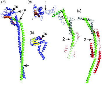
Structures of the mitochondrial F-ATPase stator have been solved both as a partial b:d:F6:OSCP complex within the membrane extrinsic part of the enzyme (Rees et al. Reference Rees, Leslie and Walker2009), and as an autonomously assembling b:d:F6 sub-complex missing only the integral membrane part of b (Dickson et al. Reference Dickson, Silvester, Fearnley, Leslie and Walker2006) (Fig. 3). These show that the extrinsic region of b is a single extended α-helix that is reinforced by shorter helical segments from d and F6 (Fig. 3c, d). The strength of the OSCP-b linkage comes from extensive helical interactions.
Stator crystal structures. (a) The A-ATPase E:G sub-complex from T. thermophilus (pdb 3K5B) at 3·1 Å resolution comprising residues 2–188 of subunit E (blue) and 21–120 of subunit G (green). Residues in the globular domain of E involved in binding to the B subunit are orange. TS indicates the position of the temperature-sensitive mutation in the homologous Saccharomyces E subunit. Potentially flexible points in E and G are asterisked. The point towards the foot of the α-helical region arrowed can be cross-linked to subunit C in yeast V-ATPase (Jones et al. Reference Jones, Durose, Phillips, Keen, Findlay and Harrison2010). (b) Residues 81–198 of Pyrococcus hirokoshii subunit E (pdb 2DM9: Lokanath et al. Reference Lokanath, Matsuura, Kuroishi, Takahashi and Kunishima2007) at 1·85 Å, detailing the β-sheet structure in the globular domain. (c) Partial stator structure from the membrane extrinsic part of the bovine mitochondrial F-ATPase at 3·2 Å (pdb 2WSS), comprising residues 122–207 of b (green), 5–25/35–57 of F6 (grey), 1–146/169–189 of OSCP (blue) and three short α-helical segments of d (red). Residues in OSCP involved in binding to the α subunit are orange. (d) Bovine F-ATPase sub-complex (pdb 2CLY) at 2·8 Å, containing subunit b with its transmembrane α-helical region deleted (residues 79–183: green), and residues 8–123 and 5–70 of subunits d (red) and F6 (grey), respectively. The C-terminal α-helical segment of b apparent in (c) is not resolved. In (c) and (d), 1 and 2 indicate proposed points of flexibility (discussed in section 3.8).

In the A- and V-ATPases, the structure comparable to F-ATPase b:d:F6:OSCP comprises only E and G subunits (Table 1). E:G spontaneously assembles as a highly stable 1:1 heterodimer in bacterial expression systems, although both bacterial and archaeal G polypeptides in isolation form dimers or higher order filamentous aggregates (Jones et al. Reference Jones, Durose, Phillips, Keen, Findlay and Harrison2010; Kish-Trier et al. Reference Kish-Trier, Briere, Dunn and Wilkens2008). G shares sequence similarity with the extramembranous region of the F-ATPase b subunit (Hunt & Bowman, Reference Hunt and Bowman1997; Supekova et al. Reference Supekova, Sbia, Supek, Ma and Nelson1996), indicating a common origin. Crystal structures of the A-ATPase E:G (Lee et al. Reference Lee, Stewart, Donohoe, Bernal and Stock2010a) and F-ATPase b:d:F6:OSCP (Dickson et al. Reference Dickson, Silvester, Fearnley, Leslie and Walker2006) sub-complexes show that G and b have remarkably similar extended α-helical folds (Fig. 3). In the E:G heterodimer, a ~130 Å-long G helix runs parallel to a second helix of similar length contributed by E, with the two forming a right-handed coiled-coil (Fig. 3a). The C-terminal end of G interacts with the globular C-terminal domain of E (Jones et al. Reference Jones, Durose, Phillips, Keen, Findlay and Harrison2010; Kish-Trier & Wilkens, Reference Kish-Trier and Wilkens2009a), which also interacts with the N-terminal region of subunit B at the apex of the soluble domain (Kish-Trier & Wilkens, Reference Kish-Trier and Wilkens2009b), analogous to the interactions between δb/OSCP and α in the F-ATPase. A similar structure for the V-ATPase E:G sub-complex may be expected, given the sequence conservation between the A- and V-ATPase components. A- and V-ATPase E:G heterodimers also share similar secondary structure, and both form ~160–180 Å filaments consistent with a stator role linking the soluble and membrane domains (Féthière et al. Reference Féthière, Venzke, Diepholz, Seybert, Geerlof, Gentzel, Wilm and Böttcher2004, Reference Féthière, Venzke, Madden and Böttcher2005; Harrison et al. Reference Harrison, Durose, Song, Barratt, Trinick, Jones and Findlay2003; Jones et al. Reference Jones, Durose, Phillips, Keen, Findlay and Harrison2010; Kish-Trier et al. Reference Kish-Trier, Briere, Dunn and Wilkens2008; Yamamoto et al. Reference Yamamoto, Unzai, Saijo, Ito, Mizutani, Suno-Ikeda, Yabuki-Miyata, Terada, Toyama, Shirouzu, Kobayashi, Kakinuma, Yamato, Yokoyama, Iwata and Murata2008). In the yeast E:G heterodimer, the N-terminal regions of the two polypeptides appear quite closely aligned (Rishikesan et al. Reference Rishikesan, Thaker, Priya, Gayen, Manimekalai, Hunke and Grüber2008). A key difference between the A- and V-ATPases is the stoichiometry of the E:G subunits: Mass spectrometric approaches indicate three copies of E:G in the V-ATPase (Kitagawa et al. Reference Kitagawa, Mazon, Heck and Wilkens2008), but only two copies in the A-type complex (Esteban et al. Reference Esteban, Bernal, Donohoe, Videler, Sharon, Robinson and Stock2008). This difference is discussed below in the context of the 3D models generated by EM.
Both F- and V/A-ATPase stators have been proposed to include particular points that might confer flexibility (Lee et al. Reference Lee, Stewart, Donohoe, Bernal and Stock2010a; Rees et al. Reference Rees, Leslie and Walker2009), a property that may play a role in ATPase mechanics. In the F-ATPase, these are between the α-binding and b/d-binding domains of OSCP and at a point at which the b subunit bends (labelled 1 and 2 in Fig. 3c, d). Flexion points in E:G have been suggested near the C-terminal end of G and at the junction between N-terminal α-helical and globular domain of E (asterisk, Fig. 3a).
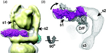
Subunits C and H are the only subunits without functional homologues in either the F- or A-type ATPases (Table 1). Subunit C has a ~110 Å-long ‘dogbone’ structure (Drory et al. Reference Drory, Frolow and Nelson2004), and fits into the stator of the V-ATPase (Fig. 1c), where it contacts the N-terminal region of subunit E (Fig. 3a legend). It has been proposed to have a regulatory function, being phosphorylated in insects by protein kinase A in response to physiological signals (Voss et al. Reference Voss, Vitavska, Walz, Wieczorek and Baumann2007), and by the With no K (lysine) (WNK) kinase in Arabidopsis (Hong-Hermesdorf et al. Reference Hong-Hermesdorf, Brux, Grüber, Grüber and Schumacher2006). Loss of C from the V-ATPase has been shown in yeast and insects to be linked to the reversible dissociation of the V1 from the membrane and ATPase inactivation (Kane, Reference Kane1995; Merzendorfer et al. Reference Merzendorfer, Reineke, Zhao, Jacobmeier, Harvey and Wieczorek2000; Parra et al. Reference Parra, Keenan and Kane2000). A similar phenomenon in yeast is also dependent on protein kinase A activity, although phosphorylation of subunit C in Saccharomyces has not been directly demonstrated (Bond & Forgac, Reference Bond and Forgac2008). Subunit H has two distinct domains assembled as an ‘L-shape’ (Sagermann et al. Reference Sagermann, Stevens and Matthews2001), and is also proposed to function as a V-ATPase regulator. Domain dissociation in yeast induces a change in position of H within the V1 complex such that its C-terminal domain comes into contact with the D:F axle (Jefferies & Forgac, Reference Jefferies and Forgac2008; Diab et al. Reference Diab, Ohira, Liu, Cobb and Kane2009), presumably restricting its movement and thereby preventing ADP/ATP exchange in the active sites. The absence of homologues of these subunits from either F- or A-type ATPases presumably reflects the evolution of more sophisticated control mechanisms in eukaryotic V-ATPases, driven by the necessity to conserve ATP during periods of physiological stress.
3.9 V/A-ATPase stator subunit a is a polytopic protein with two domains
As in the F-ATPase, subunit a forms the membrane-embedded end of the stator in the A- and V-ATPases and, like its Fo equivalent, includes residues involved in H+ translocation (Kawasaki-Nishi et al. Reference Kawasaki-Nishi, Nishi and Forgac2001; Leng et al. Reference Leng, Manolson, Liu and Forgac1996, Reference Leng, Manolson and Forgac1998). Also like F-ATPase subunit a, it is the subunit for which we have the least structural information. Although hydropathy analysis suggests that the ~95 kDa V-ATPase a subunit folds with ~40 kDa N-terminal soluble (a N) and ~55 kDa integral membrane (a C) domains, the heterologously expressed a N domain has also been reported to have integral membrane protein characteristics: its folding is stabilised by detergent, and it co-precipitates with synthetic liposomes (Merkulova et al. Reference Merkulova, McKee, Dip, Grüber and Marshansky2010). The a N domain contributes to a collar structure that links together C, E, G and H subunits (see Fig. 1). Early topographic models suggested 7–9 TMHs (Kawasaki-Nishi et al. Reference Kawasaki-Nishi, Nishi and Forgac2001; Leng et al. Reference Leng, Nishi and Forgac1999), but a recent study (Wang et al. Reference Wang, Toei and Forgac2008) has produced a more plausible 8 TMH model, with the N-terminal domain cytoplasmically located. An even number of helices exposes the C-terminal tail to the cytoplasm, consistent with it binding to cytoplasmic phosphofructokinase-1 (Su et al. Reference Su, Zhou, Al Lamki and Karet2003). Secondly, it places functionally critical Arg, His and Glu residues within TMH 7 and 8 (Arg735, His743 and Glu789 in the Saccharomyces subunit a, Vph1p) in an arrangement that closely parallels that of similar residues in TMH 4 and 5 of the F-ATPase subunit a (Kawasaki-Nishi et al. Reference Kawasaki-Nishi, Nishi and Forgac2001). The residue equivalent to the yeast Arg735 is contained within a conserved LRLWXXXXA motif, a version of which (RLXXXXXA) also persists in the F-ATPase a subunit. Topography with 8 TMH gives V-ATPase subunit a TMH7 and F-ATPase subunit a TMH4 the same orientation with respect to the cytoplasmic surface of the membrane. Complete traversing of the bilayer by each putative TMH is inferred, but may not be the case. Helical structures at the c-ring interface could be sequestered from the hydrophobic phase, allowing formation of ‘helix loops’ such as those found in the interiors of a number of channel proteins.
Even less is known about the topography of the 72–76 kDa A-ATPase homologue of subunit a (Table 1). Analysis with TMPred (Hofmann & Stoffel, Reference Hofmann and Stoffel1993) suggests that A-ATPase subunit a has a C-terminal 6 TMH and a ~38 kDa soluble N-terminal domain (Harrison, Muench and Trinick, unpublished results), although a seven TMH model has also been proposed (Müller et al. Reference Müller, Ruppert and Lemker1999). As in the V-ATPase homologue, the A-ATPase aN domain forms a collar structure that links together the two sets of EG heterodimeric components (Fig. 1). Limited sequence similarity between predicted helices 7/8 of V-ATPase a and 5/6 of its A-ATPase homologue suggests some conservation of this region across all rotary ATPases. Other regions of V-ATPase and A-ATPase a subunits are, however, highly divergent, with the V-ATPase polypeptide also containing a ~200-residue insert predicted to include a 60–70-residue extramembranous region on the cytoplasmic side of the membrane (Harrison, Muench and Trinick, unpublished observations). Thus, the V- and A-type subunits show some clear similarities in the organisation of helices directly involved in ion translocation, paralleling a similar structure in the F-ATPase subunit a, but with the V-ATPase subunit having additional complexity perhaps linked to more sophisticated regulation in eukaryotes.
Vo also contains subunit e, a small (8·4–9·7 kDa) and highly hydrophobic polypeptide first observed in V-ATPase preparations from bovine chromaffin granules (Ludwig et al. Reference Ludwig, Kerscher, Brandt, Pfeiffer, Getlawi, Apps and Schägger1998) and later identified in Manduca sexta as an integral part of the V-ATPase (Merzendorfer et al. Reference Merzendorfer, Huss, Schmid, Harvey and Wieczorek1999). It was subsequently found to also be an essential component of the yeast enzyme (Davis-Kaplan et al. Reference Davis-Kaplan, McVEY Ward, Shiflett and Kaplan2004; Sambade & Kane, Reference Sambade and Kane2004). Although we can presume that it is associated with subunit a in the membrane-embedded part of the stator, its precise function remains uncertain, and no equivalent has been found in the A-ATPases.
Further parallels can be drawn between the F- and V-ATPase membrane subunits through examination of their roles in inhibitor binding. Oligomycin resistance-conferring mutations map onto the lipid-exposed surface of the c-ring structures, and tributyl tin compounds also target Fo, most likely subunit a or the crucial a/c-ring interface (von Ballmoos et al. Reference Von Ballmoos, Brunner and Dimroth2004). The bafilomycin-type compounds that target the V-ATPase subunit c (Bowman & Bowman, Reference Bowman and Bowman2002; Huss et al. Reference Huss, Ingenhorst, Konig, Gassel, Drose, Zeeck, Altendorf and Wieczorek2002; Whyteside et al. Reference Whyteside, Meek, Ball, Dixon, Finbow, Kee, Findlay and Harrison2005) also access its membrane-embedded surface via the lipid phase (Dixon et al. Reference Dixon, Pali, Kee and Marsh2004, Reference Dixon, Pali, Kee, Ball, Harrison, Findlay, Nyman, Väänänen, Finbow and Marsh2008; Pali et al. Reference Pali, Dixon, Kee and Marsh2004), mirroring the site and mode of action of oligomycin in the F-ATPase (Fillingame et al. Reference Fillingame, Angevine and Dmitriev2002; Vik et al. Reference Vik, Long, Wada and Zhang2000). The likely involvement of V-ATPase subunit a in bafilomycin binding (Wang et al. Reference Wang, Inoue and Forgac2005) further implies that the effects of these compounds result directly from interference with the dynamic interface between the a-subunit and the c-ring.
4. Rotary ATPase mechanics
4.1 Torque generation
How does this assembly generate torque to power the complex in synthase mode? A model based on a Brownian ratchet mechanism has been developed (Dimroth et al. Reference Dimroth, Von Ballmoos and Meier2006; Junge et al. Reference Junge, Lill and Engelbrecht1997, Reference Junge, Sielaff and Engelbrecht2009; Vik & Antonio, Reference Vik and Antonio1994), supported by mechanochemical simulations and consistent with structural data (Elston et al. Reference Elston, Wang and Oster1998; Oster & Wang, Reference Oster and Wang2000a), but lacking direct experimental validation. Its key features are asymmetrically arranged and non-continuous ‘half-channels’ in subunit a, and a lipid-exposed aspartate (or glutamate) residue on each c-ring subunit (Fig. 4). The ‘half channels’ act as entry/exit portals, allowing protons to board the c-ring rotor, protonating the side chain of the aspartate residue. Movement of the c-ring, subject to thermal fluctuations but constrained by electrostatic and hydrophobic forces, can take a rotational step only if the negatively charged carboxylate side chain of the aspartate is neutralised by a proton. The probability of this occurring is increased by the prevailing membrane potential, allowing the protonated c-ring subunit to diffuse out of the electrostatically protective subunit a/c-ring interface. Futile stepping in the wrong direction (which could result in a proton ‘short circuit’) may be prevented by the presence of the positively charged arginine residue on subunit a. The c-ring subunit re-entering the subunit a/c-ring interface on the other side must synchronously lose its proton to the ‘exit channel’, a process that may also be promoted by proximity to the subunit a arginine. Thus, the membrane potential biases the diffusion of the rotor c-ring and enforces directionality to the rotation.
Rotary ATPases – a generic model. The soluble domain of each complex houses an ATP hydrolysing/synthesising motor with three catalytic sites (3-stroke motor: One segment has been removed). An asymmetric axle connects this to an ion pump housed within the integral membrane domain. The ion pump has two parts: a rotating ring of subunits, each of which can carry one proton, and a static subunit postulated to contain two asymmetrically arranged and non-continuous ‘half-channels’, each accessible from only one side of the membrane. In ATP synthase mode (as in the F- and A-ATPases), the membrane potential drives a proton onto a rotor ring subunit via an ‘entry’ half channel. Protonation allows stepping of the ring, hence rotation (direction indicated by the grey arrow). Synchronously, a proton is lost to the ‘exit’ half-channel. The red arrow shows the path of proton movement. In ion pump mode (as in V-ATPase), conformational changes in the 3-stroke ATPase motor resulting from ATP turnover apply torque to the rotor, driving the rotor ring in the opposite direction. To allow relative movement of the two ion pump parts, its static component must be fixed to the 3-stroke ATPase motor by a stator.

The tight coupling between c-ring and asymmetric axle ensures their concerted movement. Given the high ATP/ADP ratio in the mitochondrial matrix, the key step requiring an input of energy is likely to be the transition to the ‘open’ state and the emptying of the active site of ATP (Yang et al. Reference Yang, Gao, Cui, Ma and Karplus2003). According to current models, the convex face of the rotating axle transmits this energy by working the β-subunit helix-loop-helix ‘lever’, forcing movement of the β C-terminal (lower) domain about a β-sheet inter-domain ‘hinge’ (Fig. 4). This results in opening and emptying of the active site, holding it in a state accessible for substrate binding. Simultaneously at a second site, rotational stepping induces the βDP→βTP transition that is presumed to include a state in which the hydrogen bonding geometry in the active site is optimal for stabilising the transition state in the phosphorylation of ADP. A similar ‘rotor-lever’ system is also found in the A- and V-ATPases, suggesting similar power transmission mechanisms.
In ion pump mode (as occurs in the V-ATPase), the roles of the two motors are reversed: the soluble domain ATPase is the torque generator. There is no direct experimental evidence relating to torque generation in V1, but similarities to the F-ATPase suggest similar mechanochemical models. In F-ATPase, the driver for conformational change in the active site has been proposed to be the sequential ‘zipping up’ of hydrogen bonds to ATP during binding (Oster & Wang, Reference Oster and Wang2000a). This results in the movement of the C-terminal domain of a β-subunit. The resulting lever movement applies torque to the asymmetric axle, forcing rotation (Pu & Karplus, Reference Pu and Karplus2008), although simultaneous contributions from all three catalytic units have been proposed (Ariga et al. Reference Ariga, Muneyuki and Yoshida2007). Concerted rotation of the c-ring against the static a subunit drives proton pumping via a mechanism that may be essentially a reversal of the biased diffusion process outlined above for the synthase mode. Accordingly, a proton boarding the c-ring via a subunit a half-channel open to the cytoplasm would be carried around the full circumference of the c-ring before being released into an exit channel open to the lumenal side. In this instance, the torque generated by ATP hydrolysis must be sufficient to overcome the opposing load presented by the membrane potential against which the V-ATPase is operating. It can do this if the electrostatic cost of c-ring stepping is decreased by the acquisition of a neutralising proton on the cytoplasmic side of the membrane and by synchronous release of a proton on the lumenal side.
4.2 Mechanical properties
The robustness of purified F1 has resulted in most of the data coming from the hydrolysing complex, with limited data available for the A1 and V-ATPase operating in the same direction. Bulk phase measurements of ATP hydrolysis for both F1 and the V-ATPases give turnover numbers up to ~300 s−1, which translate into rates of rotation of ~100 revolutions per second (r.p.s.) if ATP is not limiting. Observed rates in single molecule reporter studies are generally lower because of the limiting drag of the reporter actin filament or bead. For the F-ATPase, rotational rates too high to be compatible with bulk phase measurements have been reported, suggesting that single molecules can achieve much higher speeds between periods of inactivity (Diez et al. Reference Diez, Zimmermann, Börsch, Konig, Schweinberger, Steigmiller, Reuter, Felekyan, Kudryavtsev, Seidel and Gräber2004; Ueno et al. Reference Ueno, Suzuki, Kinosita and Yoshida2005). Turnover number of 10 s−1 for the A1-ATPase are consistent with observed rotational rates of ~3 r.p.s. (Imamura et al. Reference Imamura, Nakano, Noji, Muneyuki, Ohkuma, Yoshida and Yokoyama2003). Measurements of torque generated by the F-ATPase are typically ~40–45 pN·nm (Futai et al. Reference Futai, Omote, Sambongi and Wada2000; Noji et al. Reference Noji, Yasuda, Yoshida and Kinosita1997; Sambongi et al. Reference Sambongi, Iko, Tanabe, Omote, Iwamoto-Kihara, Ueda, Yanagida, Wada and Futai1999), and may be as high as 56 pN·nm when corrected for surface effects (Pänke et al. Reference Pänke, Cherepanov, Gumbiowski, Engelbrecht and Junge2001). Values for both the A1-ATPase and Saccharomyces V-ATPase are lower at ~35 pN·nm (Hirata et al. Reference Hirata, Iwamoto-Kihara, Sun-Wada, Okajima, Wada and Futai2003; Imamura et al. Reference Imamura, Nakano, Noji, Muneyuki, Ohkuma, Yoshida and Yokoyama2003). Although efficiency of energy conversion in these systems can be estimated in a number of different ways, most commonly this is a comparison of energy input, as the Gibbs free energy associated with a particular ATP/ADP/phosphate ratio under defined experimental conditions, and output as mechanical work in the form of rotation. Upper estimates suggest close to 100% efficiency (Junge, Reference Junge2004; Junge et al. Reference Junge, Sielaff and Engelbrecht2009; Oster & Wang, Reference Oster and Wang2000b). Curiously, varying the free energy available to F1 by manipulating the ATP/ADP ratio in vitro affects only the stepping frequency of the rotor, not the work done by the system. There appears to be no correlation between torque generated and the free energy available to drive the motor (Junge et al. Reference Junge, Sielaff and Engelbrecht2009; Muneyuki et al. Reference Muneyuki, Watanabe-Nakayama, Suzuki, Yoshida, Nishizaka and Noji2007).
Single molecule experiments performed with F1-ATPase at high ATP concentrations show steady state catalysis resulting in apparently smooth rotational movement. However, at low-substrate concentrations distinct pauses are introduced, with each 120° catalytic cycle step made by the axle comprising ~80° and ~40° sub-steps (Yasuda et al. Reference Yasuda, Noji, Yoshida, Kinosita and Itoh2001). Correlations with substrate binding, hydrolysis and product release indicate that the longer sub-step occurs upon ATP binding, the pause preceding it being a ‘binding dwell’ or ‘ATP waiting dwell’. Hydrolysis leads to the smaller step after a ‘catalytic dwell’. Apart from the ‘post-hydrolysis’ structure of the F1-ATPase bound to ADP.AlF4− (Menz et al. Reference Menz, Walker and Leslie2001), most crystal structures of the F1-ATPase appear to reflect the catalytic dwell state (Okuno et al. Reference Okuno, Fujisawa, Iino, Hirono-Hara, Imamura and Noji2008; Yasuda et al. Reference Yasuda, Masaike, Adachi, Noji, Itoh and Kinosita2003). An absence of observable sub-steps during catalysis by the A1 domain suggests a somewhat different rotational mechanism, with both ATP binding and hydrolysis occurring at the same rotor angular position (Imamura et al. Reference Imamura, Takeda, Funamoto, Shimabukuro, Yoshida and Yokoyama2005). The functional significance of this difference is unclear. Correlations between F-ATPase structure and catalytic state are discussed in more detail in Okuno et al. (Reference Okuno, Fujisawa, Iino, Hirono-Hara, Imamura and Noji2008), Sielaff et al. (Reference Sielaff, Rennekamp, Engelbrecht and Junge2008a) and Junge et al. (Reference Junge, Sielaff and Engelbrecht2009).
5. Structural analysis of the rotary ATPases by EM
5.1 A brief history
Early electron micrographs of mitochondrial inner membranes in negative stain showed the F1 domain as the head of a simple ‘lollipop’ structure protruding ~100 Å from the membrane, connected to the bilayer via only a single central stalk (Chan et al. Reference Chan, Greenawalt and Pedersen1970). In line with current mechanistic models, this central stalk is the axle linking the coupled motor functions of the ATPase. Cryo-EM images of the E. coli F-ATPase in situ in the membrane (Lücken et al. Reference Lücken, Gogol and Capaldi1990) revealed a second thinner, asymmetrically arranged peripheral stalk linking the two domains, which is part of the F-ATPase stator. This density is more clearly seen in images taken subsequently of the E. coli (Böttcher et al. Reference Böttcher, Bertsche, Reuter and Gräber2000; Wilkens & Capaldi, Reference Wilkens and Capaldi1998), chloroplast (Böttcher et al. Reference Böttcher, Schwarz and Gräber1998) and mitochondrial (Karrasch & Walker, Reference Karrasch and Walker1999) enzymes.
Overall similarities in the macromolecular organisation of the F- and V-ATPases were shown by EM studies of fungal vacuoles (Bowman et al. Reference Bowman, Dschida, Harris and Bowman1989) and epithelia from amphibians and insects (Brown et al. Reference Brown, Gluck and Hartwig1987). Micrographs of heavy metal-stained membranes show a ‘ball on stalk’ architecture for the V-ATPase similar to that of the F-ATPase, including a globular headpiece connected to the membrane via a central stalk. EM image averages of the solubilised and purified A-ATPases from Clostridium fervidus (Boekema et al. Reference Boekema, Ubbink-Kok, Lolkema, Brisson and Konings1997, Reference Boekema, van Breemen, Brisson, Ubbink-Kok, Konings and Lolkema1999), Methanocaldococcus jannaschii (Coskun et al. Reference Coskun, Chaban, Lingl, Müller, Keegstra, Boekema and Grüber2004) and 3D reconstructions of the T. thermophilus enzyme (Bernal & Stock, Reference Bernal and Stock2004) confirmed similar architecture to the F- and V-ATPase, but revealed the existence of two peripheral stalks within the stator linking the domains. This arrangement is most clearly seen in 3D reconstructions from negative stain data (Bernal & Stock, Reference Bernal and Stock2004; Vonck et al. Reference Vonck, Pisa, Morgner, Brutschy and Müller2009) and most recently in the first reconstruction from data collected with frozen hydrated specimens of the T. thermophilus enzyme (Lau & Rubinstein, Reference Lau and Rubinstein2010). This gives an A-ATPase stator arrangement that is substantially more complicated than anything seen in the F-ATPase. Multiple stalk-like stator components have also been observed in EM images of the brain coated vesicle V-ATPase in negative stain, although their exact number cannot be determined from the image averages (Gregorini et al. Reference Gregorini, Wang, Xie, Milligan and Engel2007; Wilkens et al. Reference Wilkens, Vasilyeva and Forgac1999). The number of stalk elements in the stator of the eukaryotic V-ATPase remained a contentious issue until quite recently, with 3D reconstructions from negative stain data of the Neurospora (Venzke et al. Reference Venzke, Domgall, Kocher, Féthière, Fischer and Böttcher2005) and bovine-coated vesicle (Wilkens et al. Reference Wilkens, Inoue and Forgac2004) enzymes suggesting two (leading to parallels with the A-ATPase), whereas the tonoplast pump of the plant Kalanchöe appears to have three (Domgall et al. Reference Domgall, Venzke, Luttge, Ratajczak and Böttcher2002). V-ATPase (and A-ATPase) stators often appear incomplete in 3D reconstructions from stain data, disconnected from the membrane domain. This suggests a degree of heterogeneity in the sample, perhaps introduced during purification as a result of proteolytic degradation, or through genuine natural conformational variability with the population of ATPases on the EM grid.
Cryo-EM of detached F1 has also revealed nucleotide-dependent changes in the position of axle subunits, providing initial evidence of rotational stepping driven by ATP turnover (Gogol et al. Reference Gogol, Johnston, Aggeler and Capaldi1990; Wilkens & Capaldi, Reference Wilkens and Capaldi1994). V1 detached from Vo has also been studied: manipulation of energetic conditions in the larvae of the tobacco hawkmoth M. sexta (Sumner et al. Reference Sumner, Dow, Earley, Klein, Jager and Wieczorek1995) or in yeast (Kane, Reference Kane1995) trigger dissociation of V1 from the membrane, allowing it to be purified in a stable, catalytically inactive form (Gräf et al. Reference Gräf, Harvey and Wieczorek1996). Small angle X-ray scattering (SAXS) analysis of Manduca V1 showed an elongated structure with a headpiece of ~14·5 nm diameter and a central stalk extending ~11 nm from it (Svergun et al. Reference Svergun, Konrad, Huss, Koch, Wieczorek, Altendorf, Volkov and Grüber1998). Subsequent EM of the same complex in negative stain has revealed a 6-nm-long axle protruding from a central pore of a 13·5 nm diameter headpiece with (pseudo)6-fold symmetry (Grüber et al. Reference Grüber, Radermacher, Ruiz, Godovac-Zimmermann, Canas, Kleine-Kohlbrecher, Huss, Harvery and Wieczorek2000; Radermacher et al. Reference Radermacher, Ruiz, Wieczorek and Grüber2001). At 18 Å resolution, the axle appeared to be connected asymmetrically to the surfaces of the (AB)3 catalytic complex that line a central pore (Radermacher et al. Reference Radermacher, Ruiz, Wieczorek and Grüber2001). Although at nominally lower (25 Å) resolution, EM data for V1 from Saccharomyces has provided a more detailed reconstruction, with six elongated core densities surrounding an asymmetric axle (Zhang et al. Reference Zhang, Charsky, Kane and Wilkens2003). The presence of three knob-like densities protruding at 120° intervals around the structure gives clear 3-fold symmetry to the structure. Unlike the simple extended stem seen in the Manduca V1, the axle extending ~50 Å from the underside of the yeast domain has a distinctive ‘L-shape’, with the horizontal density being assigned to the H subunit (Zhang et al. Reference Zhang, Charsky, Kane and Wilkens2003). Unlike V1, but similar to the F1-ATPase, A1 detached from the membrane retains catalytic activity. The complex from the archaeon Methanosarcina mazei Gö1, for example, hydrolyses Mg.ATP at rates of ~9 μmoles/mg protein/min (equivalent to a turnover of ~25 ATP per second per active site) (Grüber et al. Reference Grüber, Svergun, Coskun, Lemker, Koch, Schägger and Müller2001a). Analysis of the active A1 domain by SAXS coupled to ab initio modelling has revealed a structure similar in shape to V1 but closer in size to F1 (Grüber et al. Reference Grüber, Svergun, Coskun, Lemker, Koch, Schägger and Müller2001a).
Small size makes EM 3D reconstructions of isolated membrane domains difficult, with the associated detergent obscuring detail. The dominant feature of the only available Vo reconstruction is a horizontal ‘arm’ on the cytoplasmic side of the complex. This arm links the asymmetric part of the transmembrane region of Vo (containing the a C integral membrane domain: Section 3.9) to the central point at which the D:F axle is proposed to link to the d:c-ring part of the rotor (Wilkens & Forgac, Reference Wilkens and Forgac2001). If, as seems likely, this arm is the subunit a N-terminal domain (a N), a mechanism can be imagined in which the stator part of Vo (the subunit a C-terminal domain) and rotor (d:c-ring) elements of the membrane domain can become locked together. Prevention of the relative movement of these components may explain the absence of passive H+ transport by isolated Vo (Béltran & Nelson, Reference Béltran and Nelson1992; Zhang et al. Reference Zhang, Myers and Forgac1992).
5.2 Current EM-derived models: motors with 1-, 2- or 3-part stators
5.2.1 The F-ATPase – the single stalk stator model
The only complete 3D models of the F-ATPase are of negatively stained chloroplast (Böttcher & Gräber, Reference Böttcher and Gräber2000) and E. coli enzymes (Böttcher et al. Reference Böttcher, Bertsche, Reuter and Gräber2000), and more recently from cryo-EM of the bovine (Rubinstein et al. Reference Rubinstein, Walker and Henderson2003) and yeast (Lau et al. Reference Lau, Baker and Rubinstein2008) mitochondrial enzymes. A complication with the EM approach is that F-ATPase can adopt preferred orientations on EM grids (Karrasch & Walker, Reference Karrasch and Walker1999; Rubinstein et al. Reference Rubinstein, Walker and Henderson2003), limiting the number of end-on and high-angle views of the complex, necessitating novel image processing (Baker & Rubinstein, Reference Baker and Rubinstein2008; Rubinstein et al. Reference Rubinstein, Walker and Henderson2003). This approach, using asymmetric features to order a rotational series of views, has produced similar 3D reconstructions at resolutions of 32 Å (bovine) and 24 Å (yeast) showing bi-domain complexes ~250 Å along their long axes (perpendicular to the plane of the membrane) (Fig. 5a). The globular F1 and Fo domains are linked by a central axle and a thinner peripheral stalk forming the stator. This peripheral stalk is also visible in the negative stain reconstructions. Thus, the structure of the F-ATPase is clearly the paradigm for the rotary motor model with a single stator stalk outlined in Fig. 4. A key feature of the cryo-EM reconstructions is the left-hand curvature of the peripheral stalk as it wraps around the complex from Fo to the top of F1. Rubinstein et al. have argued that this curvature is consistent with trapping the complex in ATP hydrolysing mode, stemming from dissipation of any membrane potential during purification and exposure to residual mitochondrial ATP and excess exogenous ADP (Rubinstein et al. Reference Rubinstein, Walker and Henderson2003). However, this could equally represent the relaxed ‘ground state’ of the complex, since free movement of protons is always likely to accompany any ATP turnover. Curvature also suggests insertion of the b subunit into the membrane domain such that it is asymmetrically arranged with respect to the a subunit (Lau et al. Reference Lau, Baker and Rubinstein2008). Atomic force microscopy of the E. coli Fo (containing a subunit b dimer) suggests a similar subunit arrangement (Takeyasu et al. Reference Takeyasu, Omote, Nettikadan, Tokumasu, Iwamoto-Kihara and Futai1996).
3D models from EM. (a) Bovine mitochondrial F-ATPase at 32 Å resolution (EBI-EMBL Electron Microscopy Database (EMDB) entry EMD-1357) by cryo-EM. (b) Pyrococcus furiosus A-ATPase at ~23 Å resolution by negative stain EM (EMD-1542). (c) Manduca sexta V-ATPase (EMD-1590) at ~17 Å resolution by cryo-EM. S1, s2 and s3 indicate the stator elements. For consistency, the stator nearest to the asymmetric part of the membrane domain formed by subunit a is designated s1. The asterisks in the A- and V-ATPase reconstructions show the locations of subunit A ‘NHRs’. Parallel lines approximate the boundaries of the membrane. The scale bar represents 100 Å.
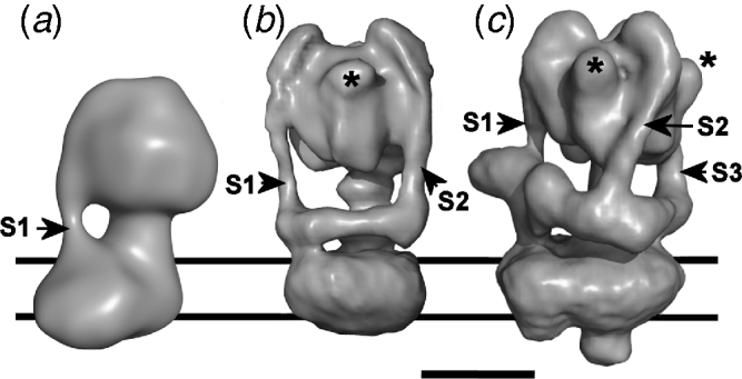
Although relatively low resolution, a comparison of yeast and bovine Fo regions also provides insight into the positions of some of the small supernumerary subunits associated with the mitochondrial complexes (Arnold et al. Reference Arnold, Pfeiffer, Neupert, Stuart and Schägger1998; Belogrudov et al. Reference Belogrudov, Tomich and Hatefi1996). Fo of the yeast preparation lacks subunits e (8·2 kDa) and g (11·3 kDa) and therefore has a mass ~15% smaller than its bovine counterpart. This correlates with the smaller volume of the yeast Fo (Lau et al. Reference Lau, Baker and Rubinstein2008). Difference maps suggest the location of these subunits in a lipid-exposed surface domain on the periphery of the integral membrane region of the F-ATPase stator. Positioning e and g adjacent to each other and to subunit b is consistent with co-purification, antibody labelling and cross-linking studies (Arnold et al. Reference Arnold, Pfeiffer, Neupert, Stuart and Schägger1998; Arselin et al. Reference Arselin, Giraud, Dautant, Vaillier, Brethes, Coulary-Salin, Schaeffer and Velours2003; Belogrudov et al. Reference Belogrudov, Tomich and Hatefi1996; Bustos & Velours, Reference Bustos and Velours2005; Soubannier et al. Reference Soubannier, Vaillier, Paumard, Coulary, Schaeffer and Velours2002). This Fo location suggests how they could be involved in dimerisation of the F-ATPase as part of the process of forming supramolecular complexes in the mitochondrial inner membrane (Devenish et al. Reference Devenish, Prescott and Rodgers2008; Minauro-Sanmiguel et al. Reference Minauro-Sanmiguel, Wilkens and García2005; Strauss et al. Reference Strauss, Hofhaus, Schröder and Kühlbrandt2008; Stuart, Reference Stuart2008). In a recently reported 3D reconstruction of the dimeric Saccharomyces mitochondrial F-ATPase (Couoh-Cardel et al. Reference Couoh-Cardel, Uribe-Carvajal, Wilkens and García-Trejo2010), interaction is mediated only via Fo–Fo surface contacts, with the region proposed to contain the a, b N-terminal region and the small e/g/i subunits interacting with the c-ring of the neighbouring complex. The interacting enzymes are arranged so that their long axes are angled at ~45° with respect to each other, consistent with a role for F-ATPase oligomerisation in curvature of mitochondrial cristae (Couoh-Cardel et al. Reference Couoh-Cardel, Uribe-Carvajal, Wilkens and García-Trejo2010).
5.2.2 The A-ATPase – a stator model with two stalks and a collar
A consistent feature of 3D reconstructions of A1Ao-ATPases is the presence of two peripheral stalks linking the catalytic and membrane domains (Fig. 5b). Reconstructions of complexes from the eubacterium T. thermophilus (Bernal & Stock, Reference Bernal and Stock2004) and the hyperthermophilic archaeon Pyrococcus furiosus (Vonck et al. Reference Vonck, Pisa, Morgner, Brutschy and Müller2009) at ~23 Å resolution show similar architecture. The two stators are ~120° apart and extend ~150 Å vertically downwards from the apex of A1. The first stator (labelled s1 in Fig. 5b) joins directly to the asymmetric density in Ao corresponding to the membrane domain of subunit a. The second (s2 in Fig. 5b) extends downwards to meet a ~100 Å long horizontal collar feature that extends at right angles from the point at which the first stalk merges with Ao. This collar is presumed to be the N-terminal domain of subunit a, comprising its first 330–350 residues, but has also been suggested to contain part of the A-ATPase homologue of V-ATPase subunit G (Coskun et al. Reference Coskun, Chaban, Lingl, Müller, Keegstra, Boekema and Grüber2004). Assuming density of 1·36 g/ml, the ~60 000 Å3 volume of this feature could certainly be filled by the 350 residues (42 kDa) of subunit a. The two stators appear equivalent in length, diameter and organisation, with both forming hooks over the apex of the A1 domain. The central axle can also be clearly seen in the Pyrococcus A-ATPase reconstruction (Vonck et al. Reference Vonck, Pisa, Morgner, Brutschy and Müller2009), which has asymmetric densities that may correspond to regions of subunit D not resolved in the (partial) crystal structure, or to subunit F. Spanning ~65 Å from the base of A1 to the upper surface of Ao, the axle is significantly longer than the equivalent structure in the F-ATPase (~30 Å), notwithstanding differences in the resolution of the reconstructions. A second prominent feature is the presence of 3 knob-like features projecting from the surface of the A1 domain, spaced ~120° apart (Fig. 5b). These features accommodate the ‘NHRs’ of subunit A.
An apparent connection between the stators across the apex of A1 in the reconstruction of Bernal & Stock (Reference Bernal and Stock2004) is absent from the cryo-EM reconstruction of the same T. thermophilus enzyme by Lau & Rubinstein (Reference Lau and Rubinstein2010), and may be an image-processing problem resulting from a scarcity of end-on views of the complex on negative stain grids. Although qualitatively quite similar to the reconstructions from negative stain data, the substantially improved resolution (to approximately 16 Å) of the native T. thermophilus complex imaged in ice has provided the first view of the internal anatomy of the complex. As in the F-ATPase, the axle penetrates almost the full length of the A1 domain and binds at its membrane-proximal end to a tri-lobed density that matches the A-ATPase subunit d homologue (Iwata et al. Reference Iwata, Imamura, Stambouli, Ikeda, Tamakoshi, Nagata, Makyio, Hankamer, Barber, Yoshida, Yokoyama and Iwata2004). As in reconstructions from negative stain data, two peripheral stalk components of the stator, spaced 120° apart, extend down from the apex of A1 to meet a horizontal collar. These ~160 Å long structures appear to have only a small degree of left-hand curvature. The cryo-EM data allow organisation of the integral membrane subunits a and c to be visualised for the first time, permitting some insights into the proton translocating apparatus. Perhaps surprisingly, there is minimal contact between a bi-lobed a subunit membrane domain and the external surface of the subunit c-ring (Lau & Rubinstein, Reference Lau and Rubinstein2010), reminiscent of a gramophone needle touching a vinyl record. This contact with the c-ring presumably includes TMH 5 and 6 that contain residues likely to be in involved in ion translocation, based on the similarities to the V- and F-ATPase a subunits discussed above. We also note that the reconstructions of A-ATPases by Bernal & Stock (Reference Bernal and Stock2004) and Vonck et al. (Reference Vonck, Pisa, Morgner, Brutschy and Müller2009) display the same apparent handedness, with the horizontal collar extending clockwise from its contact with Stator 1 when the complex is viewed end-on to the A1 domain. However, the absolute hand for these reconstructions was not determined. The alternative hand, shown for the Pyrococcus model in Fig. 5b, is consistent with the absolute hand determined for the T. thermophilus A-ATPase by Lau and Rubinstein using tilt pairs and the method of Rosenthal & Henderson (Reference Rosenthal and Henderson2003). We believe that this represents the correct hand for all A-ATPases, and the hand of the Pyrococcus A-ATPase reconstruction has been flipped in Fig. 5b to reflect this.
5.2.3 The V-ATPase – a stator model with three stalks and a collar
A consensus V-ATPase organisation has emerged only recently with improved 3D reconstructions. Yeast V-ATPase models generated from negative stain data (Diepholz et al. Reference Diepholz, Börsch and Böttcher2008a, Reference Diepholz, Venzke, Prinz, Batisse, Flörchinger, Rössle, Svergun, Böttcher and Féthièreb; Zhang et al. Reference Zhang, Zheng, Mazon, Milgrom, Kitagawa, Kish-Trier, Heck, Kane and Wilkens2008) and for the V-ATPase from M. sexta larvae in vitrified ice (Muench et al. Reference Muench, Huss, Song, Phillips, Wieczorek, Trinick and Harrison2009) show three peripheral stalks (Fig. 5c). These form part of a stator complex that is appreciably more elaborate than that of either F- or A-ATPases, with all three stalks connecting to a horizontal collar that extends ~250° around the mid-section of the complex, substantially further than the comparable A-ATPase structure. This collar ties all three stators to the subunit a density in Vo. The lower region of each stalk is angled between 10° and 25°, consistent with the direction of twisting of the rotor and stators driven by ATP hydrolysis (Fig. 1c). In addition to the three knob-like NHR structures seen in all reconstructions of A- and V-ATPases, two other prominent features are evident in the V-ATPase. A prominent ‘nose’ that protrudes ~40 Å from the end of the collar where it meets Stator 1 (Fig. 5c) is proposed to be subunit H, a subunit unique to eukaryotic V-ATPases. The second feature is a ~35 Å protrusion from the bottom of Vo (exposed to the lumen of the endomembrane compartment, or extracellular). This feature may be peculiar to plasma membrane-localised V-ATPases, being seen in the bovine clathrin-coated vesicle (Wilkens et al. Reference Wilkens, Vasilyeva and Forgac1999) and Manduca enzymes but not in those from the yeast vacuolar membrane (Diepholz et al. Reference Diepholz, Venzke, Prinz, Batisse, Flörchinger, Rössle, Svergun, Böttcher and Féthière2008b; Zhang et al. Reference Zhang, Zheng, Mazon, Milgrom, Kitagawa, Kish-Trier, Heck, Kane and Wilkens2008) or plant tonoplasts (Domgall et al. Reference Domgall, Venzke, Luttge, Ratajczak and Böttcher2002). This density has been assigned to the glycosylated accessory subunit Ac45 (Supek et al. Reference Supek, Supekova, Mandiyan, Pan, Nelson and Nelson1994; Wilkens et al. Reference Wilkens, Vasilyeva and Forgac1999), a polypeptide that associates with other Vo subunits in osteoclasts and appear to be involved in maintaining proton pumping activity (Feng et al. Reference Feng, Cheng, Pavlos, Yip, Carrello, Seeber, Eidne, Zheng and Xu2008). Although these observations support the assignment of Ac45 to this density, plasma membrane V-ATPases from epithelial cells are not recognised by antibodies to Ac45 (Supek et al. Reference Supek, Supekova, Mandiyan, Pan, Nelson and Nelson1994), casting some doubt on the idea. Moreover, although genes for Ac45 homologues are present in insects, mass spectrometric analysis of the Manduca V-ATPase has not revealed its presence (Huss & Wieczorek, Reference Huss and Wieczorek2007).
5.3 Do the rotary ATPase membrane domains contain ‘half channels'?
Is there any experimental evidence for the ‘half channels’ described in the Junge/Vik Brownian ratchet model (Junge et al. Reference Junge, Lill and Engelbrecht1997; Vik & Antonio, Reference Vik and Antonio1994), in any class of rotary ATPase? Site-directed labelling of the E. coli F-ATPase subunit a has shown that sites predicted to be part-way down TMHs are reactive to aqueous phase reagents, suggesting the existence of water-accessible pores and consistent therefore with the presence of channels (Angevine & Fillingame, Reference Angevine and Fillingame2003; Angevine et al. Reference Angevine, Herold, Vincent and Fillingame2007). Although no such data are available for the A- or V-ATPases, EM data do suggest the presence of pores. The reconstruction of the yeast Vo shows a pore-like depression on the lumenal/extracellular side (Wilkens & Forgac, Reference Wilkens and Forgac2001), and Diepholz et al. (Reference Diepholz, Börsch and Böttcher2008a, Reference Diepholz, Venzke, Prinz, Batisse, Flörchinger, Rössle, Svergun, Böttcher and Féthièreb) have proposed that accessibility of heavy metal stain to an interior cavity in Vo of the intact yeast V-ATPase suggests the presence of an aqueous pore. However, no pores are evident in cryo-EM models of A-ATPase or V-ATPase, and further structural and biochemical work will be needed to confirm their existence.
6. Fitting the pieces together – mosaic structures of the rotary ATPases
6.1 The structural model of the F-ATPase is almost complete
Recent 3D reconstructions from cryo-EM data and a wealth of supporting biochemical data, in particular, relating to subunit contacts, allow crystal structures of sub-complexes and individual component to be confidently fitted to give more complete models. This is particularly true of the mitochondrial F-ATPase, where there is extensive overlap between crystal structures for the yeast (αβ)3:γ:δm:c 10 (Stock et al. Reference Stock, Leslie and Walker1999; Dautant et al. Reference Dautant, Velours and Giraud2010), the almost entirely complete membrane extrinsic part of the bovine complex (Rees et al. Reference Rees, Leslie and Walker2009) and the b:d:F6:OSCP stator (Dickson et al. Reference Dickson, Silvester, Fearnley, Leslie and Walker2006). Optimal fitting of these structures to the cryo-EM reconstruction of the F-ATPase (Fig. 6a) requires removal of the inward curvature of the stator stalk which presumably occurs in the crystal structure of the membrane extrinsic region due to disconnection from the integral membrane segments of the b subunit (Rees et al. Reference Rees, Leslie and Walker2009). The stator tracks the non-catalytic αDP/βTP interface, making contacts exclusively with α at the apex of F1, but near both α and β as it passes across the surface of F1, consistent with cross-linking data (McLachlin et al. Reference Mclachlin, Coveny, Clark and Dunn2000). The areas of uncertainty are of course the membrane-embedded end of the stator comprising subunit a and the integral membrane region of subunit b. Crucially, lack of accurate structural models for this region limits our understanding of the organisation of the ion translocation pathway.
Mosaic models of the rotary ATPases. Crystal structures are fitted to the 3D EM models in Fig. 5. (a) Mitochondrial F-ATPase with F1-ATPase (pdb 2WSS) fitted, showing α and β subunits in blue and red, respectively. The b:d:F6 stator sub-complex (pdb 2CLY; yellow) was fitted by superimposing it onto the backbones of the corresponding (incomplete) subunits in the 2WSS structure, with the angle of the lower stator adjusted to fit the EM density. The OSCP density from 2WSS is yellow. Fitting of the E. coli c 10 ring model (pdb 1A91; green) was guided by the c-ring orientation in the yeast F1-c10 structure (pdb 1Q01) as in Lau et al. (Reference Lau, Baker and Rubinstein2008). (b) A-ATPase and (c) V-ATPase. Crystal structures fitted are the T. thermophilus (AB)3:D:F complex (pdb 3A5D; A, red; B, blue; D, pale green; F, pink), E:G heterodimer in either spacefill or ribbon mode (pdb 3K5B; yellow), subunit d (pdb 1R5Z; orange) and E. hirae decameric c-ring (pdb 2DB4; dark green). Crystal structures of C (pdb 1U7L; cyan) and H (pdb 1HO8) are also fitted to the collar of the V-ATPase. Fitting was performed using Chimera and optimised by eye to accommodate available cross-linking data. Two views, rotated by 180°, are shown for A- and V-type complexes. Membrane domain regions coloured red are those for which no structural data are available.

6.2 Mosaic models of the A- and V-ATPases
A- and V-ATPases models are incomplete mosaics, with positioning of subunit and sub-complex crystal structures supported only by low-resolution biochemical data (Fig. 6b, c). However the quantity of this supporting data and quality of crystal structure fitting at least makes general positioning of subunits unambiguous, if not their precise orientations or conformations. As in the F-ATPase, the greatest uncertainty is in the a subunit that forms part of the stator and ion-translocation apparatus. The (AB)3 and (AB)3:D:F complexes fit well into both A- and V-ATPase reconstructions, facilitated by locating the three subunit A NHRs into the obvious protrusions in the EM maps (Fig. 6b, c). The incomplete crystal structure of the D:F axle does not reach the d subunit in the membrane domain, but contact in the complete A-ATPase is inferred from cross-linking between the upper rim of d and the F subunit (Iwata et al. Reference Iwata, Imamura, Stambouli, Ikeda, Tamakoshi, Nagata, Makyio, Hankamer, Barber, Yoshida, Yokoyama and Iwata2004), an interaction almost certain to be conserved in the V-ATPase.
Fitting of the E:G stator sub-complex (Lee et al. Reference Lee, Stewart, Donohoe, Bernal and Stock2010a) into A- and V-ATPase maps results in almost complete filling of the stalks linking the catalytic and membrane domains (Fig. 6b, c). In the A-ATPase, this places the N-terminal regions of two copies of E:G in contact with opposite ends of the ~110 Å-long horizontal arm which, by elimination, is likely to contain the soluble N-terminal domain of subunit a (a N). The resulting interaction between a N and either Stator 1 or 2 (as designated in Fig. 5) would account for the L-shaped complex formed when the Enterococcus homologues of E, G and a N are co-expressed (Yamamoto et al. Reference Yamamoto, Unzai, Saijo, Ito, Mizutani, Suno-Ikeda, Yabuki-Miyata, Terada, Toyama, Shirouzu, Kobayashi, Kakinuma, Yamato, Yokoyama, Iwata and Murata2008). In the V-ATPase, cross-linking and protein interaction studies also indicate that both subunits E and G contact subunit a (Norgett et al. Reference Norgett, Borthwick, Al Lamki, Su, Smith and Karet2007; Qi & Forgac, Reference Qi and Forgac2008; Xu et al. Reference Xu, Vasilyeva and Forgac1999). There are clearly parallels between the A- and V-ATPases in terms of the connections between Stators 1 and 2 and the membrane domain. The contact between the C-terminal region of E and B that results from fitting of (AB)3:D:F and E:G crystal structures is consistent with the contacts mapped by NMR chemical shift experiments (Kish-Trier & Wilkens, Reference Kish-Trier and Wilkens2009b), but not with interactions with the A subunit detected fluorometrically (Biukovic et al. Reference Biukovic, Rossle, Gayen, Mu and Grüber2007).
In the A-ATPase model, the stator filaments descend from anchor points at the top of subunit B, but unlike in the F-ATPase, they do not follow the line of the non-catalytic subunit interface. Similar anchor points are evident in the V-ATPase, but the stators descend at an angle across the faces of the B subunits before crossing the lower regions of the non-catalytic A–B interfaces (Fig. 6c). Fitting of the E:G crystal structure suggests that the point at which the angle of each peripheral stalk changes corresponds to the flexion points suggested by Lee et al. (Reference Lee, Stewart, Donohoe, Bernal and Stock2010a). The position of E in the V-ATPase map is also consistent with chemical cross-linking to sites distributed across the surface of B (Arata et al. Reference Arata, Baleja and Forgac2002). According to this arrangement of the E:G sub-complex, the C-terminal domain of E forms the primary contact with B, with the coiled coil region suspended below this but contributing little or nothing to binding to B. A temperature-sensitive mutation is sited in this region of the yeast subunit E (Fig. 3a, b; Zhang et al. Reference Zhang, Parra, Liu and Kane1998), indicating that thermal stability of the fold of this domain underpins its crucial role as an intermolecular linker. At current resolution, the membrane domain of the A-ATPase can accommodate either a dodecamer of 2 TMH units (Lau & Rubinstein, Reference Lau and Rubinstein2010), or a decamer of 4 TMH units (Vonck et al. Reference Vonck, Pisa, Morgner, Brutschy and Müller2009)), but the decameric complex is the best fit to Vo (Muench et al. Reference Muench, Huss, Song, Phillips, Wieczorek, Trinick and Harrison2009).
Models of the A- and V-ATPases differ at the horizontal collar, which in V-type reconstructions link the three stators (Fig. 5c). By analogy to the A-ATPase, part of this structure (linking Stators 1 and 2) should be the subunit a N-terminal domain (a N: Fig. 1c), but this feature also accommodates the H and C subunits (Fig. 6c). The section of the collar between Stators 1 and 2 is thicker than in the A-ATPase and has a projecting ‘nose’. Positioning the H subunit crystal structure in this region, with its larger N-terminal domain within the nose, provides an excellent fit (Fig. 6c) and is consistent with data showing interaction with both subunit a (Diab et al. Reference Diab, Ohira, Liu, Cobb and Kane2009; Landolt-Marticorena et al. Reference Landolt-Marticorena, Williams, Correa, Chen and Manolson2000) and the N-terminal end of E (Lu et al. Reference Lu, Vergara, Zhang, Holliday, Aris and Gluck2002). Thus, H lies along the cytoplasmic surface of a N bound to Stator 1 (Fig. 8a). Subunit C is accommodated by the part of the horizontal collar linking Stators 2 and 3 (Fig. 6c), with its narrower ‘head’ in contact with Stator 3 and its broader ‘foot’ oriented towards Stator 2. Binding studies using truncated forms of C show that the ‘head’ region has a much greater affinity for E:G (Oot & Wilkens, Reference Oot and Wilkens2010). Contact with the N-terminal regions of E and G at the foot of these stator elements is also consistent with cross-linking and protein interaction data (Féthière et al. Reference Féthière, Venzke, Madden and Böttcher2005; Inoue & Forgac, Reference Inoue and Forgac2005; Jones et al. Reference Jones, Durose, Findlay and Harrison2005, Reference Jones, Durose, Phillips, Keen, Findlay and Harrison2010; Xu et al. Reference Xu, Vasilyeva and Forgac1999). A sub-complex comprising E, G and C adopts a similar L-shaped architecture to the A-ATPase E:G:a N complex discussed above (Diepholz et al. Reference Diepholz, Venzke, Prinz, Batisse, Flörchinger, Rössle, Svergun, Böttcher and Féthière2008b), although it is unclear whether this represents a Stator 2-subunit C or Stator 3-subunit C model (or a mixture of both). Either sub-complex would have to undergo some conformational rearrangement in order to fit the corresponding stator-collar density in reconstructions of the intact enzymes (Diepholz et al. Reference Diepholz, Venzke, Prinz, Batisse, Flörchinger, Rössle, Svergun, Böttcher and Féthière2008b; Lee et al. Reference Lee, Stewart, Donohoe, Bernal and Stock2010a). Stock and co-workers have pointed out that the V-ATPase subunit C is also an excellent fit to the horizontal arm that links the two stator stalks of the A-ATPase (Lee et al. Reference Lee, Stewart, Donohoe, Bernal and Stock2010a). Does this mean that the two sections of the stator collar in the V-ATPase are actually broadly equivalent parts of a quasi-symmetrical ‘wishbone’ feature?
7. Unexplained features and unresolved questions
There are clearly major differences between the three rotary ATPases, particularly in the number and nature of the stator connections and in the coupling between the axle and c-ring of the rotor. If one accepts that the archaeal A-ATPase is closest to a common ancestral rotary ATPase, then several questions arise: Why did the V-ATPase evolve a triple stator connection, when it appears that mechanically two are adequate for both ATP-driven ion pumping and ATP synthesis? Similarly, why did the F-ATPase move to a single stator connection and evolve a different axle/c-ring coupling system? Clues to these may come from a more detailed examination of mechanics and regulation. In this section, we examine some of the questions and unexplained features arising from the EM models.
7.1 Is the isolated V-ATPase in a ‘ground state’ conformation?
In the improved models of A- and V-ATPases, authors have noted conformational variability between the three sectors of the A1/V1 domain corresponding to each A:B catalytic unit (Bernal & Stock, Reference Bernal and Stock2004; Diepholz et al. Reference Diepholz, Börsch and Böttcher2008a, Reference Diepholz, Venzke, Prinz, Batisse, Flörchinger, Rössle, Svergun, Böttcher and Féthièreb; Lau & Rubinstein, Reference Lau and Rubinstein2010). We have also noted this in the cryo-EM model of the Manduca V-ATPase. A horizontal section through the model where the D:F axle emerges from V1 shows three densities corresponding to the bottom of each A subunit (Fig. 7a). The A:B interfaces closest to each of the three stators are non-catalytic. The A subunit adjacent to Stator 3 (s3) extends significantly further towards the membrane domain, suggesting that its conformation differs from that of the other two. By analogy to the F1 and A1 domain structures, it is likely that the two A:B units in similar conformations are those occupied by nucleotide ((AB)DP and (AB)TP in Fig. 7a), while the subunit extending closest to the membrane domain will be AE, with its extended, open conformation (Diepholz et al. Reference Diepholz, Börsch and Böttcher2008a).
Is purified V-ATPase in a homogeneous ‘ground state'? (a) Left: lower surface of V1 of the Manduca V-ATPase, viewed from the membrane. Locations of the three stator elements are indicated by s1–s3. The three densities radiating from the central axle represent the C-terminal domains of the three A subunits. The mass around s1 represents a section through part of the collar feature likely to contain the H subunit. Right: speculative arrangement of nucleotide-binding states of the active sites in V1. Each A/B constitutes a catalytic unit, with the nucleotide-binding status of the active site at each A/B interface indicated by E (‘empty’), DP (ADP and phosphate bound) or TP (ATP bound). D/F represents the axle of the V1 motor. The convex face of the curved subunit D coiled-coil points towards the (AB)E site, indicated by the arrow, with the C-terminal domain of F closest to ATP/BDP (consistent with Numoto et al. Reference Numoto, Hasegawa, Takeda and Miki2009). Such a resting state ensures proximity of F to H, as discussed in the main text. ATP turnover would drive counter-clockwise rotation of the axle. 3D reconstructions of both (b) the Manduca and (c) Saccharomyces V-ATPases show apparent contact between the collar/Stator 3 (s3) junction and the d/c-ring region of the rotor (arrowed). In (b), a vertical section is shown to reveal fitting of the c-ring and subunit d as in Fig. 6. The dashed line represents the plane of the section shown in (a).

Since reconstruction involves classification and averaging of equivalent views, the presence of different A/B conformational states is indicative of two things: firstly, it is clear that the majority of particles in each EM dataset used to generate the 3D reconstructions of V-ATPases (and A-ATPases) must be in the same conformational state. Subtle differences in their catalytic domains could not be visualised without highly homogeneous specimen. The corollary of this is that, in the absence of ATP or membrane potential, the great majority of ATPases on the EM grid are in a single, stable ‘ground state’. A second point is that the nucleotide occupancy of the three catalytic sites is likely to be different. In the T. thermophilus (AB)3 crystal structure, all three active sites are in equivalent ‘open’ unoccupied states (Maher et al. Reference Maher, Akimoto, Iwata, Nagata, Hori, Yoshida, Yokoyama, Iwata and Yokoyama2009), but in the A1 domain (AB)3:D:F crystal structure the presence of bound nucleotide correlates with asymmetry between the catalytic units and different interactions with the D:F axle (Numoto et al. Reference Numoto, Hasegawa, Takeda and Miki2009). As in F1-ATPase crystal structures, curvature of the lower region of the axle in the A1 crystal structure points towards the ‘empty’ active site (AE/BE in Fig. 7a), with the major part of the F subunit sitting at the foot of the subunit D axle, below its concave surface and oriented closest to the ATP/BDP non-catalytic interface (Numoto et al. Reference Numoto, Hasegawa, Takeda and Miki2009) (Fig. 7a).
Matching the asymmetry in the A1 (and F1) crystal structure with that of the V-ATPase model allows us to determine the likely orientation of the D:F axle in the ‘ground state’ V-ATPase. From the orientation of axle subunits with respect to the AE subunit in the A1 structure, the concave face of D and F should face towards Stator 1 and the H subunit (Fig. 7a). Does this particular axle orientation have any significance? A uniform resting state may precede (and be a requirement for) the reversible domain dissociation that controls activity of some V-ATPases (Diepholz et al. Reference Diepholz, Börsch and Böttcher2008a, and discussed in the next section). In this case, the proposed axle orientation in the ‘ground state’ would mean that only minimal movement of subunit H would be required to bring about the contact with subunit F that occurs upon detachment and inactivation of the V1 domain (Jefferies & Forgac, Reference Jefferies and Forgac2008). In the context of the structure of the membrane-extrinsic part of the F-ATPase, Rees et al. (Reference Rees, Leslie and Walker2009) have also noted that the high degree of order in the crystals suggests a single predominant motor–stator conformation. However, fluorometric measurements of rotational movement in real time show that the F-ATPase rotor comes to rest in any one of three possible angular positions in the absence of nucleotide, or if catalytically ‘frozen’ by adding AMP-PNP (Zimmermann et al. Reference Zimmermann, Diez, Zarrabi, Gräber and Börsch2005). This intrinsic heterogeneity may undermine attempts to achieve higher resolution EM reconstructions of the F-ATPase.
An anomaly of the V-ATPase models is that the region where Stator 3 joins the horizontal collar structure is apparently also in contact with the axle of the rotor, evident in both the Manduca (Fig. 7b) and Saccharomyces (Fig. 7c) enzymes from cryo-EM and negative stain data, respectively. This places the N-terminal ends of the E and G subunits of Stator 3 close to the upper rim of the c-ring and its subunit d plug (Fig. 7b). Although this contact is consistent with interaction between subunits G and d in vitro (Rishikesan et al. Reference Rishikesan, Gayen, Thaker, Vivekanandan, Manimekalai, Yau, Shochat and Grüber2009), it clearly makes little sense mechanically since it ties together the rotor and stator parts of the motor. This potentially inhibitory contact may also reflect the existence of an inactive ground state in the purified V-ATPase, perhaps in response to the absence of substrate. Analysis of the complex trapped in catalytically active states may be needed to resolve this issue.
7.2 Is stator complexity linked to regulation?
A feature that distinguishes the V-ATPase from its A- and F-type cousins is sensitivity to low-energy status. In some cells, V-ATPases are major consumers of ATP, resulting in a strong need to switch off when ATP is low. This occurs via rapid and reversible detachment of V1 from the membrane domain, a process that appears to be mediated via collar subunit C, and effected by subunit H. It is now possible to add more details to this mechanism while remaining consistent with available biochemical data. In active enzyme, H lies on top of the collar region presumed to be the N-terminal domain of subunit a (a N) that links Stators 1 and 2 (Fig. 8a). In addition to a N contacts, H also binds one or both of the α-helices of the E:G complex in Stator 1, perhaps via a groove that runs across its surface (Fig. 8b). Destabilisation of the C-subunit (as a result of, for example, phosphorylation) would in turn destabilise the a N:C:H collar, causing the a N domain to detach from H and the ends of Stators 1 and 2. Subunit H, no longer constrained by its association with a N but still tethered to Stator 1, can change position such that its C-terminal domain binds to subunit F of the rotor (Diab et al. Reference Diab, Ohira, Liu, Cobb and Kane2009; Jefferies & Forgac, Reference Jefferies and Forgac2008). This could involve rotation of the entire H subunit about Stator 1 by ~30° (Fig. 8b), which would apply torsion to the Stator 1 coiled-coil. Alternatively, the C-terminal domain of H alone could move, rotating about a flexible inter-domain linker. Locking the position of the rotor would have the effect of inhibiting catalytic cycling in (AB)3, preventing futile ATP consumption. Relocation of a N in Vo may also play a role in blocking the passive H+ flow that would collapse any membrane potential, as discussed at the end of Section 5.1.
Inactivation of V-ATPase by relocation of subunit H. (a) Superimposed models of the Pyrococcus furiosus A-ATPase (EMD-1542) and Manduca V-ATPase (EMD-1590) are shown as surface and mesh, respectively. In the V-ATPase model, additional density in the region of the horizontal collar that links Stators 1 and 2 (s1 and s2) accommodates subunit H (magenta: pdb 1ho8), with its larger N-terminal domain fitting into the projecting ‘nose’ of the collar and its C-terminal domain closest to Stator 2. In both A- and V-ATPases, this collar contains the N-terminal domain of subunit a (a N). One end of subunit C (cyan: pdb 1u7l), fitted to the region of the collar linking Stator 2 to Stator 3, is also visible. (b) Model for inhibition of ATP turnover by V1. The figure shows a horizontal section through the collar region of the Manduca model (grey mesh), viewed from the membrane domain. In the intact enzyme, subunit H (magenta) is constrained by contacts with a N and is attached to Stator 1, perhaps via contacts across a groove on its surface. In the detached V1 domain, H (grey) is no longer constrained by a N, allowing it to rotate about its connection to Stator 1 (described by the curved arrow). Contact between the H C-terminal domain and the D:F axle prevents rotation and inhibits ATP turnover. Rotation of H by ~30° would bring it into direct contact with the axle. The residue shown in cyan is the location of the S381C mutation that cross-links to F in the detached yeast V1.

Diepholz et al. (Reference Diepholz, Börsch and Böttcher2008a) argue that the complementarity needed to ensure efficient re-association of V1 and Vo requires a uniform V1 conformation prior to separation, or a switching mechanism that confers uniformity post-separation. According to the model in Fig. 7 and discussed above, in this conformation ATP- and ADP-occupied sites will be oriented closest to Stators 1 and 2, respectively. Controlled dissociation also requires turnover of ATP (Huss & Wieczorek, Reference Huss and Wieczorek2007), consistent with the idea that a limited number of catalytic steps is sufficient to drive all ATPases in the population into the single conformation state that permits dissociation. Such a state would ensure a uniform resting position for the D:F axle, hence the observed proximity of F to H in detached V1 (Jefferies & Forgac, Reference Jefferies and Forgac2008) (Fig. 8b).
The role of subunits C and H in regulatory dissociation argues that evolution (or retention?) of three stator linkages in the eukaryotic V-ATPases is an adaptation allowing incorporation of additional regulatory features into the progenitor complex that presumably most closely resembled the ‘2-stalk stator’ A-ATPase. It follows that if disconnection of Stator 3 from the network as a result of loss of subunit C is sufficient to completely destabilise V1–Vo interaction, then the Stator 1 and Stator 2 linkages in the V-ATPase must be significantly weaker than the corresponding contacts in the A-ATPase, since the archaeal enzyme operates with only these two. The predominance of the Stator 3-subunit C contact in maintaining stator organisation in the V-ATPase fits with the high affinity between E:G and the subunit C ‘head’ reported by Oot & Wilkens (Reference Oot and Wilkens2010).
7.3 The motor asymmetry question
One of the most striking features of rotary ATPases is asymmetry between their ATPase and ion pump functions. Based on the stoichiometry of subunits in the catalytic domains and c-rings, a ‘3-stroke’ ATPase may drive (or be energised by) 10–15 ion translocation events. Thus, the number of events linked to each 120° step (with 80°/40° sub-steps) in the catalytic domain can be non-integer. This also implies a non-integer H+(Na+)/ATP ratio for the coupled membrane that contains the ATPase, although measurements based purely on thermodynamics of ATP synthesis and its energising membrane potential suggest that this may not necessarily be the case (Steigmiller et al. Reference Steigmiller, Turina and Gräber2008). In linear motors such as myosin, each ATP turnover is linked to a single power stroke that stems from a large conformational change, typically generating a force of magnitude ~5 pN. In rotary ATPases, with non-integer H+/ATP ratios, such a direct coupling is unlikely. Instead, a model involving some form of ‘energy buffering’ between the coupled motors is required which also does not compromise the extremely high efficiency of energy transfer. An elastic power transmission model has been proposed in which deformation of one or more flexible component buffers torque transmission (Cherepanov et al. Reference Cherepanov, Mulkidjanian and Junge1999; Junge et al. Reference Junge, Sielaff and Engelbrecht2009). This type of coupling is consistent with the smooth movement of the c-ring observed at low substrate concentrations. An advantage of this model is that it can accommodate the different c-ring stoichiometries. However, it does require an elastic component that presumably has a homologue in all rotary ATPases, since stoichiometry mismatch appears widespread.
7.3.1 Power transmission in the F-ATPase
Theoretical modelling and experiments on the F-ATPase have led to different proposals for this elastic element. These include the γ subunit left-handed coiled-coil (Capaldi et al. Reference Capaldi, Schulenberg, Murray and Aggeler2000), the peripheral stalk of the stator, and the β-sheet region of the β subunit that acts as a hinge to allow the lever movement of the C-terminal helical region (Sun et al. Reference Sun, Chandler, Dinner and Oster2003). A role for winding/unwinding of γ in power transmission is supported by the shortening of F-ATPase particles observed by EM when Mg2+ and AMP-PNP are added (Capaldi et al. Reference Capaldi, Schulenberg, Murray and Aggeler2000). Flexibility of the stator stalk component is suggested by its curvature in reconstructions that appears to be compliant with the direction of rotation during ATP synthesis (Rubinstein et al. Reference Rubinstein, Walker and Henderson2003) (Fig. 1b). However, several lines of evidence argue against stator elasticity. Firstly, in the mitochondrial stator, subunit b is reinforced by OSCP, d and F6, suggesting a rigid structure (Fig. 3d). Potentially flexible points in the structure identified by Rees et al. (Reference Rees, Leslie and Walker2009) (Fig. 3c) may not signify elasticity for the stator as a whole, but may instead allow flexing to accommodate catalytically driven conformational changes in the (αβ)3 motor. Alternatively, applying force in a direction normal to the external surface of the c-ring may be important in maintaining its contact with subunit a. Even in the case of the bacterial stator, where the ability of subunit b to tolerate mutational additions or deletions implies flexibility (Sorgen et al. Reference Sorgen, Caviston, Perry and Cain1998, Reference Sorgen, Bubb and Cain1999), the implied side-to-side alignment of α-helices in the b dimer would restrict flexing, limiting its ability to contribute to power transmission. Secondly, compliance measurements indicate that the F-ATPase stator overall is relatively rigid, as is the γ subunit coiled-coil (Sielaff et al. Reference Sielaff, Rennekamp, Wächter, Xie, Hilbers, Feldbauer, Dunn, Engelbrecht and Junge2008b). The region of the rotor comprising the γ/δm/εm ‘foot’ and c-ring extramembranous loops was identified as the most elastic and likely therefore to play a role in power transmission. An elastic power transmission model for the F-ATPase involving contributions from the β subunit hinge and rotor foot regions (but not the stator) therefore seems the most plausible.
7.3.2 Power transmission in the V- and A-ATPases
Can the same model be applied to V- and A-ATPases, or do the major differences in stator complexity and axle/c-ring coupling suggest a different mechanism? The currently unresolved ‘foot’ region of subunit D will be significantly smaller than its F-ATPase counterpart (<76 residues), and the A-ATPase homologue of d is a relatively compact structure, likely to be constrained by multiple contacts with the internal surface of the c-ring and axle. Neither is likely therefore to be functionally equivalent to the elastic components of the F-ATPase. Could the E:G stator elements contribute to power transmission? As with the F-ATPase b subunit, functionality of mutational insertions into subunit G implies tolerance of variations in length of this stator component (Charsky et al. Reference Charsky, Schumann and Kane2000). However, molecular dynamics simulations and normal mode analysis indicate that α-helical coiled coils are very stiff for stretching, and somewhat less so for bending (Adamovic et al. Reference Adamovic, Mijailovich and Karplus2008). The deformation energy associated with a ~150 Å-long stator coiled coil with hendecad/quindecad repeat such as in E:G (<3·1 k BT nm−1) (Lee et al. Reference Lee, Stewart, Donohoe, Bernal and Stock2010a) would be ~2× the energy associated with hydrolysis of each ATP molecule (Wolgemuth & Sun, Reference Wolgemuth and Sun2006). Thus, it appears that in the A-/V-ATPase, the peripheral stalk components of the stator are relatively rigid. The structures contributing to elastic power transmission in these ATPases therefore remain unclear.
We can speculate about the evolutionary drivers for divergence in stator organisation in all three ATPases. In the eukaryotes, retention of three peripheral stalks of similar structure to those in A-ATPases facilitated incorporation of a regulatory system into the stator of the rotary motor that allowed activity to be linked to the energetic status of the cell. F-ATPases from both bacteria and organelles adapted differently, reinforcing the single remaining stator (albeit by different means). F-ATPases appear to operate with a higher average rotor torque than either the A- or V-ATPases, so this may be an adaptation in response to a need for greater mechanical robustness. This could also be the driving force for changes to the rotor/c-ring coupling.
8. Future directions
The last dozen years or so have revolutionised understanding of rotary ATPases. The direct demonstration of rotary motion during ATP hydrolysis has now evolved into simultaneous observation of rotation and changes in catalytic conformation or substrate/product turnover (Masaike et al. Reference Masaike, Koyama-Horibe, Oiwa, Yoshida and Nishizaka2008; Nishizaka, Reference Nishizaka2004). Understanding of the structures of F1 in different states, peripheral stator components and c-ring parts has also developed. Notwithstanding difficulties in correlating F1-ATPase crystal structures with catalytic states determined biophysically (Okuno et al. Reference Okuno, Fujisawa, Iino, Hirono-Hara, Imamura and Noji2008; Sielaff et al. Reference Sielaff, Rennekamp, Engelbrecht and Junge2008a), this has led to much more detailed models of the F1-ATPase mechanism, although grey areas remain. Within the last year, the first A-ATPase sub-complex structures have become available. Recent history has shown that accurate, experimentally verifiable models of transport processes emerge when complete high resolution structures become available (Vinothkumar & Henderson, Reference Vinothkumar and Henderson2010). A key area of focus over the next few years must be the structure and function of the ion pump part of the rotary ATPases in order to understand membrane potential-powered ATP synthesis. We can anticipate that complete high resolution structures for the rotary ATPases will lead to verifiable models of proton pumping in Ao and Vo, and torque generation by the Fo electromotor. This may help reveal the basis for apparently variable H+/ATP ratios and different gearing ratios shown by members of the rotary ATPase family.
To date, the primary role of EM in the study of the rotary ATPases has been to provide a low-resolution overview of organisation of the complexes, and to put crystal structures of sub-complexes and biochemical data into macromolecular context. However, despite enormous progress on the high resolution structures of extramembranous parts of the ATPases, EM has provided what is still the only insight into the structure of the crucial subunit a/c-ring interface (Lau & Rubinstein, Reference Lau and Rubinstein2010). In the absence of complete crystal structures, improved resolution of cryo-EM models should provide further insight into structure–function relationships in the proton pumps. Even for these relatively small, asymmetrical objects, the sub-10 Å resolution that will allow secondary structure to be seen is already feasible, although not technically trivial (Henderson, Reference Henderson2004). One of the most exciting applications for EM is time-resolved cryo-EM, allowing determination of natural conformations trapped <10 ms after introduction of substrates or inhibitors (Berriman & Unwin, Reference Berriman and Unwin1994; White et al. Reference White, Thirumurugan, Walker and Trinick2003). This approach has already proved successful when applied to the analysis of conformational states of linear motors. Supported by computational methods that allow multiple conformers to be determined from single large datasets (Elad et al. Reference Elad, Clare, Saibil and Orlova2008; Penczek et al. Reference Penczek, Chao, Frank and Spahn2006; Scheres et al. Reference Scheres, Gao, Valle, Herman, Eggermont, Frank and Carazo2006), this approach has the potential to demonstrate directly the structural changes that would allow discrimination between different models of power transmission. A temporal sequence of conformational states can provide constraints for mechanical simulations beyond the microsecond time domain that represents the current practical limit of molecular dynamics simulations.
The rotary ATPases are highly efficient energy conversion machines that have the remarkable ability to link the chemical and electrical energy on which life depends. The evolutionary processes that coupled together two essentially autonomous ancestral motors to give these energy converters has included revisions and adaptations that give specialisations adapted to work under particular physiological conditions and environmental pressures. With recent complete and accurate 3D models of all three rotary ATPases, we can start to draw direct comparisons between their structure/function relationships. In terms of the overall architecture of the complexes, knowledge of the A- and V-ATPases has certainly caught up with the F-ATPase, although this is not yet supported by the same wealth of functional, mechanistic and high resolution structural data. It seems clear that the additional complexity of the V-ATPase allows relatively sophisticated regulation. Where synthase and ion pump functions are represented by a single structural type, as in the A-ATPase, adaptation that maximises operational efficiency in a particular direction may be solely to do with the type of rotor ring subunit it employs. The big challenges are to see the workings of the ion translocation apparatus at atomic resolution and to characterise the mechanical changes that occur in asymmetrically coupled operation.
9. Acknowledgements
We are grateful to Janet Vonck for providing the Pyrococcus A-ATPase reconstruction prior to database release, and to Helmut Wieczorek and Markus Huss for comments on the manuscript. Work in the laboratories of M. A. H. and J. T. was supported by the UK BBSRC (BB/D016142). S. P. M. has an MRC Career Development fellowship.