1 Introduction
Vortex rings are simple but surprisingly intriguing vortical structures that are associated with understanding many fundamental and applied topics in the area of fluid dynamics research. Considered by many to be the ‘building block’ that underpins several important flow phenomena such as free, synthetic and impinging jets, the study of vortex-ring behaviour is also directly relevant towards a greater understanding of more complex real-world flows. These include jet engine start-ups, jellyfish/squid propulsion, the microburst phenomenon and volcanic eruptions, just to name a few. Much effort has gone towards understanding vortex-ring behaviour, be it under isolated conditions (i.e. free vortex rings), mutual collisions or solid surface impingement conditions. Significant importance has been attached to the basic structure and dynamics of vortex rings, subjected to systematic variations in their Reynolds numbers, formation numbers (Gharib, Rambod & Shariff Reference Gharib, Rambod and Shariff1998; Mohseni, Ran & Colonius Reference Mohseni, Ran and Colonius2001; Krueger, Dabiri & Gharib Reference Krueger, Dabiri and Gharib2006; Kaplanski et al. Reference Kaplanski, Sazhin, Fukumoto, Steven and Heikal2009), the stroke length, velocity program (Maxworthy Reference Maxworthy1972; Didden Reference Didden1979; Glezer Reference Glezer1988), as well as the orifice geometry used to produce them (Afanasyev Reference Afanasyev2006; Yu et al. Reference Yu, Ai, Gao and Law2008; Gao & Yu Reference Gao and Yu2010). In particular, there is also a strong interest in how vortex rings interact with solid boundaries, such as flat surfaces (Walker et al. Reference Walker, Smith, Cerra and Doligalski1987; Lim Reference Lim1989; Orlandi Reference Orlandi1990; Lim, Nickels & Chong Reference Lim, Nickels and Chong1991; Orlandi & Verzicco Reference Orlandi and Verzicco1993; Verzicco & Orlandi Reference Verzicco and Orlandi1994; Chu, Wang & Chang Reference Chu, Wang and Chang1995; Swearingen, Crouch & Handler Reference Swearingen, Crouch and Handler1995; Fabris, Liepmann & Marcus Reference Fabris, Liepmann and Marcus1996; Sullivan et al. Reference Sullivan, Niemela, Hershberger, Bolster and Donnelly2008; Cheng, Lou & Luo Reference Cheng, Lou and Luo2010; Couch & Krueger Reference Couch and Krueger2011; New, Shi & Zang Reference New, Shi and Zang2016) and curved surfaces (Homa, Lucas & Rockwell Reference Homa, Lucas and Rockwell1988; Orlandi Reference Orlandi1993; Naitoh, Sun & Yamada Reference Naitoh, Sun and Yamada1995; Verzicco et al. Reference Verzicco, Flor, Van Heijst and Orlandi1995; Ren, Zhang & Guan Reference Ren, Zhang and Guan2015), just to name a few. It should also be mentioned that vortex-ring interactions with flat surfaces are closely related to vortex pairs in ground effects as well (Harris & Williamson Reference Harris and Williamson2012; Leweke, Le Dizés & Williamson Reference Leweke, Le Dizés and Williamson2016).
Collisions of vortex rings upon different surface types are of direct relevance to jet-impingement-based heat transfer applications, be it for cooling or heating purposes. Since most cooling and heating applications involve the use of planar surfaces, substantial research had naturally focused on jet (and vortex-ring) impingements upon non-inclined and inclined flat surfaces, as mentioned earlier. On the other hand, jet and vortex-ring impingements upon curved surfaces had received comparatively less attention. From earlier studies (Gau & Chung Reference Gau and Chung1991; McDaniel & Webb Reference McDaniel and Webb2000; Cornaro et al. Reference Cornaro, Fleischer, Rounds and Goldstein2001; Chan et al. Reference Chan, Leung, Jambunathan, Ashforth-Frost, Zhou and Liu2002; Sharif & Mothe Reference Sharif and Mothe2010; Yang, Wei & Wang Reference Yang, Wei and Wang2011; Öztekin, Aydin & Avcı Reference Öztekin, Aydin and Avcı2013; Singh, Premachandran & Kohli Reference Singh, Premachandran and Kohli2013; Long & New Reference Long and New2015; New & Long Reference New and Long2015), it is quite clear that cooling or heating curved surfaces via impinging jets presents significant challenges, especially in terms of trying to achieve uniform cooling or heating effects. Hence, to address fundamental interests and to shed light on how to improve the heat transfer characteristics associated with vortex-ring collision with curved surfaces, several experimental and numerical studies had previously been conducted by Homa et al. (Reference Homa, Lucas and Rockwell1988), Naitoh et al. (Reference Naitoh, Sun and Yamada1995), Verzicco et al. (Reference Verzicco, Flor, Van Heijst and Orlandi1995), and more recently by Ren et al. (Reference Ren, Zhang and Guan2015), to look into the dynamics underlying collisions between circular vortex rings and round cylinders.
In the experimental study conducted by Homa et al. (Reference Homa, Lucas and Rockwell1988), they observed the formation of a secondary vortex pair when low-Reynolds-number vortex rings (i.e.
 $Re=165$
and 247) collide with round cylinders of very small diameter. In particular, the behaviour of the secondary vortex pair was found to be highly sensitive to any physical offset between the vortex-ring axis and the cylinder axis. However, it should be noted that the width of the nozzle that produced the vortex ring was approximately 7.6 and 46 times the diameters of the two round test cylinders and, as such, the observations are unique for large to very large vortex-ring-to-cylinder diameter ratios. Some of these observations were later confirmed by Naitoh et al. (Reference Naitoh, Sun and Yamada1995) when they performed smoke visualizations on vortex rings colliding with small round cylinders. In this case however, test cylinders with nozzle-to-cylinder diameter ratios ranging from 6.7 to 800 were used. Interestingly, they observed that the circular vortex ring behaves like an elliptic vortex ring, exhibiting an axis-switching phenomenon when the nozzle-to-cylinder diameter ratio was 40. Their experimental evidence indicates that formation and ejection of the secondary vortices during the collision process are responsible for such an intriguing observation.
Orlandi (Reference Orlandi1993) and Verzicco et al. (Reference Verzicco, Flor, Van Heijst and Orlandi1995) conducted experimental and numerical studies on the collisions of nominally two-dimensional vortex dipoles upon round cylinders as well. It has to be highlighted that the vortex dipoles were produced by the collapse of a three-dimensional turbulent jet in a stratified fluid, rather than the conventional cylindrical ‘slug’ flow techniques used in most vortex-ring studies. Despite this, however, certain aspects of the vortical behaviour associated with the collision along the cylindrical convex surfaces remain comparable. For instance, the formation of secondary vortex structures along the convex surface after the collision occurs was observed, even though the two-dimensional nature of the vortex dipole in the numerical simulations and experiments limited three-dimensional flows. Equally important, these studies made use of round cylinders that were comparable in size to the vortex dipoles, which set them apart from some of the earlier studies. More recently, Ren et al. (Reference Ren, Zhang and Guan2015) provided a detailed look into the vortex dynamics of a vortex ring colliding with a round cylinder with a diameter ratio (i.e. cylinder to vortex ring) of 0.5 in their numerical simulations. Their results show the non-uniform formation of a secondary vortex ring after the collision and its significant interactions with the primary vortex ring, resulting in highly intricate flow patterns and the formation of hair-pin vortices. However, the high vortex-ring Reynolds number (i.e.
 $Re=40\,000$
) used in that study also means that flow dynamics progress at such a rapid rate that isolating the exact vortical evolutions, not to mention the key flow mechanisms, proves to be challenging.
Nevertheless, it is clear that these preceding investigations have provided tantalizing hints of highly intricate and interesting flow physics underpinning vortex-ring collisions with round cylinders, and the present study is motivated by the need to clarify the fundamental flow physics further. In particular, our primary interest is in the collision of vortex rings upon round cylinders with diameters equal to or larger than the vortex-ring diameter, as is the case for some jet-impingement-based heat transfer applications. Some of the questions that we seek to address in the present study are: firstly, what are the effects on the vortex-ring collision behaviour when the curved cylindrical surface deviates further and further away from the usual flat-surface configuration? Secondly, are there strong relationships between the curvature of the cylindrical surface and the resulting changes in the vortex dynamics? Thirdly, and lastly, what are the dominant flow mechanisms that drive these changes in the vortex dynamics? In seeking the answers to these questions, a detailed experimental study based on laser-induced fluorescence (LIF) and time-resolved particle-image velocimetry (TR-PIV) has been conducted on vortex-ring collisions upon round cylinders here.
2 Experimental set-up
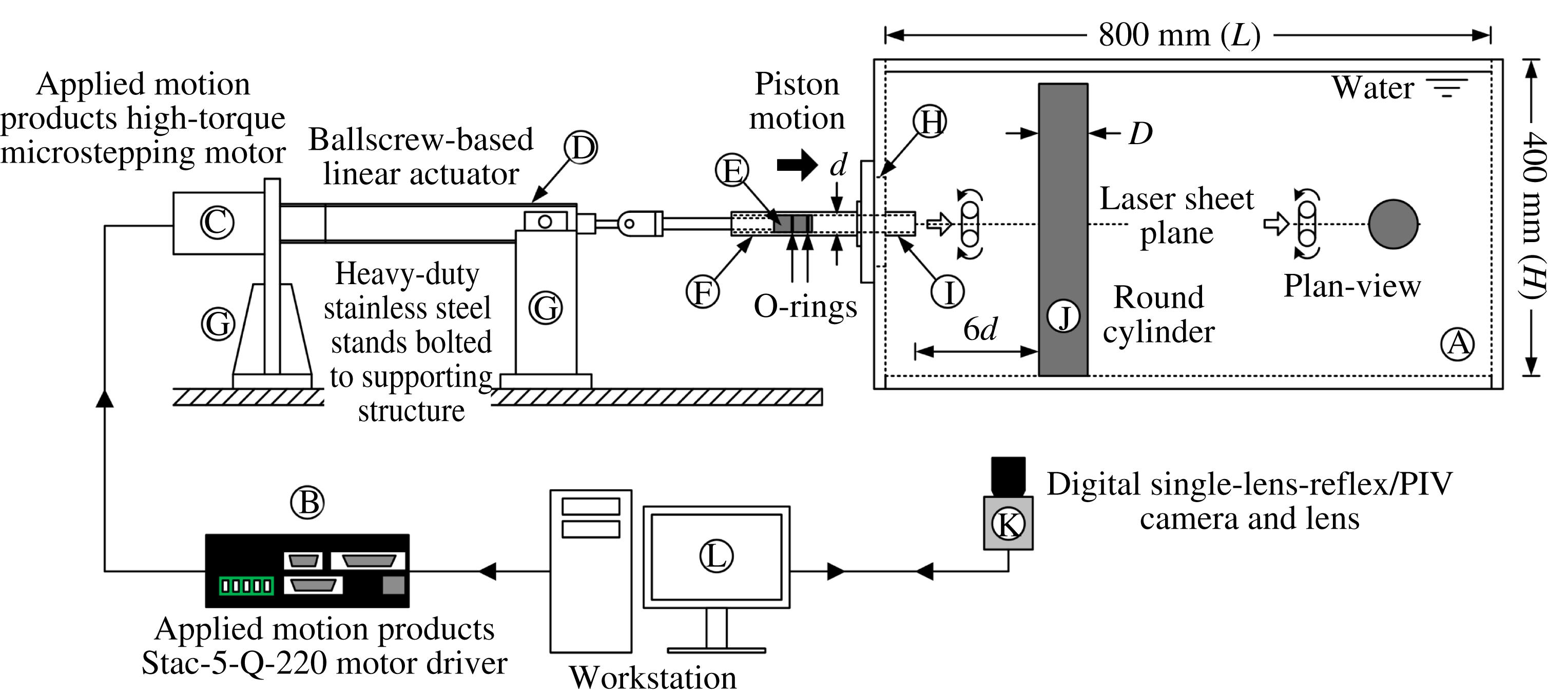
All experiments were performed in a horizontal and open free-surface type Plexiglas water tank (A) with internal working dimensions of 400 mm (W)
 $\times$
400 mm (H)
 $\times$
800 mm (L), as shown in figure 1. To produce the discrete vortex rings, an Applied Motion Products STAC-5 micro-stepping motor driver (B) was used to control an Applied Motion Products 5034-350 high-torque micro-stepping motor (C). A micro-stepping ratio of 51 200 steps per revolution was used in all experiments to ensure smooth generation of vortex rings. The motor was connected to a 10 mm pitch ball-screw-based linear actuator (D), which in turn was attached to a Delrin piston (E) located within a round hollow stainless steel tube of 20 mm internal diameter (F). Due to the sudden impulses produced during the vortex-ring generation, the linear actuator was bolted rigidly onto the supporting structure using heavy-duty stainless steel stands (G). The stainless steel tube was bolted onto a round Plexiglas plug (H) which was then fitted flushed into a 100 mm diameter round opening located at the centre of one water tank wall. The internals of the Plexiglas plug were designed such that it has an internal diameter of 20 mm and allowed circumferential release of fluorescent dye through the use of a built-in cylindrical dye port, similar to the design used by Lim, New & Luo (Reference Lim, New and Luo2001) and New (Reference New2009) previously. Lastly, a
 $d=20$
mm diameter, 30 mm long round nozzle (I) was attached to the exit of the round Plexiglas plug to minimize the effects of the water tank wall on the formation of the vortex rings. Note that the nozzle wall thickness was 1 mm and the nozzle exit was configured as a straight cut (i.e. perpendicular to the nozzle axisymmetric axis).
Schematics of the piston-based vortex-ring generator and experimental set-up.

All vortex rings were produced via the ‘cylindrical slug’ technique, whereby the piston imparted a sudden impulse that followed a preprogrammed trapezoidal velocity profile to the water (New et al.
Reference New, Shi and Zang2016). Vortex-ring Reynolds number was kept at
 $Re=Ud/\unicode[STIX]{x1D708}=4000$
, where
 $U$
and
 $\unicode[STIX]{x1D708}$
are the mean piston velocity and water kinematic viscosity, respectively. Note that the present trapezoidal profile produced a maximum and a mean piston velocity of 0.3
 $\text{m}~\text{s}^{-1}$
and 0.2
 $\text{m}~\text{s}^{-1}$
, respectively. Stroke length was also maintained at
 $L=30$
mm, such that the stroke ratio of
 $L/d=1.5$
was significantly lower than the critical stroke ratio of 3.6 that would produce a trailing jet aft of the vortex ring (Gharib et al.
Reference Gharib, Rambod and Shariff1998). Three different round cylinders (J) of diameter
 $D=20$
mm, 40 mm and 80 mm were used in the present study, such that they provided cylinder-to-vortex-ring diameter ratios of
 $D/d=1$
, 2 and 4, respectively. They were fabricated from Plexiglas and wrapped with matt black, thin adhesive paper to minimize laser light scatter during the experiments. Furthermore, the cylinders were carefully positioned such that their longitudinal axes were aligned with the vortex-ring axis for maximum flow symmetry, and that their cylindrical surfaces were maintained at a distance of
 $6d$
away from the nozzle exit.
Flow visualizations comprised of LIF experiments, where fluorescein disodium salt was premixed with water and released into the cylindrical dye port via a gravity-fed technique. The Schmidt number of the fluorescent dye was estimated to be approximately
 $Sc=\unicode[STIX]{x1D708}_{water}/D_{fluorescein}=1200$
, where
 $D_{fluorescein}$
is the mass diffusivity of fluorescein sodium salt (Lim Reference Lim, Smits and Lim2012). Similar flow visualization techniques had been used to track near-field vortical structures and dynamics to good effect, as seen in some of the earlier studies conducted in New & Tsovolos (Reference New and Tsovolos2009, Reference New and Tsovolos2011), Shi & New (Reference Shi and New2013) and New et al. (Reference New, Shi and Zang2016), under a variety of low-Reynolds-number-flow scenarios. An 8 W, 532 nm wavelength, diode-pumped solid-state laser with sheet-forming optics (not shown in figure 1) was used to produce an approximately 1.5 mm thin laser sheet, which was aligned to visualize the cylindrical surface as shown in figure 1. Note that the laser sheet entered the water tank horizontally from only one side, which led to it being partially blocked by the test cylinders during the experiments. As such, there exist shadow regions on one side of the flow visualization results presented later. A digital single-lens-reflex camera (K) with a 50 mm, f1.4 lens was located below the transparent water tank floor and remotely controlled by a workstation (L) to record videos of the flow visualization experiments at 30 frames per second at a resolution of
 $1920\times 1080$
pixels. During the flow visualization experiments, the image frame covered a physical area of approximately
 $165~\text{mm}\times 93~\text{mm}$
and
 $146~\text{mm}\times 82~\text{mm}$
for
 $D/d=1$
cylinder, and
 $D/d=2$
and 4 cylinder experiments, respectively. Still images were then extracted from the digital videos on the workstation for analysis and presented here.
Lastly, TR-PIV was used to quantify the visualized flow fields.
 $20~\unicode[STIX]{x03BC}\text{m}$
, 1.03
 $\text{g}~\text{cm}^{-3}$
polyamide seeding particles were dispersed uniformly into the water tank and illuminated by a laser sheet similar to that used in the flow visualizations. In this case, however, a high-speed
 $1024\times 1024$
pixels camera with a square pixel size of 13.68
 $\unicode[STIX]{x03BC}\text{m}$
and a 50 mm, f1.4 lens was used to record the particle displacements associated with the vortex-ring collisions at 200 frames per second. All recorded images covered a physical area of approximately
 $111~\text{mm}\times 111~\text{mm}$
. These recorded image sequences were analysed through a multi-grid cross-correlation scheme with initial and final interrogation window sizes of
 $128\times 128$
pixels and
 $32\times 32$
pixels, respectively, with 75 % window overlaps. Spurious velocity vectors were rejected by global and local validations, and replacement vectors were determined by a three-point by three-point neighbourhood scheme. The resulting vector fields have a measurement resolution of approximately 1.7 mm, and these velocity vector maps were subsequently used to determine other derived flow quantities. Similar TR-PIV procedures had been adopted previously by New, Shi & Liu (Reference New, Shi and Liu2013, Reference New, Shi and Liu2015) and Shi & New (Reference Shi and New2013) – hence, readers are advised to refer to these studies for further details on the procedures and experimental uncertainties.
3 Results and discussions
3.1 Collision behaviour along the cylindrical convex surfaces
Details of vortical changes to the primary vortex ring following its collision upon round cylinders with different diameter ratios, as well as formation of and interactions between the resulting vortex structures will now be presented and discussed. Note that the results will be presented in decreasing diameter-ratio order, so as to discern the effects of increasing cylinder curvature (i.e. smaller cylinder diameter). In particular, it should be mentioned that significant time and effort have been expended on the alignments between the vortex-ring nozzle and cylinders to ensure that the collision processes were as ‘head-on’ and symmetrical as possible. Hence, the results presented here have a high level of flow symmetry about the collision axis, which reveals the underlying flow physics more accurately with minimal flow disturbances from any flow asymmetry. This also ensures that uncertainty with respect to the presence of a shadow region on one side of the flow visualization results will be minimized as well. With that being said, supplemental video clip ‘Movie 1’ (available at https://doi.org/10.1017/jfm.2017.599) first shows the LIF flow visualization of the primary vortex-ring approaching and colliding head-on upon the
 $D/d=4$
cylinder. Note that the original video clip at 30 frames per second was cropped and rendered at half-speed here (i.e. 15 frames per second) to better depict the collision behaviour.
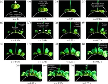
Flow images of vortex-ring collision with a
 $D/d=4$
round cylinder convex surface. Secondary vortex-ring cores move towards the collision axis before pairing up to produce a small-scale counter-rotating vortex dipole that moves in the opposite direction along the collision axis.

Figure 2 shows some of the key time-sequenced LIF flow images extracted from the video clip. Note that a thin fluorescent dye streak is shed by the primary vortex ring as it propagates towards the cylinder. However, it is not a vortex-ring trailing jet caused by the use of a stroke length greater than the critical value, and thus does not influence the intended collision process. Upon colliding with the cylinder, figure 2(b–d) show that the primary vortex-ring cores flatten and increase in ring diameter as they spread radially outwards, with an accompanying reduction in the vortex-core diameters. Thereafter, figure 2(d,e) show that the convex surface boundary layer separates under the influence of an adverse pressure gradient to produce the secondary vortex ring. Subsequently, the secondary vortex-ring cores turn and move towards the collision axis, as depicted in figure 2(f–h), though the primary vortex-ring cores remain relatively static but grow in significant size. This drastic growth in vortex-core diameter can be attributed to the circumferential flow along the primary vortex-ring filament from the collision point, which is driven by the curvature of the convex surface. Lim (Reference Lim1989) and Couch & Krueger (Reference Couch and Krueger2011) had already demonstrated this phenomenon earlier in their studies on vortex-ring collisions upon inclined walls, and the convex surface here can be treated as a wall with increasing inclination angle further away from the collision point. On the other hand, the secondary vortex-ring cores continue their journey towards the collision axis while more of the secondary vortex-ring filament crosses the laser sheet (see figure 2 h–k). At the same time, the primary vortex ring also induces a tertiary vortex ring to form, as seen from figure 2(g) onwards. However, it does not appear to play any significant role in the overall flow dynamics.
Eventually, both ends of the secondary vortex-ring cores meet along the collision axis. Interestingly, two additional small vortex pairs (i.e. vortex pairs A and B) with opposite rotational senses are formed between the secondary vortex-ring cores and the convex surface. However, their presence is short-lived, as they diffuse very rapidly after their formations. At this point, it appears that these vortex pairs are different visualized cross-sections of the secondary vortex ring as it closes in upon itself along the collision axis and undergoes significant vortical movements. This will be clarified further when the interpreted flow models are being discussed later. As the flow continues to develop, the secondary vortex-ring cores pair up to form a very small-scale mushroom-shaped vortex dipole which propagates towards the nozzle exit along the collision axis. Note that the primary vortex-ring cores transit to incoherence rapidly shortly after the secondary vortex-ring cores leapfrog over them and move towards the collision axis. On the other hand, these vortical motions do not appear to destabilize the secondary vortex-ring cores as they draw closer to each other towards the collision axis.
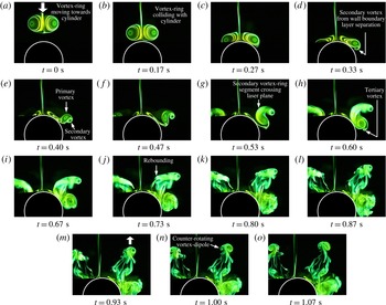
Flow images of vortex-ring collision with a
 $D/d=2$
round cylinder convex surface. Secondary vortex-ring cores pair up with segments of primary vortex ring to form a counter-rotating vortex dipole that moves away from the convex surface but parallel to the collision axis.

As the cylinder diameter ratio decreases to
 $D/d=2$
, as shown in supplemental video clip ‘Movie 2’ and figure 3, the initial flow behaviour of the vortex-ring collision is very similar to its
 $D/d=4$
counterpart seen earlier. For instance, gross structural deformations incurred by the primary vortex-ring cores, as well as subsequent formations of secondary and tertiary vortex-ring cores in the initial stages of the flow phenomenon, are in good general agreement, as can be readily observed from figure 3(a–f). However, it should be noted that flow differences begin to manifest shortly after the formation of the secondary vortex-ring cores here. In contrast to the
 $D/d=4$
cylinder, the present secondary vortex-ring cores as visualized along this plane do not move that much towards the collision axis as observed earlier, as shown in figure 3(f–i). Instead, increasingly larger segments of the secondary vortex-ring filament can be observed to cross the visualization plane closer to the collision axis during this period, before they appear to undergo an abrupt rebound away from the convex surface. Due to rapid dye dissipation, it is difficult to tell at this point whether rebounding is a result of the secondary vortex-ring segments colliding upon the convex surface or rapid and large vortical distortions to the secondary vortex-ring segments. This will be elaborated upon further in later discussions. Shortly after the above rebound phenomenon, the flow moves rapidly away from the convex surface and figure 3(j–l) show that the initially rather disorganized fluid flows close to the collision axis begin to reorganize themselves into a vortex core that pairs up with the secondary vortex-ring core to form a distinct counter-rotating vortex dipole on each symmetrical side of the convex surface. What is particularly interesting is that the vortex dipole moves away along a path that is parallel to the collision axis but offset by slightly more than half a cylinder diameter away, as indicated by the arrow and depicted sequentially in figure 3(m–o).
Finally, when the cylinder diameter ratio is reduced further to
 $D/d=1$
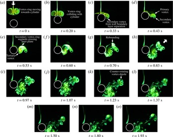
, the resulting flow phenomenon presented in supplemental video clip ‘Movie 3’ and figure 4 is perhaps the most intriguing. Once again, the general flow behaviour in the initial stages of the collision grossly resembles those discussed earlier, as shown in figure 4(a–f), except that the formation locations for secondary and tertiary vortex-ring cores are further delayed along the convex surface. And like the
 $D/d=2$
configuration, secondary vortex-ring segment crosses the visualization plane and causes flow ejections that produce a vortex core that moves away from the convex surface. This can also be seen in the accompanying video clip, where the basic phenomenon is very similar to the
 $D/d=2$
configuration and that rebounding of the secondary vortex segment off the convex surface is even more apparent. The ejected vortex core subsequently pairs up with the secondary vortex-ring core to form a counter-rotating vortex dipole that moves away from the convex surface at some angle away from the collision axis, as shown visually in figure 4(g–o). At the same time, the primary vortex-ring engulfs part of the secondary vortex ring within its proximity before it pairs up with the tertiary vortex ring to form another, but far more incoherent, vortex dipole near the cylinder lee side. However, this vortex dipole does not move away from the convex surface in the same manner as the previous counter-rotating vortex dipole. Instead, it convects very slowly away from the convex surface along a trajectory that is more or less a reflective symmetry (i.e. about the horizontal plane in the flow images) of the one traced out by the vortex dipole formed by the secondary vortex core and ejected fluids. At the same time, its coherence deteriorates rapidly due to viscous effects.
Flow images of vortex-ring collision with a
 $D/d=1$
round cylinder convex surface. Secondary vortex-ring cores pair up with segments of primary vortex ring to form a counter-rotating vortex dipole that moves at some angle away from the convex surface.

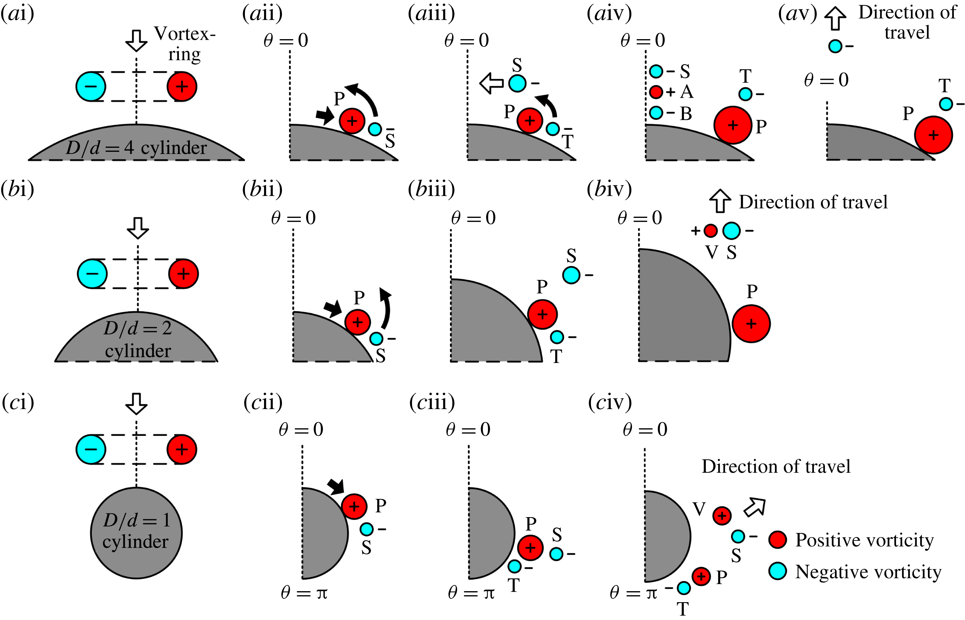
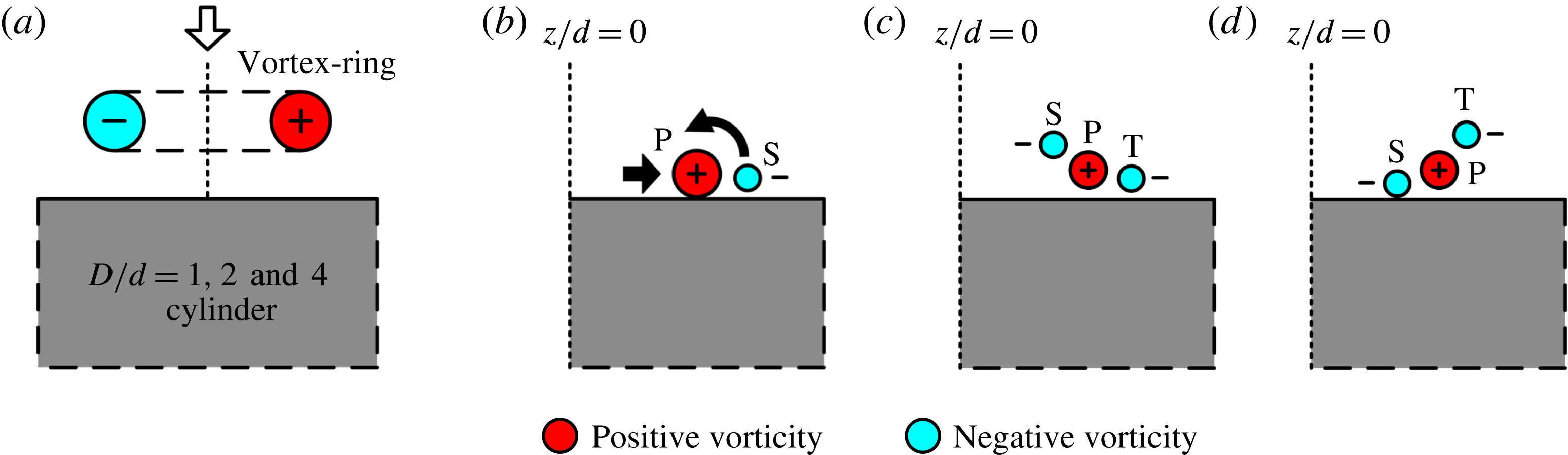
To summarize the resulting vortical structures and behaviour inferred from the flow visualizations so far, figure 5 illustrates the various vortex-ring cores and their vortical changes schematically. As earlier flow visualizations have demonstrated high levels of flow symmetry, the schematics will be presented for only half the cylinders for the sake of simplicity. Note also that the flow sequence depicted for each collision test case is not presented on the basis of a fixed time-interval, but rather in a way such that the most important vortical changes are highlighted. With reference to the figure, red and blue colours indicate positive and negative vorticities (i.e. counter-clockwise and clockwise rotational senses), respectively. The primary vortex-ring cores which collide with the convex surface are denoted as ‘P’, while the induced secondary and tertiary vortex-ring cores are denoted as ‘S’ and ‘T’, respectively. For the
 $D/d=4$
round cylinder test case, ‘A’ and ‘B’ are used to annotate the small vortex pairs A and B. Lastly, ‘V’ is used to indicate the reorganized and ejected vortex core produced by the secondary vortex-ring segment colliding with the convex surface. Note that the sizes of the vortices are based on observations from the flow visualizations; hence they are qualitative and not directly correlated to their actual strengths.
A summary of the vortex-ring structures and behaviour along the convex surfaces associated with vortex-ring collisions upon (a)
 $D/d=4$
, (b)
 $D/d=2$
and (c)
 $D/d=1$
round cylinders.
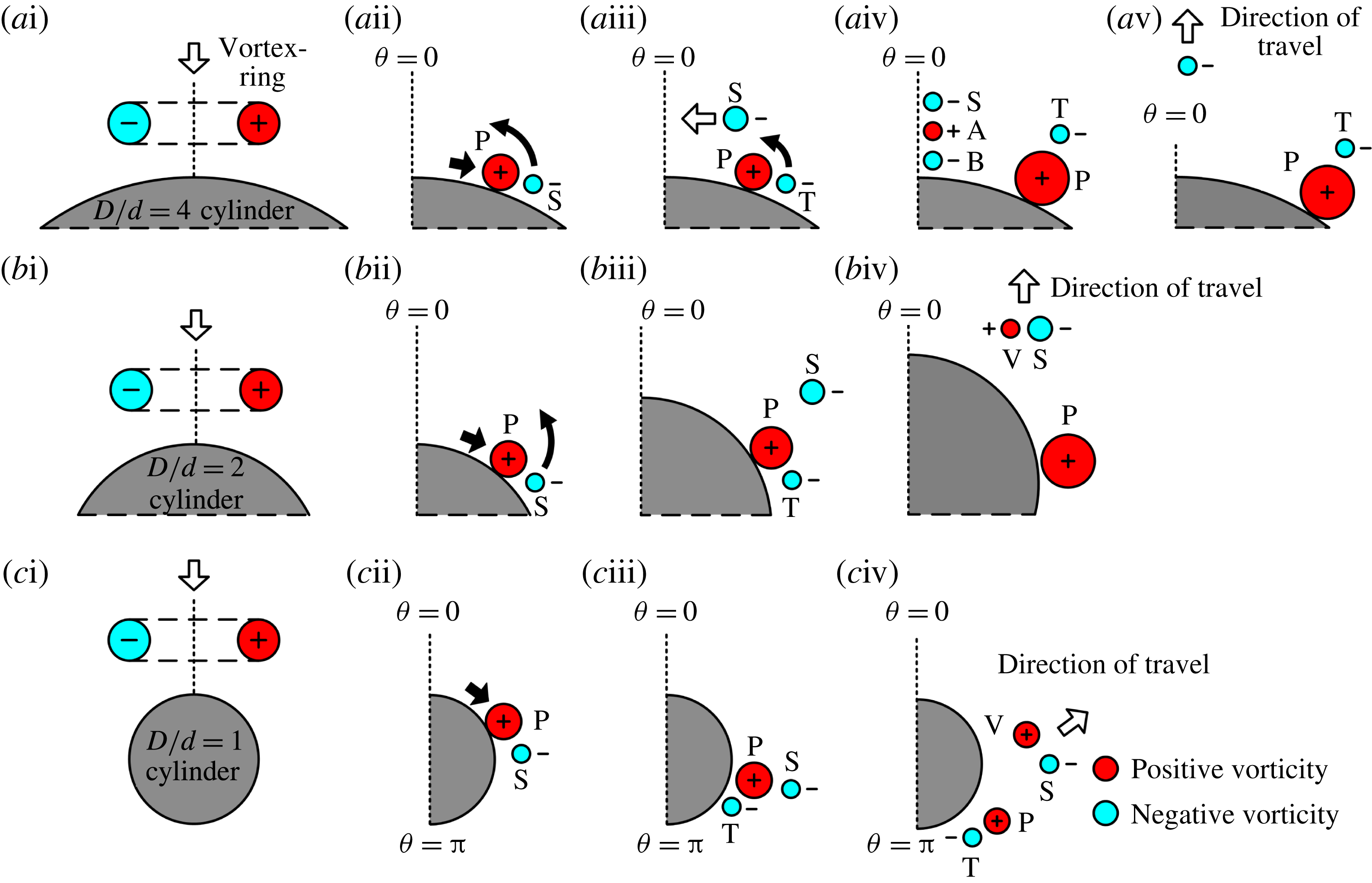
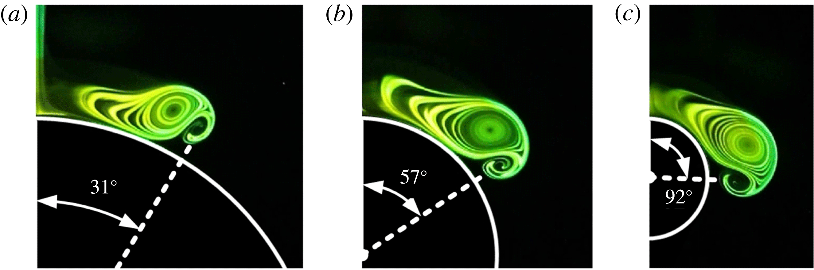
Correlating the preceding results, it would appear that secondary vortex-ring formation plays a significant role in the formation of vortex dipoles and their trajectories. Since the vortex dipoles are only produced when the primary and secondary vortex rings begin to interact significantly, the exact location at which the secondary vortex-ring core forms along the convex surface is expected to affect the resulting vortex-dipole trajectory directly. To illustrate that, figure 6 shows a comparison of the convex surface locations at which secondary vortex-ring cores are observed to form discernibly. While they are qualitative in nature, it can nevertheless be observed that formation of the secondary vortex-ring core initiates at approximately
 $31^{\circ }$
,
 $57^{\circ }$
and
 $92^{\circ }$
along the convex surfaces of the
 $D/d=4$
, 2 and 1 cylinders, respectively. As such, it can be inferred that the secondary vortex-ring core begins to interact with the primary vortex-ring core progressively further away along the convex surface as the diameter ratio decreases. This subsequently leads to increasingly further formation of the vortex dipole along the convex surface and, hence, an increase in the angle at which it eventually moves away from it. In fact, this behaviour underpins the flow mechanism that the authors postulate later to account for the flow observations associated with different diameter ratios here.
Secondary vortex-ring initiation locations along the convex surfaces of (a)
 $D/d=4$
, (b)
 $D/d=2$
and (c)
 $D/d=1$
round cylinders.

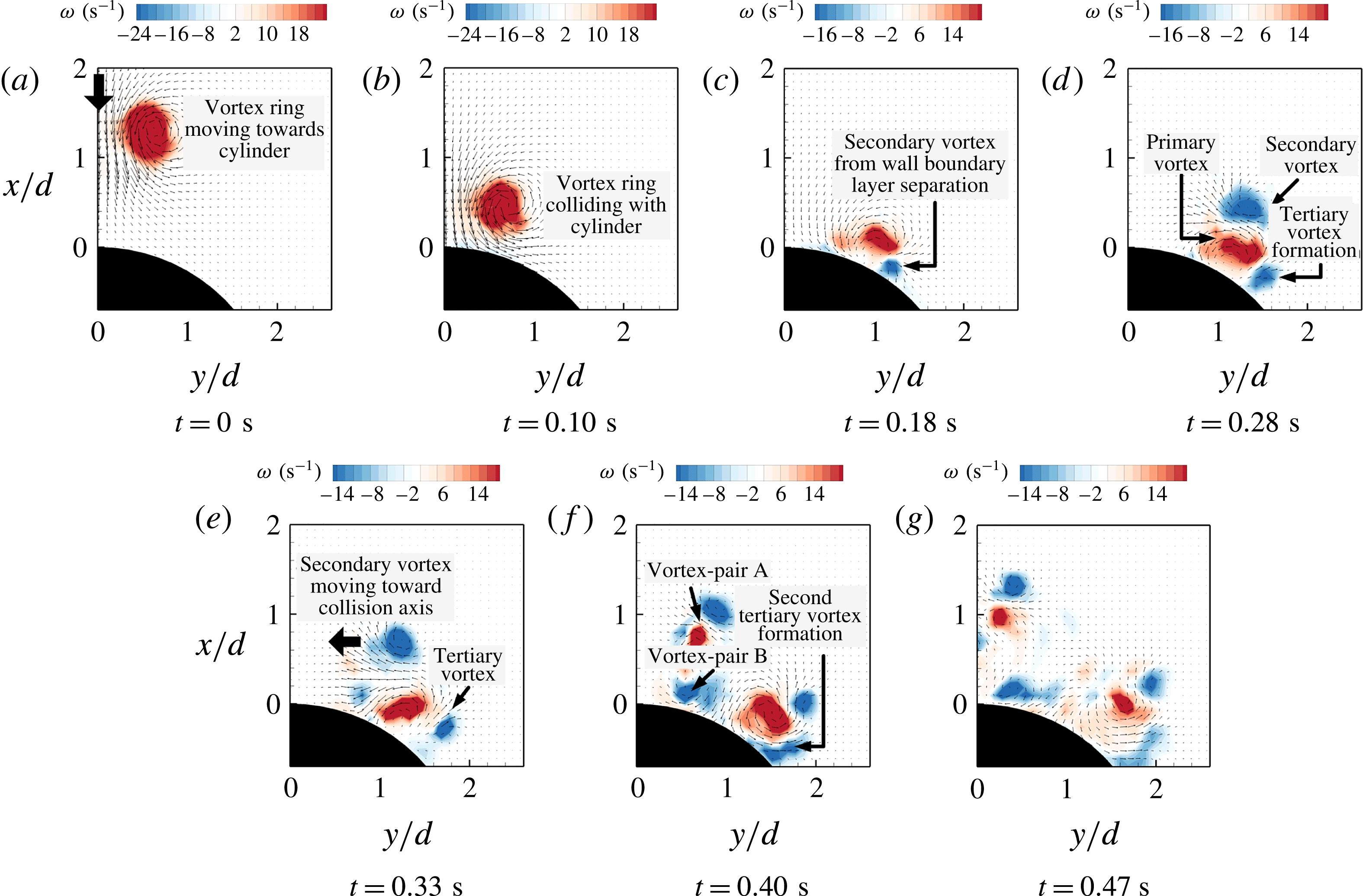
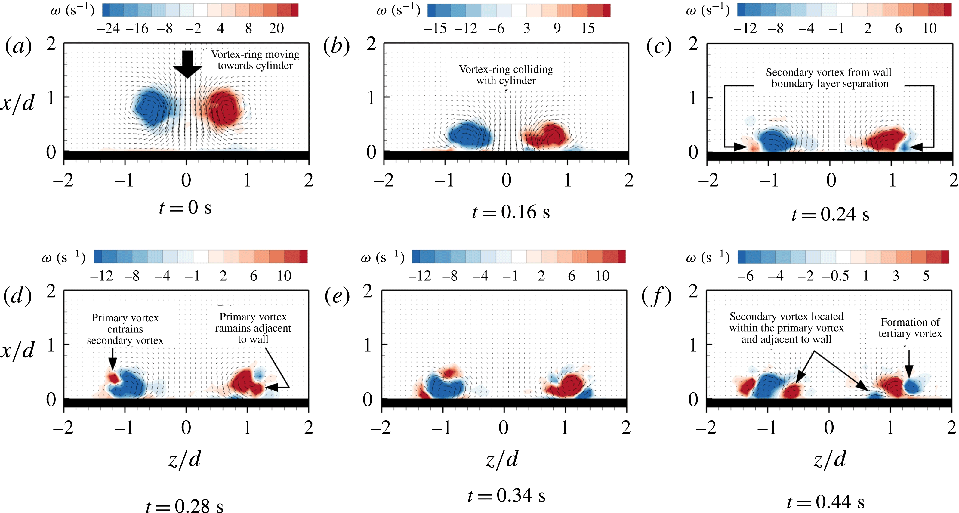
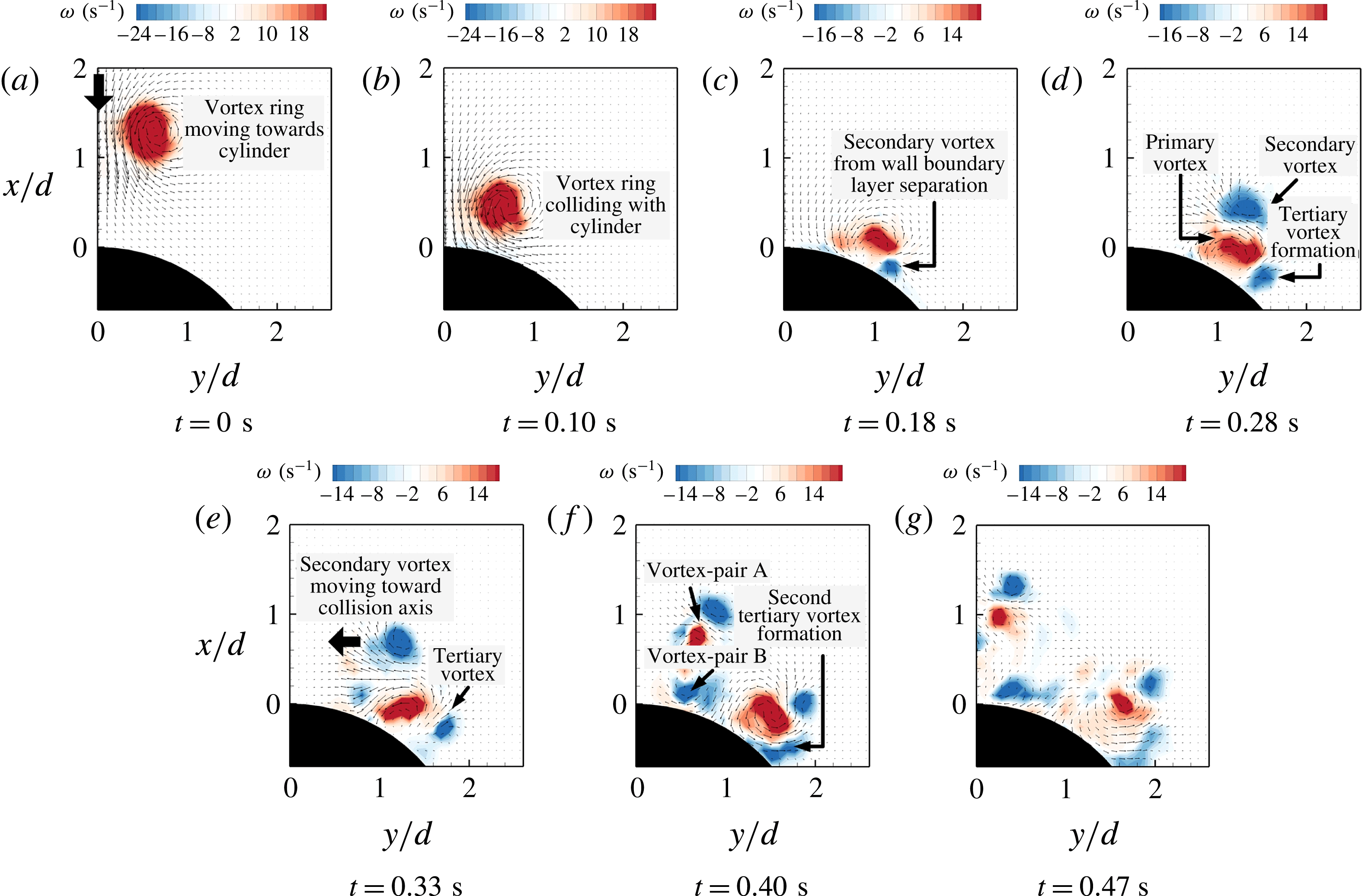
Time-sequenced velocity and vorticity maps associated with vortex-ring collision with a
 $D/d=4$
round cylinder convex surface.
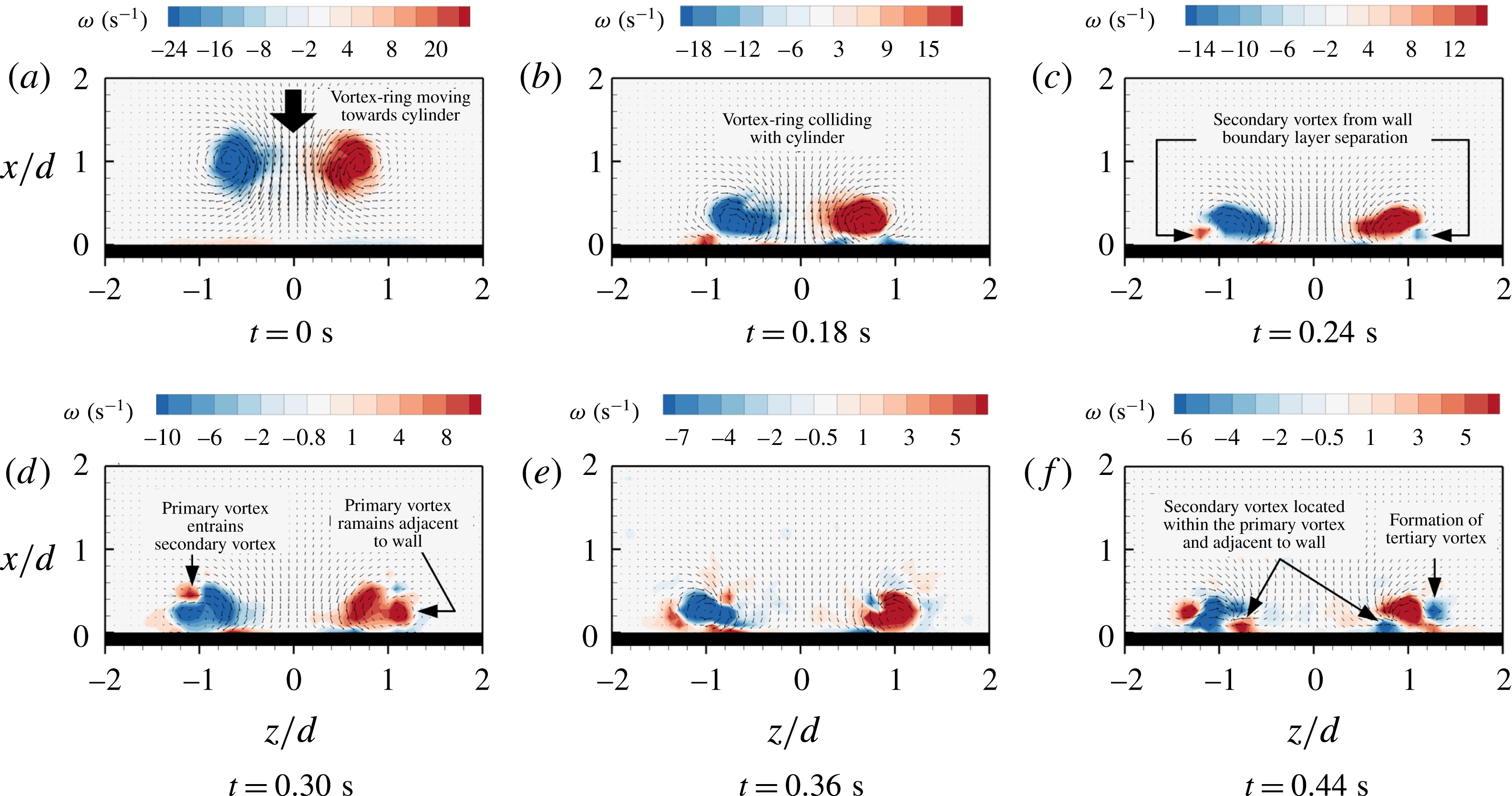
Time-sequenced velocity and vorticity maps associated with vortex-ring collision with a
 $D/d=2$
round cylinder convex surface.
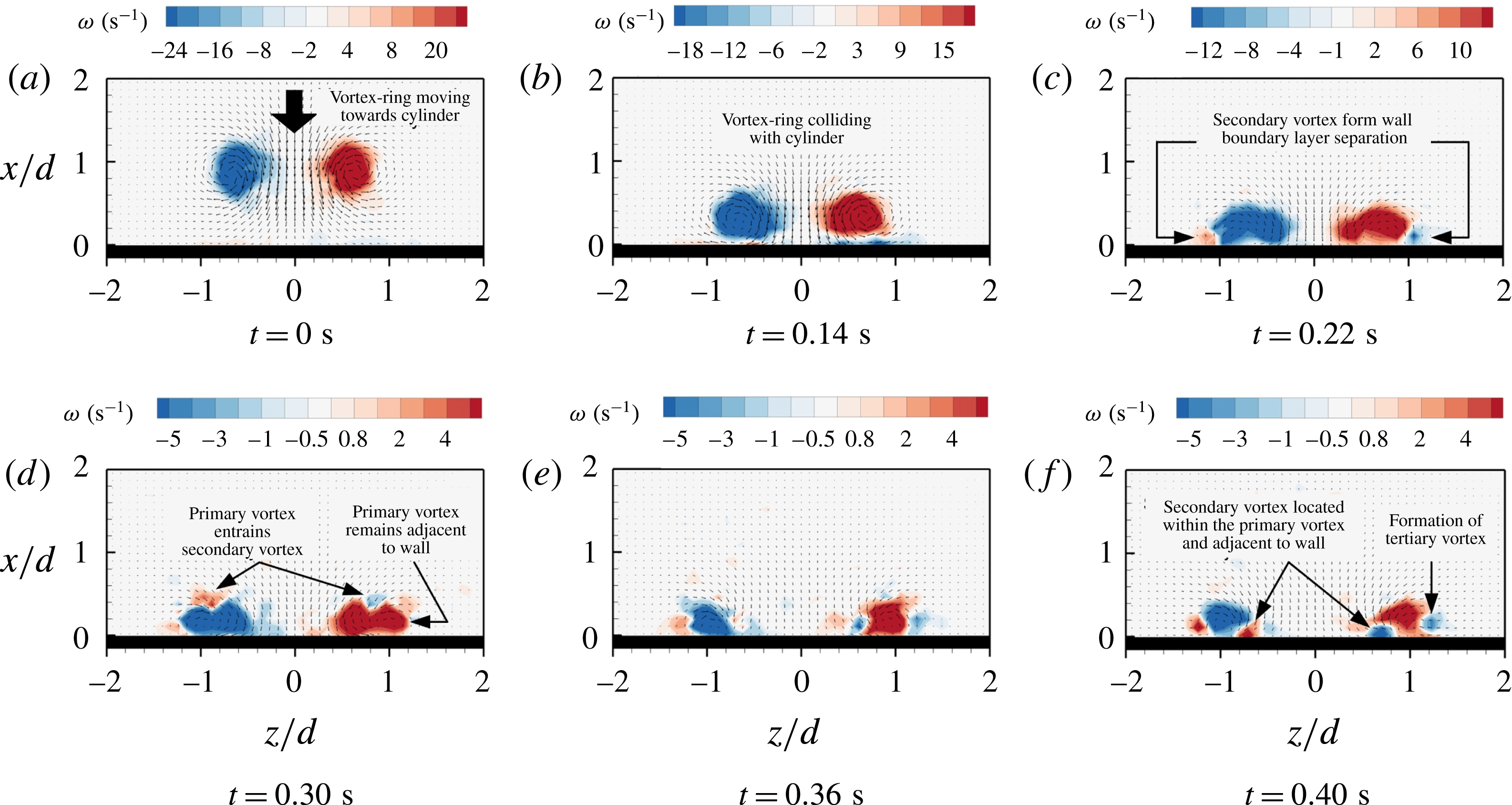
Time-sequenced velocity and vorticity maps associated with vortex-ring collision with a
 $D/d=1$
round cylinder convex surface.

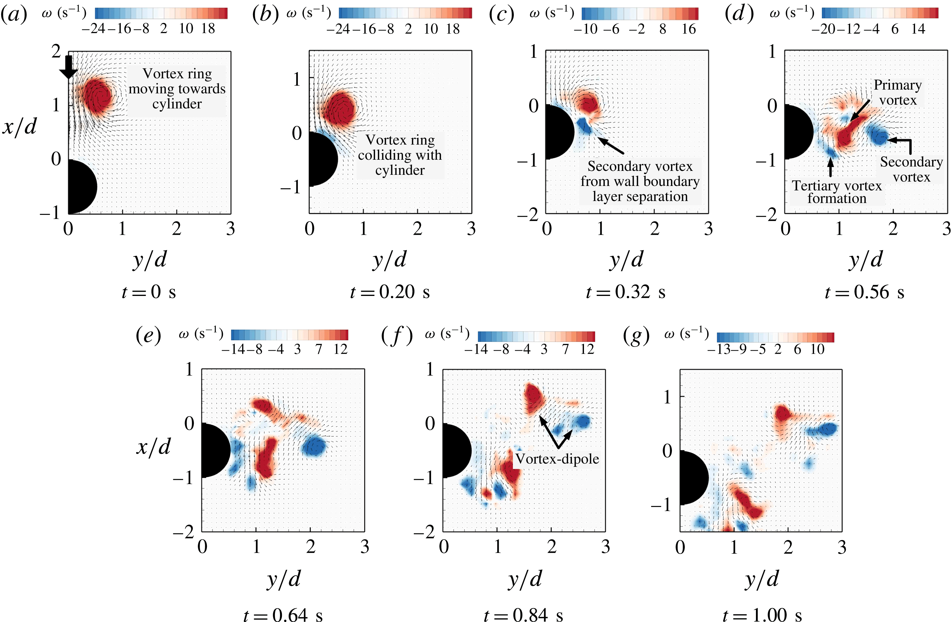
To complement the flow visualizations presented earlier and shed more light on the flow developments, instantaneous velocity and vorticity fields derived from TR-PIV measurements are presented in figures 7–9. Note that only half of symmetrical flow fields are presented for each test cylinder, and the vorticity distributions are presented to highlight the key vortex structures and their flow changes. It can be seen that they are in excellent agreement with the flow visualizations shown earlier, indicating that any scalar diffusion of the fluorescent dye during the flow visualization experiments remains minimal and the LIF results depict the flow fields accurately. For instance, figure 7 shows the scenario whereby the secondary vortex-ring core is being entrained by the primary vortex-ring core and moving towards the collision axis, not to mention the successful detection of two instances of tertiary vortex-ring cores. Furthermore, the existence of small-scale vortex pairs A and B observed in the earlier flow visualizations are also confirmed in figure 7(f).
Correspondingly, figure 8 clearly shows the ejection of a vortex core away from the convex surface, which subsequently pairs up with the secondary vortex-ring core to produce a vortex dipole that moves away from the convex surface in a trajectory that is parallel to the collision axis. Last but not least, figure 9 shows that the resulting vortex dipole will move away from the convex surface at some angle with respect to the collision axis, where this angle is visually close to the one observed in the earlier visualization results. For the sake of completeness in presenting all relevant experimental results here, corresponding results taken for the vortex-ring collisions but along the straight edges will now be presented and discussed.
3.2 Collision behaviour along the straight edges
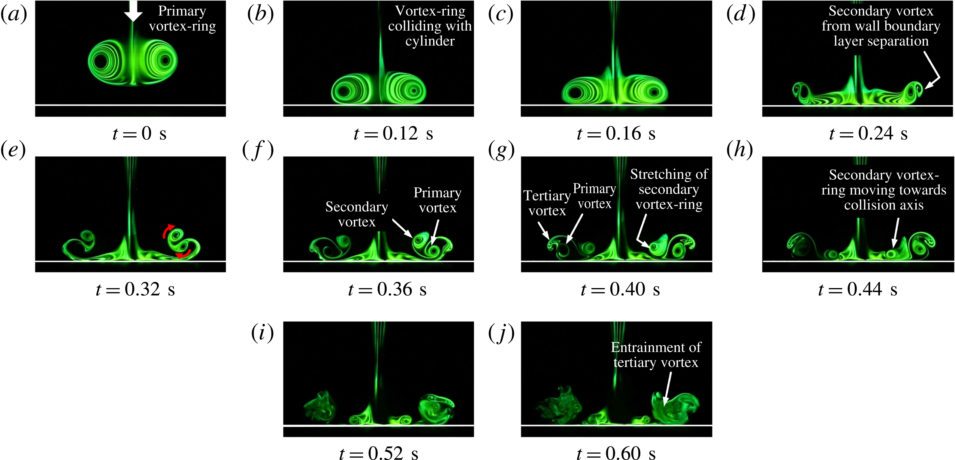
Figure 10 shows LIF results for head-on vortex-ring collision upon a
 $D/d=4$
round cylinder, but along the cylinder straight edge instead. Similar to observations made for vortex-ring collisions upon flat surfaces, the primary vortex-ring diameter increases radially and gradually flattens as it collides with the straight edge in the initial stages, as shown in figure 10(a–c). What sets the present flow scenario apart from head-on vortex-ring collision with a flat surface, however, is the slightly faster reduction in the primary vortex-ring core size shortly after the vortex ring encounters the round cylinder, as depicted in figure 10(d). Note that this was observed in figure 2(a–e) earlier on, and hence associated with the stretching of the vortex-ring filament as parts of the primary vortex-ring wrap themselves around the round cylinder as they convect along the convex surface (New & Long Reference New and Long2015). It should be mentioned that the formation of secondary vortex-ring cores can also be observed in figure 10(d), where they continued to be entrained within the confines of the primary vortex-ring cores, as shown in figure 10(e–h). Note also that the primary vortex-ring cores are sheared along the straight edge from figure 10(d) onwards as the diameter of the primary vortex ring increases during the collision process, due to the ‘no-slip’ condition. At the same time, formation of tertiary vortex-ring cores can be seen to initiate and develop from figure 10(f) onwards as well, the behaviour of which closely resembles that of the secondary vortex-ring cores, except that it does not get entrained by the primary vortex ring completely.
Flow images of vortex-ring collision with a
 $D/d=4$
round cylinder straight edge. Gross flow behaviour is similar to that associated with head-on vortex-ring collision upon flat surfaces, where secondary and tertiary vortex rings are being entrained by the primary vortex ring.

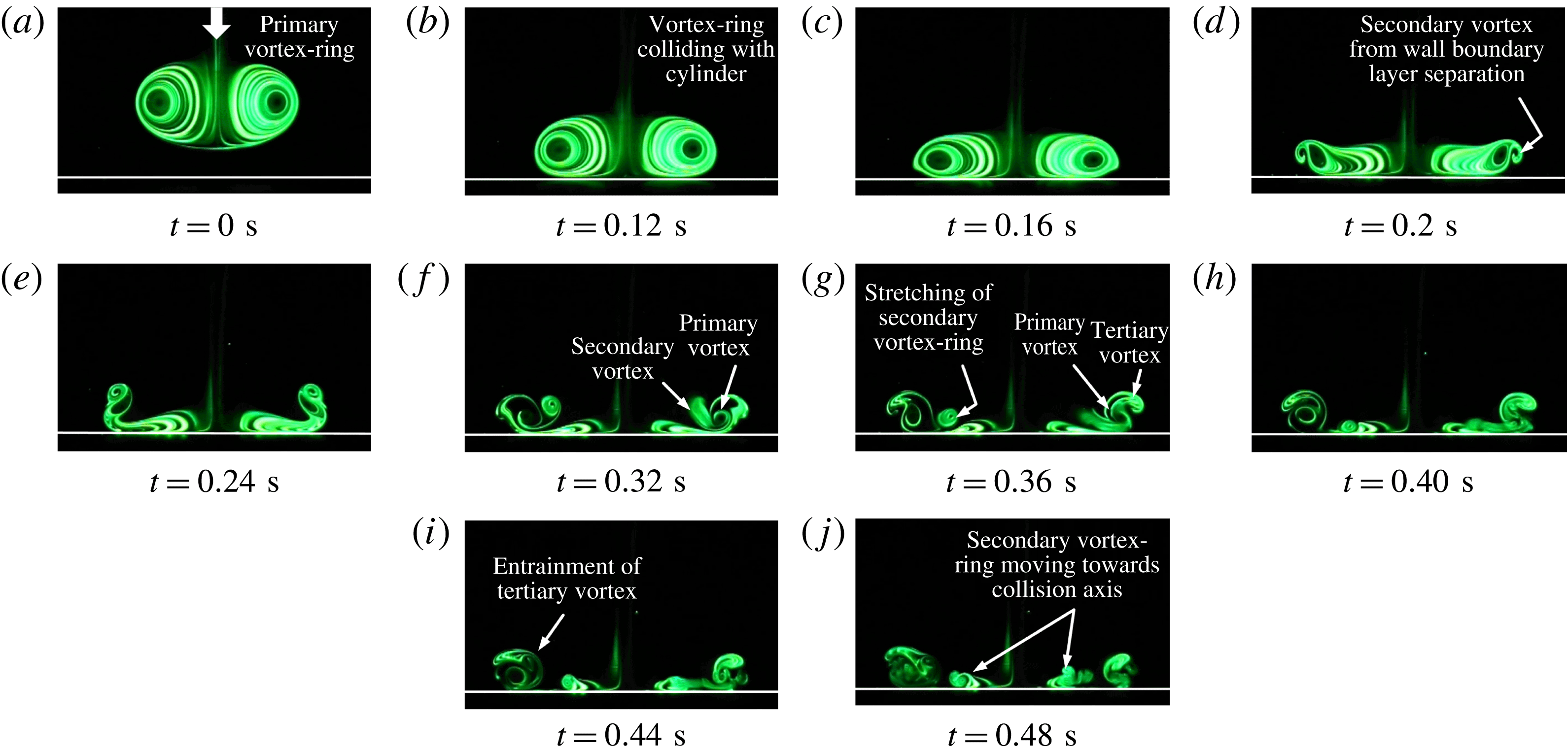
Flow images of vortex-ring collision with a
 $D/d=2$
round cylinder straight edge. General flow behaviour remains similar to the case associated with the
 $D/d=4$
round cylinder.

Returning to the secondary vortex-ring cores, once they get entrained by the primary vortex-ring cores, they approach and interact with the primary vortex-ring core vorticity that was sheared along the straight edge, before they settle down in a relatively coherent manner adjacent to the straight edge. However, these interactions render the primary vortex-ring cores more incoherent and the secondary vortex-ring cores are observed to reduce in size as they move slightly towards the collision axis as well, though they never meet during the entire flow visualization experiment. The core size reduction and movement towards the collision axis are postulated to be related to vortex-stretching effects upon the secondary vortex-ring filament, similar to what was discussed for the primary vortex ring earlier on. It should be clear to readers who are familiar with vortex-ring collisions that the entire flow sequence presented in figure 10 is discernibly more unstable than that associated with head-on vortex-ring collisions with flat surfaces. Note that several similar experiments were conducted before the best possible results are included in figure 10. However, it should not come as a surprise if one considers the significantly non-uniform vortex-stretching effects conferred upon the primary, secondary and possibly tertiary vortex-ring cores here, not to mention their mutual interactions under those effects. This can be discerned rather easily from figure 10(i,j), where there exist rapid transitions to incoherence and dye diffusion.
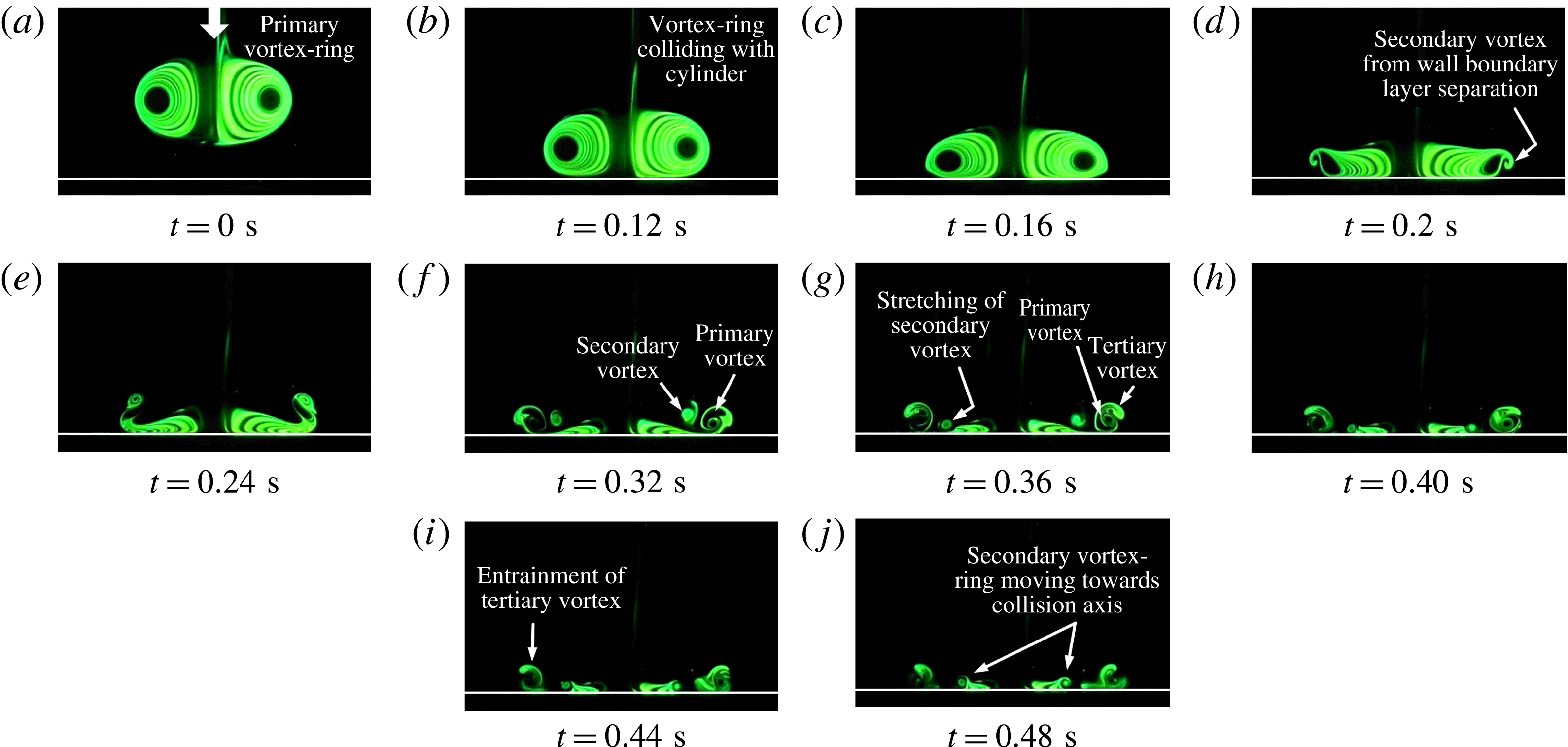
Flow images of vortex-ring collision with a
 $D/d=1$
round cylinder straight edge. Note the more rapid reduction in primary and secondary vortex-ring core sizes when the diameter ratio reduces to
 $D/d=1$
.

A summary of the vortex-ring structures and behaviour along the straight edges associated with vortex-ring collisions upon
 $D/d=1$
, 2 and 4 round cylinders.

When the diameter ratio is reduced to
 $D/d=2$
and 1, as shown in figures 11 and 12 respectively for the sake of completeness, relatively similar behaviour continues to manifest from the collision process. This does not come as a surprise, however, since the straight edges do not undergo geometrical changes as drastic as those associated with the convex surfaces when the diameter ratio is varied. Hence, their behaviour will not be described in detail again, except for one or two more notable exceptions that can be discerned from the figures. For the sake of completeness, a summary of the vortex structures and behaviour based on the observations made in figures 10–12 is also shown in figure 13. Returning to the more notable flow exceptions, even though the results presented in figures 10–12 are visualization-based and are less coherent than those taken along the convex surfaces, it can nonetheless be discerned that reductions in the diameter ratio lead to increasingly more rapid reductions in the primary and secondary vortex-ring core sizes. Such an observation agrees well with the notion of increasingly higher vortex-stretching effects conferred upon the various vortex-ring structures due to decreasing diameter ratios. Lastly, as with the preceding case along the convex surface, velocity and vorticity fields associated with vortex-ring collisions with the three round cylinder straight edges are determined from TR-PIV measurements and shown in figures 14–16 to complement the overall flow visualization results.
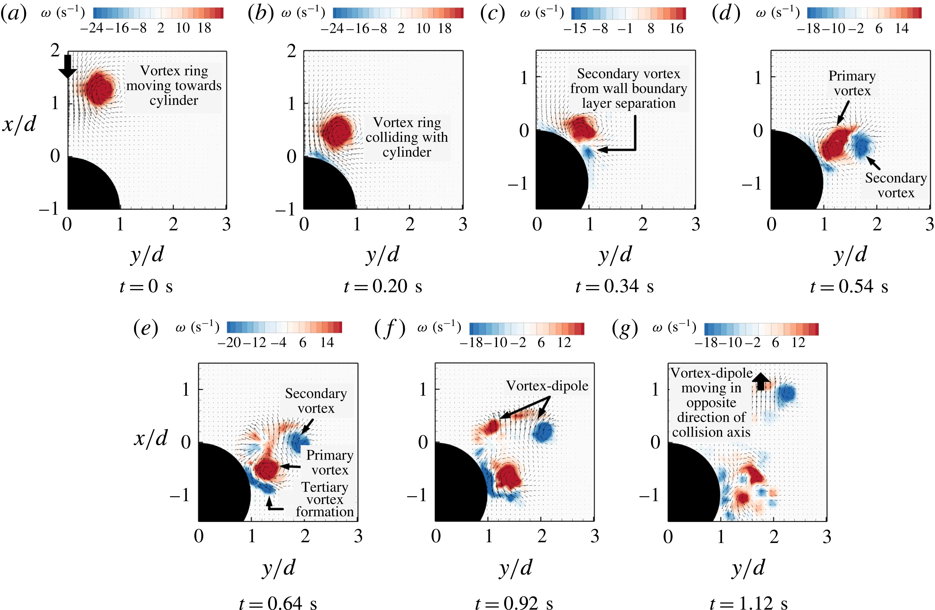
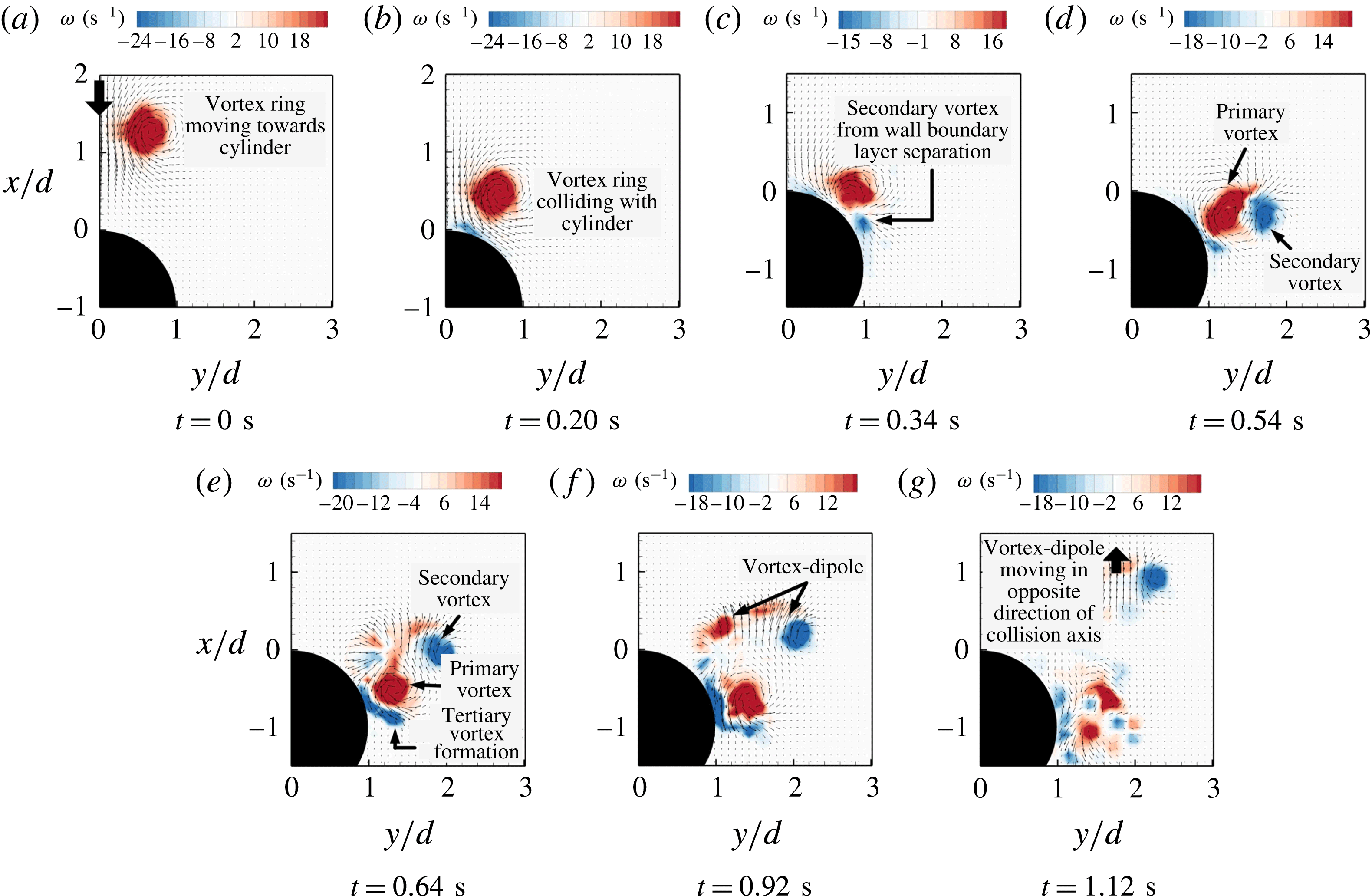
Time-sequenced velocity and vorticity maps associated with vortex-ring collision with a
 $D/d=4$
round cylinder straight edge.

Time-sequenced velocity and vorticity maps associated with vortex-ring collision with a
 $D/d=2$
round cylinder straight edge.

Time-sequenced velocity and vorticity maps associated with vortex-ring collision with a
 $D/d=1$
round cylinder straight edge.

Once again, good agreement between the LIF visualizations and TR-PIV results presented in figures 14–16 can be observed. The velocity vectors and vorticity distributions clearly demonstrate that the behaviour of the vortex rings after they collide with the round cylinders is practically insensitive to the cylinder diameter. Just like the LIF visualizations showed previously, the collided primary vortex rings lead to the formation of secondary vortex rings after the collisions. The secondary vortex rings are subsequently entrained by the primary vortex rings into the confines of the latter, while tertiary vortex rings begin to be induced by the primary vortex rings. The results also show that the primary vortex rings do not appear to rebound off the cylinder straight edges, despite strong similarities between the 2D behaviour seen in figures 14–16 and that associated with vortex-ring collisions with flat surfaces. In this case, the lack of any distinct rebounding is most likely caused by the significant vortex-stretching effects associated with the primary vortex ring continuing to convect along the convex surface after the point of collision. This clearly does not happen for vortex-ring collisions with flat surfaces, and will explain why flat surfaces rather than convex surfaces will promote rebounding of the primary vortex ring. Lastly, the secondary vortex ring become more apparent as the diameter ratio reduces in these TR-PIV measurement results and supports the notion that vortex stretching of the various vortex rings around the round cylinders becomes more significant with smaller diameter ratios.
3.3 Vortex-core trajectories
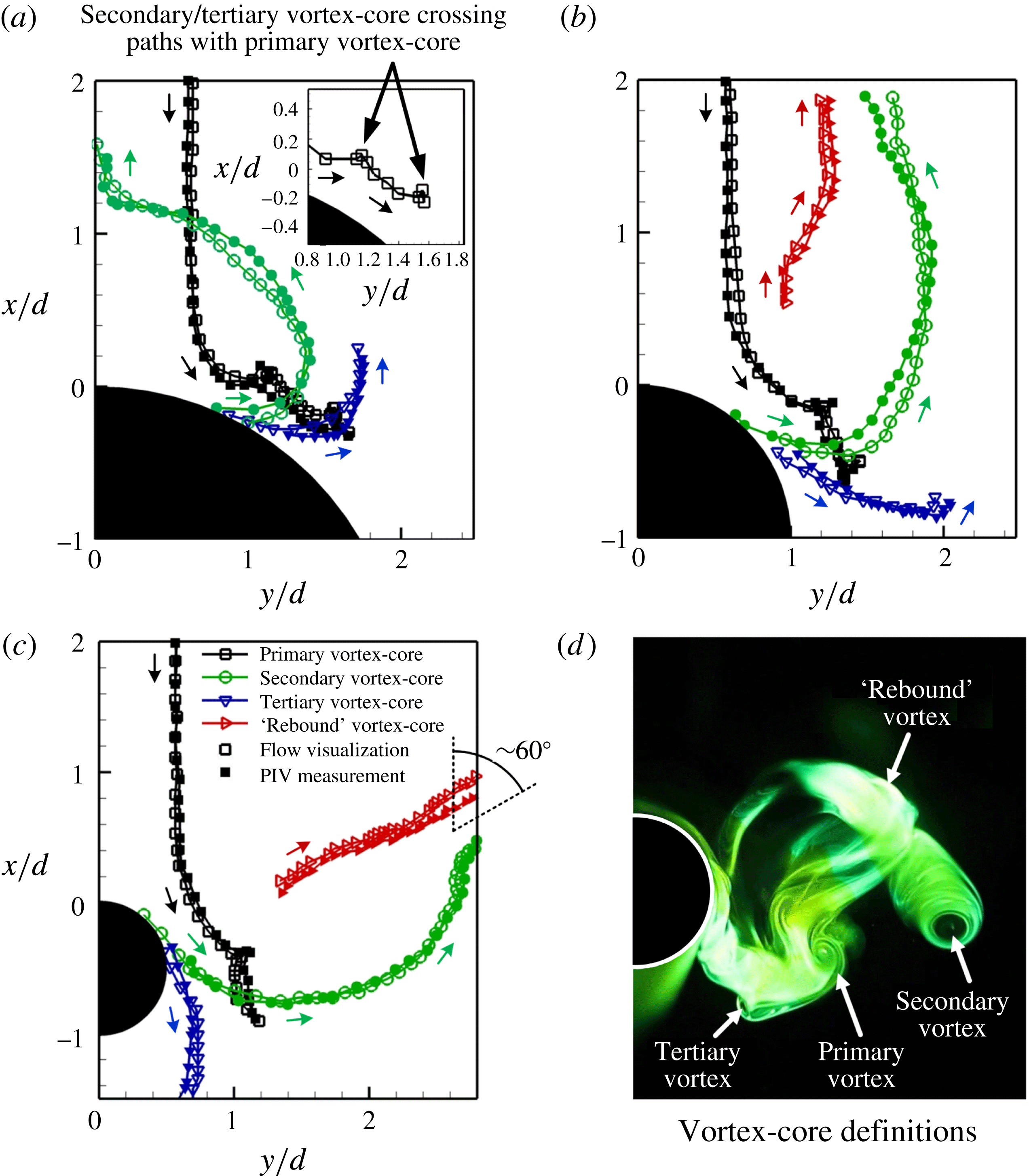
Vortex-core trajectory results are presented in figure 17, where trajectories for the primary, secondary, tertiary and ‘rebound’ vortex cores are depicted for vortex-ring collisions upon the convex surfaces. Corresponding trajectories for vortex-ring collisions upon the cylinder straight edges were not presented, as figures 10–15 have shown that the primary, secondary and tertiary vortex-core trajectories do not deviate too much from that associated with vortex-ring collision upon a flat surface. Furthermore, there is no rebounding of vortices occurring along the cylinder straight edges. To address any potential issues surrounding the repeatability of the present experiments, figure 17 allows comparisons between the trajectories of all discernible vortex cores determined from both LIF visualizations and TR-PIV vorticity results (i.e. empty and filled symbols, respectively). In this case, vortex-core locations of the various vortex structures are first determined from the LIF visualization results by adopting similar procedures as those used by New et al. (Reference New, Shi and Zang2016) in tracking vortex-core trajectories associated with collisions of vortex rings on inclined surfaces. This was done by visually inspecting the various vortex structures to determine the vortex-core locations at every 1/30 s interval. During the course of that study, it has been observed that good agreement in the vortex-core trajectories exists between those determined from qualitative LIF visualization images, as well as quantitative instantaneous vorticity maps and
 $\unicode[STIX]{x1D706}_{2}$
-criterion (studies such as Saffman (Reference Saffman1970) and Weigand & Gharib (Reference Weigand and Gharib1997) have determined their vortex-core trajectories from vorticity field results). Note also that, due to the rapid diffusion of the fluorescent dye after the collisions, vortex-core locations were only extracted up to the point where they remained visually distinguishable.
Vortex-core trajectories associated with vortex-ring collision with (a)
 $D/d=4$
, (b)
 $D/d=2$
and (c)
 $D/d=1$
round cylinders, as extracted from LIF visualizations and TR-PIV measurements. Definitions for the various vortex cores are shown in (d).
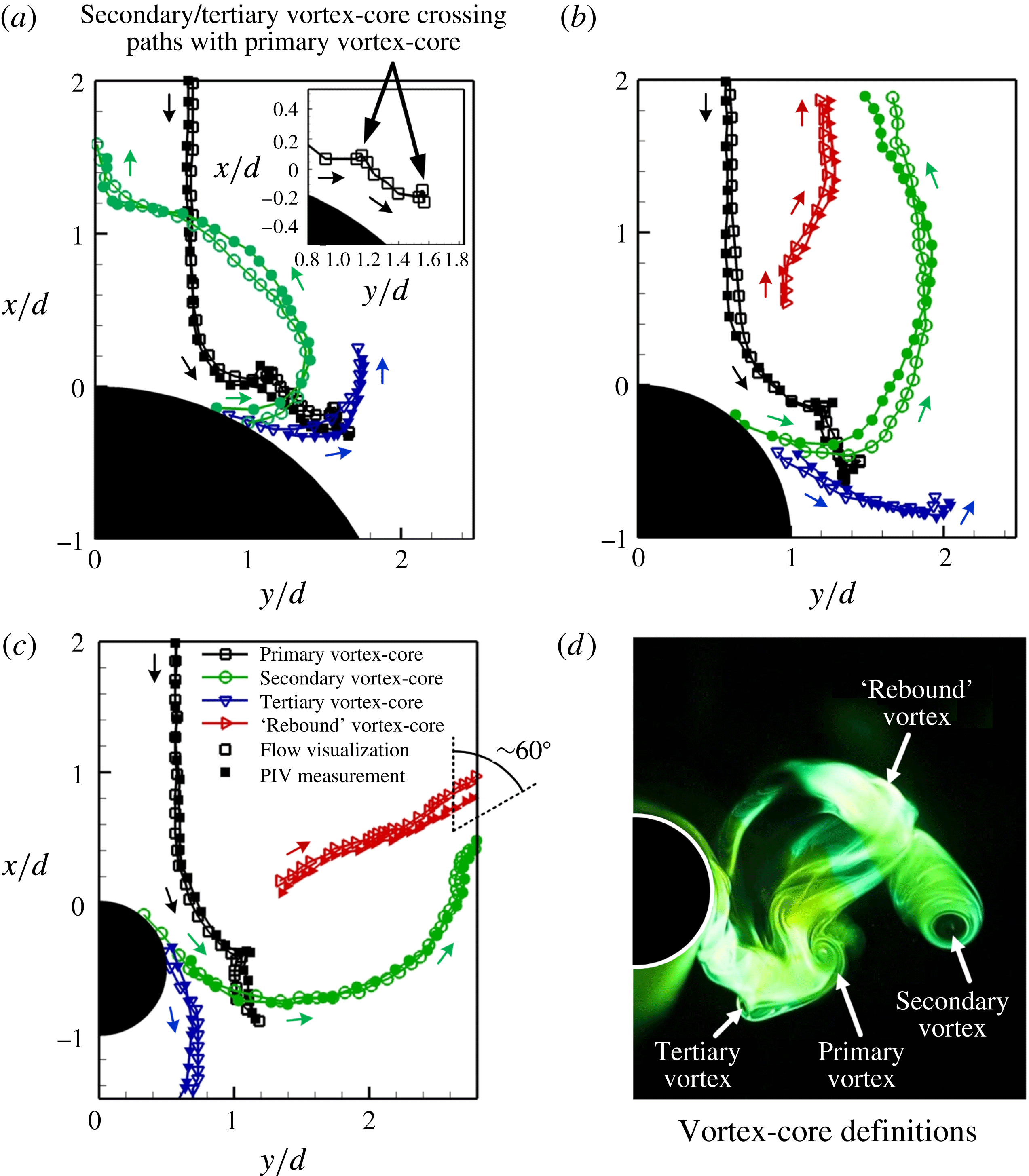
As for the TR-PIV vorticity results, vortex-core locations of the different vortex structures were determined by tracking clear concentrated vorticity regions that are associated with the vortex cores at every 1/40 s interval. Note that the LIF visualizations and TR-PIV vorticity results for the same test cylinder were conducted across different experiments. Hence, comparisons between the vortex-core locations between the two different experimental techniques for all test cylinders will demonstrate how repeatable the experiments had been. It can be discerned from figure 17 that there exists reasonably good repeatability between different experiments on the same test cylinder. The vortex-core trajectories from both the LIF and TR-PIV vorticity results are in satisfactory agreement despite the inevitable background flow differences across different experiments, especially when one relied on a scalar dye and another on particle imaging.
More discernible discrepancies only manifest during certain stages of the trajectories associated with the secondary vortex cores after they are formed and convect upstream towards the nozzle for
 $D/d=2$
and 4 test cylinders. A similar, more significant discrepancy can also be observed in the early stages of the trajectories associated with the tertiary vortex cores after they are formed but before they convect upstream towards the nozzle for the
 $D/d=4$
test cylinder, as well as the later stages of the vortex-dipole trajectories. Other than these, vortex-core trajectories from both experimental approaches match up quite well and demonstrate that key vortex structures such as the primary, secondary and tertiary vortices are universal to vortex-ring collisions upon all test cylinders here. On the other hand, they also confirm that the rebound vortices only manifest in
 $D/d=2$
and 1 test cylinders.
In figure 17(a) where vortex-core trajectories associated with the
 $D/d=4$
cylinder are presented, one can clearly discern the significant trajectory traced out by the secondary vortex core, from the point it is formed along the cylindrical convex surface to when it moves upstream towards the collision axis and meets its counterpart produced along the other half of the cylinder. The primary vortex-core trajectory is also clearly disrupted by the formation and close proximity of the secondary and tertiary vortex cores, as can be seen by the two ‘kinks’ in the later stages of the primary vortex-core trajectory (see inset in figure 17
a). It is worth mentioning that these disruptions could not easily be detected by playing back the LIF visualization videos, and quantifications of the vortex-core trajectories remain the most effective approach. As for the tertiary vortex core, its trajectory resembles that of the secondary vortex core in terms of curving upstream, but it diffuses rapidly through viscous effects before it is able to turn towards the collision axis.
As for the vortex-core trajectory associated with
 $D/d=2$
cylinder shown in figure 17(b), the primary vortex-core trajectory is in general agreement with that seen in figure 17(a) but delayed further along the cylindrical convex surface. Similarly, two ‘kinks’ in its trajectory signify the effects conferred by the formation and close presence of the secondary and tertiary vortices. On the other hand, secondary and rebound vortex-core trajectories depicted here confirm what was observed in the LIF visualizations earlier on, where they both move upstream separately before coalescing together and convecting in the opposite direction to the collision axis as a vortex dipole. The tertiary vortex core moves towards the downstream direction after it is formed and, although it begins to move in the upstream direction, the attempt is short-lived due to its rapid diffusion. Lastly, for the
 $D/d=1$
cylinder shown in figure 17(c), both the secondary and rebound vortex cores move away from the cylindrical surface separately, before moving towards each other and coalescing together as a vortex dipole eventually, albeit at an angle relative to the collision axis. This is similar to the flow scenario for the
 $D/d=2$
cylinder, except that the coalesced vortex dipole travels at an estimated angle of approximately
 $60^{\circ }$
away from the collision axis. On the other hand, the tertiary vortex core moves in the downstream direction relatively parallel to the collision axis shortly after it is formed.
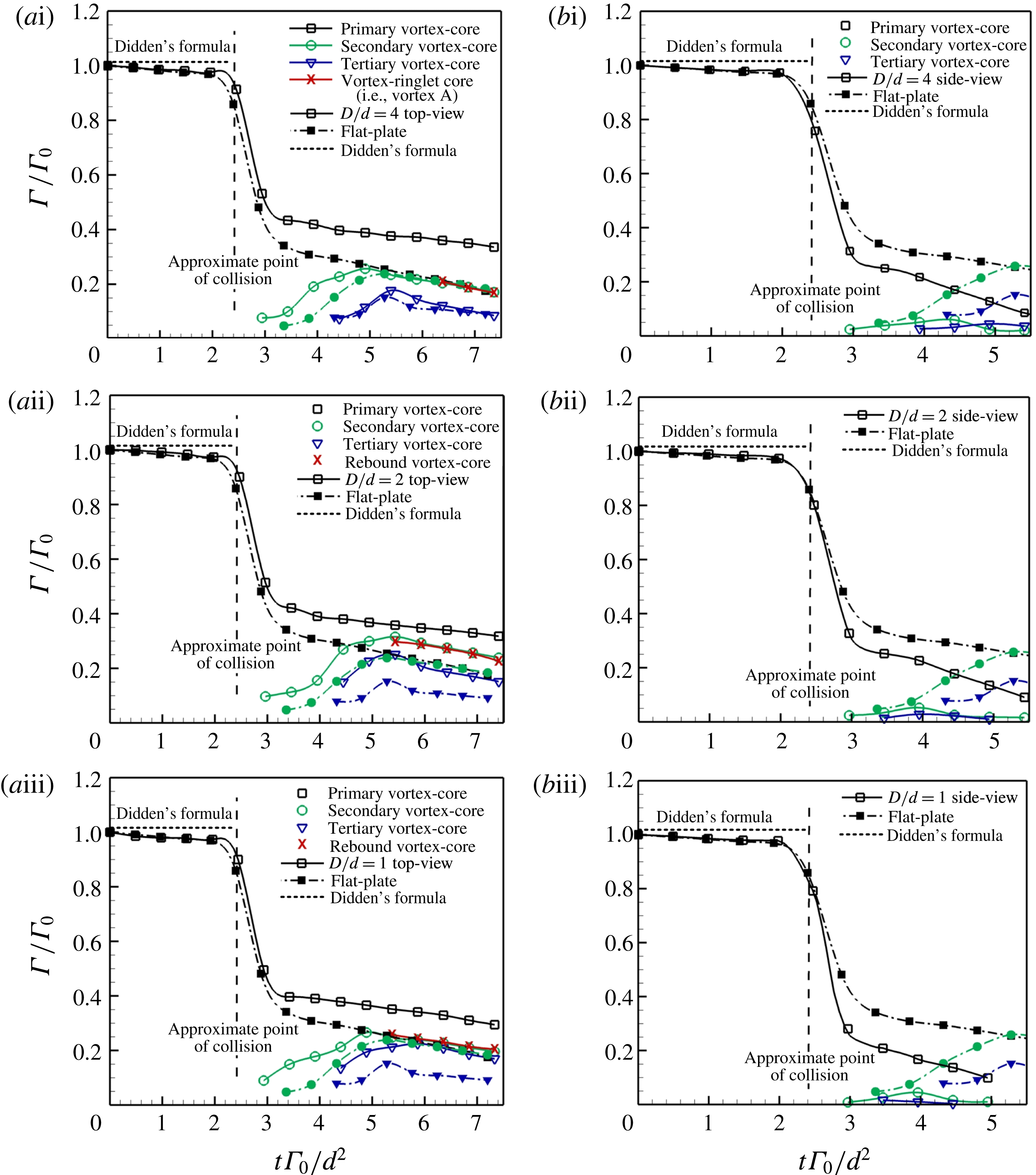
Temporal evolution of the vortex-ring core circulations along (a) convex surfaces and (b) straight edges for (i)
 $D/d=4$
, (ii)
 $D/d=2$
and (iii)
 $D/d=1$
round cylinders. Note that
 $\unicode[STIX]{x1D6E4}_{0}$
was taken at 2
 $d$
away from the cylinder surface.

3.4 Vortex-core circulations
To provide more quantitative comparisons, as well as shed additional light on the vortex-ring collision phenomenon here, figure 18 shows the vortex-core circulations estimated for the key vortex structures captured in the TR-PIV measurements. Note that the circulations were estimated for both along the convex surfaces and straight edges (i.e. indicated by empty symbols). While these estimates were based on 2D TR-PIV measurements, they will nonetheless allow some first-hand information on the effects of cylinder curvature and flow differences between the convex surfaces and straight edges. To arrive at a vortex-core circulation estimate, the vorticity field was integrated over the vortex-core area by invoking Stokes theorem:
 $$\begin{eqnarray}\unicode[STIX]{x1D6E4}=\oint _{c}\boldsymbol{V}\boldsymbol{\cdot }\text{d}\boldsymbol{l}=\iint _{s}\boldsymbol{w}\boldsymbol{\cdot }\text{d}\boldsymbol{S}.\end{eqnarray}$$
Since the test cylinders were located such that their surfaces were always at a distance
 $6d$
away from the nozzle exit, the vortex-core circulations were only estimated from the point where the vortex rings were located
 $2d$
away from the test cylinder surfaces. Note that the circulations were non-dimensionalized by the initial vortex-ring circulation at this location (i.e.
 $\unicode[STIX]{x1D6E4}^{\ast }=\unicode[STIX]{x1D6E4}/\unicode[STIX]{x1D6E4}_{0}$
), while time was non-dimensionalized based on the initial circulation and the diameter (i.e.
 $t^{\ast }=t\unicode[STIX]{x1D6E4}_{0}/d^{2}$
), similar to the non-dimensionalization adopted by Cheng et al. (Reference Cheng, Lou and Luo2010), Cheng, Lou & Lim (Reference Cheng, Lou and Lim2016) in their vortex-ring studies. As figure 18 shows, the vortex-ring circulations only decay slightly in a relatively linear fashion till about 0.5
 $d$
away from the test cylinder surfaces. To further ascertain the state of the vortex-ring circulations prior to their collisions, estimates of their circulations were calculated based on the empirical formula provided by Didden (Reference Didden1979) and indicated in figure 18. Since this empirical formula was proposed for a piston–cylinder-based set-up (i.e. ‘cylindrical slug’ model), using it here will be appropriate. As can be seen in figure 18, the initial vortex-ring circulations estimated from the 2D TR-PIV measurements and empirical formula are in good agreement at
 $t^{\ast }=0$
, considering that the vortex-ring circulations were determined at a position
 $4d$
downstream of the nozzle. For the sake of more in-depth comparisons, vortex-ring circulations were determined from TR-PIV measurements of a vortex ring colliding with a flat plate at the same Reynolds number (New et al.
Reference New, Shi and Zang2016), and included in figure 18 as well (indicated by filled symbols).
It can be observed from figure 18 that, regardless of the exact geometry of the colliding surface or whether it is along the convex surfaces or straight edges, the primary vortex-ring circulation will decrease drastically after the collision with the surface. This is in good agreement with the trends observed in the study conducted by Orlandi & Verzicco (Reference Orlandi and Verzicco1993). After the sharp reduction, however, the primary vortex-ring circulation reduces far more gradually due to viscous effects. Interestingly, figure 18(a) shows that collisions with convex surfaces lead to more moderate reductions to the primary vortex-ring circulations as compared to that associated with flat-surface collision. On the other hand, collisions with straight edges lead to comparatively more severe reductions to the primary vortex-ring circulations than that produced by flat-surface collision. This discrepancy could be attributed to heightened vortex-stretching effects upon the primary vortex ring along the straight edges, and hence circumferential flows along its vortex filament, as it wraps itself around the convex surface after the collision. Note also that the secondary and tertiary vortex-core circulations for collisions along the straight edges dissipate much faster that those produced by flat-surface collisions, as shown in figure 18(b). This suggests that the former vortex structures undergo vortex stretching as well, which is not surprising considering the convex surfaces that they are wrapping around after the collisions as well.
In contrast, however, the situation is quite the opposite along the convex surfaces if one returns to figure 18(a). In this case, the secondary and tertiary vortex-core circulations are considerably higher than those associated with flat-surface collisions. Furthermore, and more importantly, circulations of the ‘rebound’ vortex cores are found to be very close to those associated with secondary vortex cores for
 $D/d=2$
and 1 test cylinders. Similarly, circulations estimated for Vortex A and secondary vortex-ring cores shown in figure 2(m) for
 $D/d=4$
are very close as well. This reinforces the notion that the rebound and secondary vortex cores for
 $D/d=2$
and 1 cylinders, as well as Vortex A (referring to figure 2
m) and secondary vortex cores for
 $D/d=4$
, are likely to be cross-sections of the same vortex structures after some point during the collision process. Indeed, this proves to be the key evidence in the interpretation of the vortex flow behaviour underpinning vortex-ring collisions with round cylinders here and the flow models proposed for them, as will be described in further detail in the next section.
3.5 Vortex flow interpretations and models
Based on the preceding observations taken along the different cylinder convex surfaces and straight edges, it should be clear that the vortex dynamics associated with the present vortex-ring collisions can be reconstructed and explained if one considers the fact that the vortex ring is colliding with both the convex surfaces and straight edges of the round cylinders here. The collision behaviour along the straight edges will resemble closely that associated with vortex-ring collisions upon flat surfaces, as seen in figures 10–12 and 14–16 earlier. In contrast, the collision behaviour along the convex surface is sensitive to how the vortex ring wraps itself around the round cylinder, which in turn affects the secondary vortex-ring formation location and vortex-stretching effects. Clearly, interactions between the primary and secondary vortex rings will be quite different along these two different orientations. In particular, earlier experimental results have shown that entrainment of the secondary vortex-ring segments (or loops) by the primary vortex ring will be more rapid along the straight edges than the convex surfaces, where it propagates from the former locations to the latter locations.
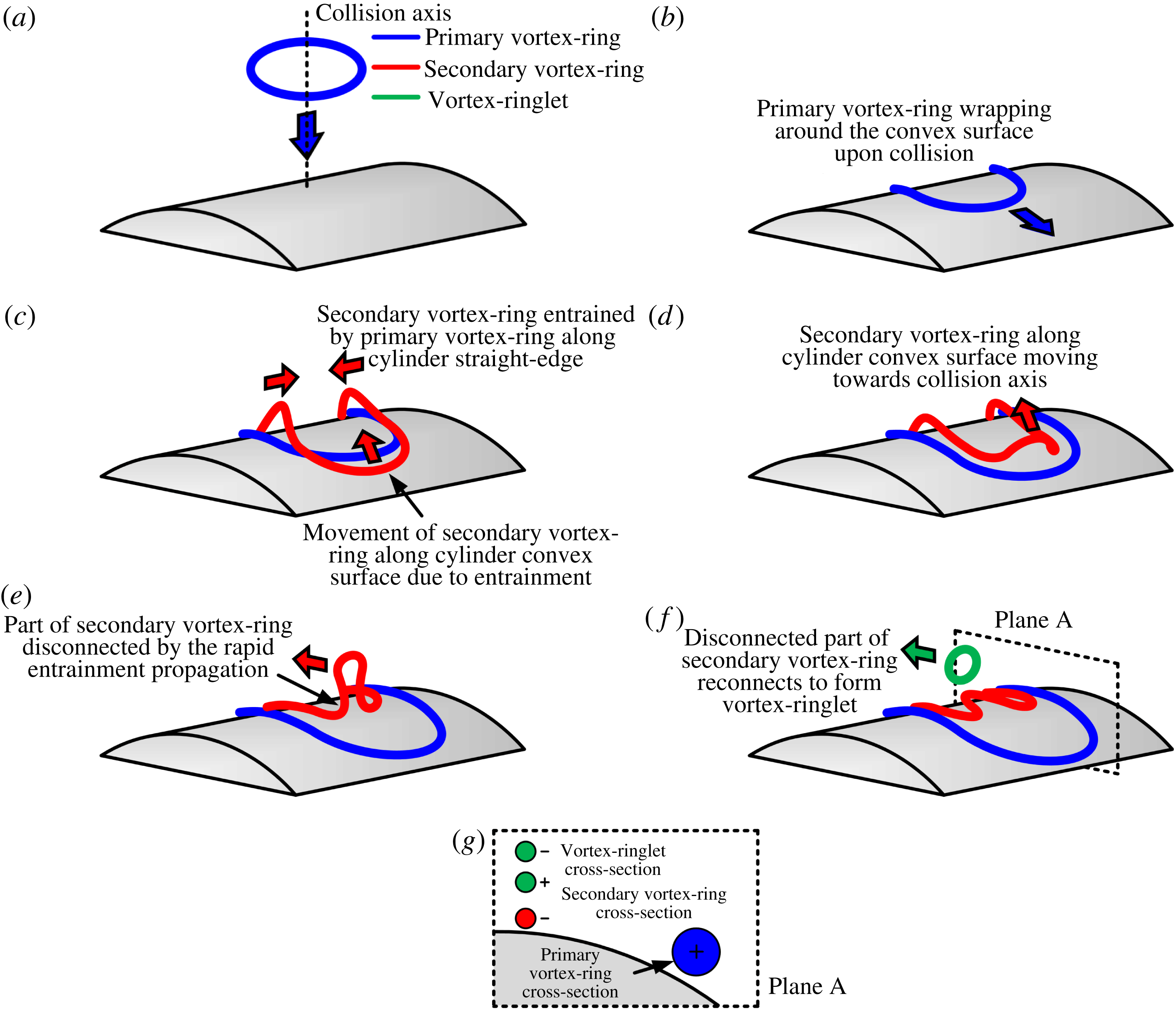
Taking these into account, it is hereby put forward that the outcome of vortex-ring collisions upon round cylinders is dependent upon three main considerations that ultimately point towards the diameter ratio as the most fundamental driving factor – Firstly, the propagation speed at which the primary vortex ring entrains the secondary vortex ring circumferentially. Secondly, the rate at which secondary vortex-ring loops along the convex surfaces are induced to move towards the collision axis by the primary vortex ring and, lastly, the formation location of the secondary vortex-ring loop along the convex surface, which is dependent upon the surface pressure gradient. It is postulated that the above three considerations (and hence diameter ratio) determine where and when selected secondary vortex loops along the convex surface are vortically disconnected from the rest of the secondary vortex ring to form discrete and smaller vortex ringlets that either collide with each other or eject away from the convex surfaces. To better illustrate these postulations and how they will lead to the present experimental observations, vortex flow models based on them for both
 $D/d=4$
and 1 cylinders will now be presented for one-half of the symmetry planes and explained. Note that the vortex flow model associated with the
 $D/d=2$
cylinder is not presented here due to its general resemblance to that for the
 $D/d=1$
cylinder, with the ejected vortex-ringlet trajectories being the primary difference. Also, tertiary vortex rings are not depicted in these flow models, as they do not play significant roles in the flow dynamics seen so far.


Starting with the largest diameter ratio of
 $D/d=4$
shown in figure 19, when the primary vortex ring collides upon the cylindrical surface, a secondary vortex ring with an opposite rotational sense will be formed because of surface boundary layer separations. However, due to non-uniform collision behaviour around the cylindrical surface as the primary vortex ring wraps itself around it, as shown in figure 19(b), the secondary vortex ring will be entrained dissimilarly along the primary vortex-ring circumference. In particular, secondary vortex-ring segments along the cylinder straight edge leapfrog over the primary vortex earlier and faster than corresponding segments along the convex surface, as illustrated in figure 19(c). This is exacerbated by the fact that the primary vortex ring undergoes vortex stretching as it wraps around the cylindrical surface as well. The stronger and more rapid entrainment of secondary vortex-ring segments by the primary vortex ring along the cylinder straight edge means that the former will reside within the boundaries of the latter. On the other hand, entrainment of the secondary vortex ring by the primary vortex ring propagates circumferentially towards segments along the convex surface.
Further along the convex surface, however, secondary vortex-ring segments that resemble two ‘vortex loops’ will move away from the convex surface and towards the collision axis rapidly under the influences of the primary vortex ring, as shown in figure 19(d). As they do so, and near to the collision axis, parts of the secondary vortex loops will draw closer towards each other until they disconnect/reconnect (Kida & Takaoka Reference Kida and Takaoka1994; Gharib & Weigand Reference Gharib and Weigand1996) into two small and distinct vortex ringlets, as can be seen in figure 19(e,f). Since the vortex loops are already moving towards the collision axis in the first place, these two smaller vortex ringlets will meet each other along the collision axis. Subsequently, their collision will cause their diameters to increase, with the top vortex dipole moving upstream along the collision axis. On the other hand, the remaining secondary vortex ring will collapse towards the convex surface and continue to move towards the collision axis. Lastly, to validate the flow model depicted in figure 18, a hypothetical cross-section of the flow field postulated in figure 19(f) along the flow symmetry plane, Plane A, is determined and shown in figure 19(g). It can be deduced that the hypothetical vortex cores associated with the primary and secondary vortex rings, as well as the vortex ringlet, are in excellent agreement with those observed in figures 2(m), 5(a)(iv) and 7(f).
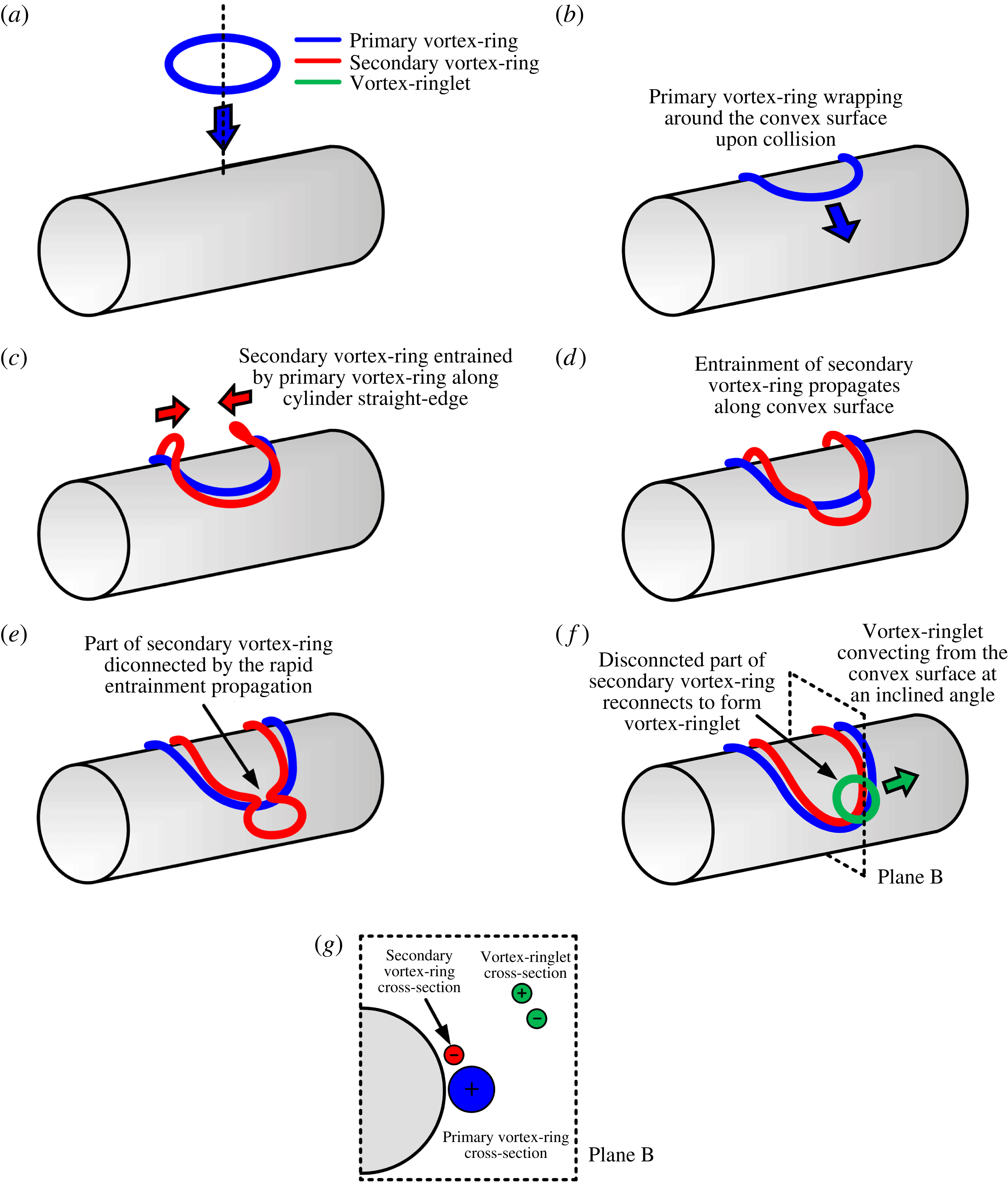
3D sketches of the authors interpretation on the evolution of the primary, secondary and tertiary vortex rings for
 $D/d=1$
. A hypothetical cross-section taken along Plane B of the flow model can be seen to agree well with figures 4(g), 5(c)(iv) and 9(e), if the engulfment of the secondary vortex ring by its primary counterpart is taken into consideration.

The key difference between the flow scenario described for the
 $D/d=4$
cylinder above and the smaller
 $D/d=1$
cylinder shown in figure 20 is that the propagation speed of the circumferential entrainment process will be significantly faster, such that it reaches the primary vortex-ring segments along the convex surface from both sides even before the secondary vortex loops are within close proximity to the collision axis. In this case, they would still be in the process of leapfrogging over the primary vortex ring when the entrainment process reaches close to their locations and pinches them off via vortex disconnection/reconnection processes. As such, the disconnected vortex loops naturally reconnect and form a new vortex ringlet that ejects away from the round cylinder at a certain angle instead, and that will explain the experimental observations seen in figures 3 and 4 earlier. The remaining secondary vortex ring after the vortex disconnection process will eventually be engulfed by the primary vortex ring due to the close proximity between them, as well as the more dominant nature of the primary vortex ring (not shown in figure 20 for clarity). Good agreement between this flow model and earlier experimental results can be observed from the hypothetical cross-sections of the flow field along the flow symmetry plane, Plane B, where primary and secondary vortex cores, as well as the ejected vortex-ringlet cores, are predicted in accordance with the experimental results. Once the diameter ratio is sufficiently small to fall under this flow category, the only apparent impact due to further reductions in the diameter ratio is the angle at which the ejected vortex ring is moving away from the round cylinder, evident in the earlier LIF visualization results when the diameter ratio reduces from
 $D/d=2$
to
 $D/d=1$
.
The above postulation is consistent with the numerical results presented by Ren et al. (Reference Ren, Zhang and Guan2015) with regards to a head-on collision of a vortex ring with a
 $D/d=0.5$
cylinder. Due to the use of a considerably higher Reynolds number and smaller diameter ratio, the dominant vortex structures observed in their
 $Q$
-criterion-based isosurface plots evolve too rapidly to clearly distinguish the vortex disconnection/reconnection process. However, two key supporting observations can be discerned from their simulation results. Firstly, the entrainment of the secondary vortex ring by the primary vortex ring starts from the collision point and propagates further along the convex surface. Secondly, their secondary vortex loops along the convex surface are seen to be left behind after the propagation of the entrainment process. These earlier observations reinforce the notion that it is plausible that new vortex ringlets are produced from the interactions between the primary and secondary vortex rings, with them being ejected away from a round cylinder with a sufficiently small diameter-ratio.
4 Conclusion
An LIF visualization and TR-PIV study reveals that head-on collisions of a vortex ring upon round cylinders with different diameter ratios under the present experimental conditions lead to very different flow phenomena, as compared to their collisions upon conventional flat surfaces. The present study demonstrates that interactions between the primary and secondary vortex rings lead to vortex disconnections and reconnections that subsequently produce smaller-scale vortex ringlets that move in different directions. For a cylinder with a diameter ratio of
 $D/d=4$
, these small vortex rings convect towards the collision axis before they collide head-on with each other to form a vortex dipole that moves back along the collision axis. In contrast, for a cylinder with a smaller diameter ratio of
 $D/d=2$
, earlier formation of the secondary vortex ring leads to correspondingly earlier generation of the small vortex rings. In this case, these vortex ringlets are observed to eject away from the convex surface in a direction that is parallel to but offset at a certain distance from the primary collision axis. As the diameter ratio reduces further to
 $D/d=1$
, greater interactions between the primary and secondary vortex rings give rise to even earlier formation of the small vortex ringlets, which results in the latter ejecting away from the convex surface and inclined approximately
 $60^{\circ }$
away from the collision axis. Note that intense primary and secondary vortex-ring interactions render any tertiary vortex rings formed to undergo rapid transitions into flow incoherence.
On the other hand, vortex-ring collision behaviour as observed along the cylinder straight edges is relatively similar to that associated with classical vortex-ring collision upon a flat surface, regardless of diameter ratio. Secondary and tertiary vortex-core sections are produced and subsequently entrained within the confines of the primary vortex cores. However, due to increased vortex-stretching effects conferred by the convex surface, as well as the formation and ejection of vortex ringlets along the convex plane, the flow behaviour is generally less organized along the straight edge. Additionally, vortex-core trajectories determined from the experimental results reveal the drastically different paths taken by the key vortex structures along the convex surface plane after the vortex ring collides upon cylinders with different diameter ratios. In contrast, corresponding trajectories along the straight-edge plane are relatively insensitive to changes in the cylinder diameter ratio. Circulations of the various vortex-core systems were also estimated from TR-PIV measurements here and compared to those associated with flat-surface collisions. Interestingly, comparisons show that the primary vortex-ring circulations are consistently higher and lower than that resulting from flat-surface collisions with convex surfaces and straight edges, respectively. This observation indicates that vortex-stretching phenomenon is significantly different along the convex surfaces and straight edges, which suggests circumferential flows along the primary and secondary vortex-ring filaments. More importantly, similarities in the circulation levels of key vortex cores observed during the collisions reinforce the notion that they are parts of the same vortex structures, which in this case are the vortex ringlets.
Based on the authors interpretations of the flow visualization and measurement results, three-dimensional vortex flow models for the collision behaviour observed here are presented and discussed. Findings from the present study not only have significant implications on the fundamental behaviour associated with vortex-ring collisions upon round cylinders, they also shed light on possible control over vortex-ring collision or jet-impingement behaviour associated with surfaces of arbitrary curvatures as well. For instance, the trajectories of the vortex dipoles provide clues on the directivity of heat dissipation associated with jet-impingement-based cooling/heating of round cylinders and subsequent thermal management. Furthermore, insights from the present study will also lead to additional understanding on the sizing relationships between the jet nozzle and cylinder sizes, as well as enable formulation of heat transfer strategies that could lead to specifically tailored cooling/heating distributions.
Acknowledgement
The authors gratefully acknowledge the support for this study by the Nanyang Technological University Start-Up Grant, NTU Tan Chin Tuan Exchange Fellowship in Engineering, and Singapore Ministry of Education AcRF Tier-2 grant (MOE2014-T2-1-002). Assistance in the flow visualization experiments by S. Shi, L. Wang and M. Kong at Shanghai Jiao Tong University and programming of the stepper-motor driver by Z. R. Kwan is also greatly appreciated.
Supplementary movies
Supplementary movies are available at https://doi.org/10.1017/jfm.2017.599.