I. INTRODUCTION
Transmitarray antennas are formed by one or more focal sources illuminating a planar array of unit-cells (Fig. 1). Each unit-cell is formed by a receiving antenna, a phase shifting system, and a transmitting antenna. Controlling the transmission phase allows collimating the beam in a desired direction and/or generating radiation patterns with a predefined mask [Reference Hum and Perruisseau-Carrier1]. In the case of reconfigurable transmitarrays, the phase shift of each unit-cell can be controlled electronically using varactor diodes [Reference Boccia, Russo, Amendola and Di Massa2, Reference Lau and Hum3], p-i-n diodes [Reference Clemente, Dussopt, Sauleau, Potier and Pouliguen4, Reference Clemente, Dussopt, Sauleau, Potier and Pouliguen5], micro electro-mechanical systems (MEMS) switches [Reference Chih-Chieh, Lakshminarayanan and Abbaspour-Tamijani6], or tunable materials [Reference Sazegar7]. A limited number of phase states (phase quantization) can be used in order to reduce the complexity of the control logic circuits and to limit the insertion loss due to the active devices integrated in the array.
Schematic views of a transmitarray illuminated by single and multiple focal sources. Cross-section view (a) and rear views (b) for the cross and square source configurations. (c) Simulated broadside realized gains and phase distributions for the single source, square and cross configurations at 10.0 GHz.

These antennas can be used in many defense and civil applications, such as satellite communications, radar systems, wireless metropolitan area networks, point-to-point, and point-to-multipoint communication links.
Their large volume, if compared with phased arrays, could limit the integration on vehicles and on host platforms where a low-profile solution is a primary concern. The thickness of a transmitarray is mainly related to the focal distance, i.e. the distance between the source and the transmitarray receiving layer (labeled F in Fig. 1). The length F is in general several wavelengths in order to optimize the surface illumination. In particular, it should be chosen as a trade-off between the illumination tapering and spillover loss.
In this paper, we demonstrate and validate with numerical simulations and measurements that multiple focal sources can be used to reduce the focal distance F of a transmitarray antenna. The antenna optimized in [Reference Clemente, Dussopt, Sauleau, Potier and Pouliguen5] is considered in this work. Section II presents a sensitivity analysis carried out on this architecture to validate its feasibility; the generation of multiple beams is investigated as well. The experimental validation of the proposed architecture with anechoic chamber measurements is presented in Section III. Finally, conclusions are drawn in Section IV.
II. DESIGN OF THE TRANSMITARRAY WITH MULTI-FEED FOCAL ARRAYS
The reconfigurable transmitarray considered in this work is formed by 400 square unit-cells uniformly distributed in a square arrangement with side D (Fig. 1) and 1-bit of phase resolution. The design, modeling and experimental characterization of this antenna illuminated by a single feed horn have been presented in [Reference Clemente, Dussopt, Sauleau, Potier and Pouliguen4, Reference Clemente, Dussopt, Sauleau, Potier and Pouliguen5].
In [Reference Di Palma, Clemente, Dussopt, Sauleau, Potier and Pouliguen8], we proposed to use four 10 dBi horn antennas as focal sources of this structure placed in two configurations (square and cross) on the focal plane, as illustrated in Fig. 1(b). Only focal arrays of four horns have been considered in order to obtain significant focal distance reduction (about 45% reduction as shown further) while keeping a simple feed network; hence a large number of focal sources would result in a complex feed network and additional losses affecting the whole antenna system efficiency.
The optimization carried out by using the hybrid analytical/numerical analysis approach described in [Reference Kaouach, Dussopt, Lantéri, Koleck and Sauleau9, Reference Clemente, Dussopt, Sauleau, Potier and Pouliguen10] gives an optimal focal distance of F′ = 119 mm (F′/D = 0.39) and a distance between the sources d = 113 mm for the square configuration. In the cross configuration, the optimal values are F′ = 117 mm (F′/D = 0.39) and d = 164 mm. The resulting phase distributions are represented in the insets of Fig. 1(c). In the square configuration, the simulated broadside gain reaches 23.6 dBi at 10.0 GHz (dashed black line in Fig. 1(c)). The 3-dB bandwidth spans from 9.1 to 10.6 GHz. Similar results are obtained for the cross configuration (dashed gray line). From the comparison with the single-source case (solid black line), a slightly higher gain and larger bandwidth are obtained.
A reduction of the focal distance by a factor of about 1.8 (44.4%) is obtained with the multisource illumination with similar performance in terms of maximum broadside gain, 3 dB bandwidth and beamwidth at the cost of increased side lobe levels (SLL). This can be explained by considering the power distributions associated with the incident waves on the receiving layer. The use of four horns, in the cross or square configurations, to illuminate the transmitarray leads to a more uniform power distribution if compared with the single-source case resulting in an increase of the SLL.
The numerical optimization carried out in [Reference Di Palma, Clemente, Dussopt, Sauleau, Potier and Pouliguen8] leads to a configuration in which the distance between the feeds is about 5.4 λ0 (cross) or 3.8 λ0 (square) at 10 GHz; in these conditions, mutual coupling between the feed horns can be neglected. Considering the square configuration (Fig. 1(b)), the phase compensation law on the transmitarray is calculated by considering each horn as a separate source and applying the compensation only to the corresponding quadrant. The resulting phase distribution for the broadside configuration is shown in the inset of Fig. 2(a) (mask B). We obtained a very similar phase distribution compared with the optimized phase distribution (mask A) computed in [Reference Di Palma, Clemente, Dussopt, Sauleau, Potier and Pouliguen8] by considering the four sources contributions. This confirms the low coupling levels and the possibility to assume that each source illuminates a single quarter of the transmitarray.
Simulated radiation pattern at 10.0 GHz in the horizontal plane for the square configuration with the phase optimization method proposed in [Reference Di Palma, Clemente, Dussopt, Sauleau, Potier and Pouliguen8] (mask A) and considering each source independently in each transmitarray quadrant (mask B). Two-beam radiation patterns (at −20° and +30°) obtained by defining different phase distributions on the two sub-arrays in correspondence to the horns 1, 4 (beam at −20°) and 2, 3 (beam at +30°).
As a result of this analysis, the phase distributions on each quarter of the transmitarray can be optimized independently in order to obtain easily multiple beams with the same antenna architecture only by reconfiguring electronically the array. As an example, a phase law to collimate the beam at −20° in the horizontal plane is applied to the two quadrants illuminated by the sources 1 and 4, while sources 2 and 3 are used to generate a second beam at +30° in the same plane (Fig. 2(a)). The generated radiation pattern is shown in Fig. 2(b). The maximum gain of each beam reaches 20.5 and 19.5 dBi, respectively; as compared with the single-beam case, the 3-dB lower gain is due to the fact that only half of the array is used for each beam. The isolation between the two patterns is 20.7 dB at −20° and 16.0 dB at 30°. Up to four beams associated with the four horn antennas (four different channels) can be obtained in any direction and any cut-plane simultaneously enabling spatial multiplexing capabilities for wireless communication applications.
In order to investigate the feasibility of the proposed multisource setup, a sensitivity analysis on the 2 × 2 focal array has been carried out. The square configuration has been considered with the focal source distances optimized at 10 GHz.
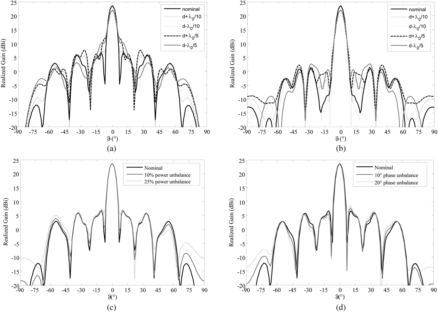
A variation on the source distance d of ±3 mm (λ 0/10 at 10 GHz) and ±6 mm (λ 0/5 at 10 GHz) has been considered. The simulated radiation patterns in the horizontal and diagonal planes are shown in Figs 3(a) and 3(b). With a variation of +3 mm, the maximum broadside gain is 23.2 dBi, 0.4 dB below the nominal case. The SLL increases by about 1 dB in the horizontal plane. A gain of 23.1 dBi is obtained for the −3 mm variation and the SLL is −14.6 dB. Increasing the position error to +6 mm, the maximum gain is reduced to 22 dBi with SLL of −14.5 dB. In the last case (d-6 mm), the gain is 21.9 dBi and the SLL is −11.6 dB in the horizontal plane. Therefore, an error of ±3 mm in the source position produces a gain variation lower than 0.5 dB with of 2.4 dB higher SLL. Similar results are obtained for the cross configuration and show a good robustness of the antenna architecture with respect to the source position errors.
Simulated radiation patterns (realized gain) for the square configuration at 10 GHz. Results obtained by varying the source positions by 3 and 6 mm in (a) horizontal and (b) diagonal planes; Simulated radiation patterns when varying the source excitation in magnitude (c) and phase (d) in the horizontal plane. The optimal phase distribution shown in Fig. 2(a) is used in all these simulations.
In the proposed design, the four horn antennas are excited coherently with signals of equal amplitude and phase. These excitations can be realized with a simple feeding network based on three power splitters which can be implemented in various technologies. In any practical case, the output signals suffer from unbalances in magnitude and phase. The effects of these errors on the radiation performances are discussed here for the first time with a proper simulation study by considering the four horns in the square configuration.
First, a power unbalance between the focal sources 1, 3 and 2, 4 (see Fig. 1(b)) of 10% (±0.2 dB) is considered. The obtained radiation pattern in the horizontal plane is shown in Fig. 3(c) (gray bold line). Compared with the nominal case (black bold line), the side lobes at ±55° vary in opposite sense by ±1 dB. However, the maximum SLL remains similar to the nominal case, since the first side lobes are almost unchanged by this variation. The radiation pattern on the orthogonal plane is identical to the nominal case. Increasing the amplitude unbalance to 25% (±0.45 dB), the side lobe at −55° increases by 2.5 dB as shown in Fig. 3(c) (black line) and the first side lobe is 0.8 dB higher.
A phase unbalance is considered for the same setup. As shown in Fig. 3(d), the radiation pattern presents a SLL increased by 1.2 and 2.2 dB for 10° and 20° of phase difference, respectively, applied between the sources 1, 3 and 2, and 4 (see Fig. 1(b)). The maximum gain decreases by 0.1 and 0.2 dB in these two cases, respectively. The same unbalances in magnitude and phase applied between the sources 1, 4 and 2, 3 produce similar effects on the radiation patterns on the vertical plane. It can be concluded that the sensitivity to magnitude and phase unbalances of this antenna architecture can be easily managed using classical microwave circuits.
III. EXPERIMENTAL RESULTS
The transmitarray with the four-source configurations has been characterized in anechoic chamber (Fig. 4). The radiation patterns have been measured in co- and cross-polarizations for each focal source successively. The total co- and cross-polarization components are then reconstructed by combining coherently (i.e. in magnitude and phase) the radiation patterns measured for each source. In that way, no power splitter is needed, avoiding additional losses and measurement uncertainties (unbalanced amplitude and phases) related to these components. For actual applications, the feeding network must be included in the design and taken into account in the phase compensation calculations. However, these aspects go beyond the objectives of this work.
Photographs of the experimental setup used for the characterization of the reconfigurable transmitarray (a). Single horn configuration with F = 214 mm (b); four-horn configuration with F′ = 119 mm (square configuration) (c).
The measured frequency responses of the transmitarray in the two multisource configurations are plotted in Fig. 5(a). The corresponding phase distributions are reported in the insets of Fig. 2(a). A good agreement with the simulated results can be observed. The 3 dB gain bandwidth is 9.1−10.6 GHz (15.2%).
Measured and simulated broadside realized gain (a) for the cross and square configurations. Measured and simulated radiation pattern in the E-plane (φ = 0°) (b) for the square configuration.
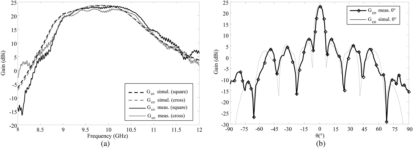
The radiation pattern measured at 10 GHz for the square configuration is represented in Fig. 5(b). The maximum measured gain is 23.2 dBi with a SLL of −14.4 dB. A very good agreement in the main beam region with the simulated results has been found. The minor differences in the angular region 15°–70° can be attributed to the measurement uncertainties including millimetric errors in the horn positioning on the focal plane. Discrepancies outside this range can be attributed to spillover radiation and scattering on the array edges is not taken into account in the numerical analysis.
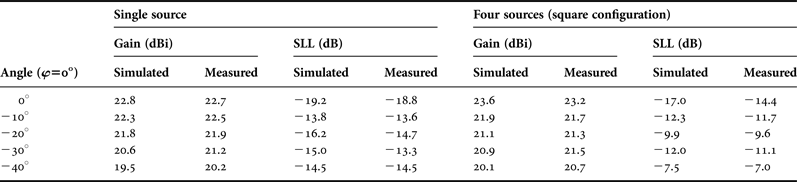
Tilted-beam configurations in the two cardinal planes have been measured up to 40°, with the corresponding phase distributions calculated by considering the proper phase delay. In the square configuration, the radiation pattern pointing at −10° in E-plane (φ = 0°) is shown in Fig. 6(a). The maximum gain is 21.7 dBi with a SLL of −11.7 dB. The radiation patterns with −20°, −30° and −40° of tilting angles are shown in Figs 6(b)–6(d). The maximum gain and the SLL values are reported in Table 1. Similar results are obtained for the cross configuration, as shown in Figs 6(e)–6(h). The frequency dependence of the radiation pattern (co-polarization component) is illustrated in Fig. 7 with broadside and tilted beams at −20° and −40° in E-plane (φ = 0°) for the square configuration. The large bandwidth of the transmitarray can be observed and the SLL do not vary significantly across the entire bandwidth between 9.1 and 10.6 GHz. The variation of the main beam direction (beam-squint) is ±2° in these cases. The cross-polarization discrimination is always higher than 30 dB in the main beam direction in all the tested cases.
Measured and simulated radiation patterns (realized gain) for the square (a, b, c, d) and cross (e, f, g, h) configurations with −10° (a, e), −20° (b, f), −30° (c, g) and −40° (d, h) tilted beams in E-plane (φ = 0°). The corresponding phase distributions are shown in the insets.
Measured radiation patterns of the reconfigurable transmitarray with four focal sources (square configuration) between 8 and 12 GHz with broadside (a) and tilted beams at −20° (b) and −40° (c) in E-plane (φ = 0°).
Gains and SLL for the reconfigurable transmitarray with four horns as focal source (square configuration) compared with the single-source case.
IV. CONCLUSION
The design and experimental characterization of a reconfigurable transmitarray in X-band with reduced focal distance has been presented. Two focal array configurations have been considered: cross and square configurations. A sensitivity analysis on the source positions and excitations is presented. Generation of multiple beams with the proposed architecture has been discussed and demonstrated numerically in the case of two beams at −20° and 30° in the horizontal plane. The radiation measurements show a maximum broadside gain of 23.2 dBi at 10 GHz with SLL below −14.4 dB in the square configuration with a focal distance of 119 mm (F/D = 0.39). The radiation patterns with a single beam and several tilting values up to −40° in both configurations have been studied, and a good agreement between measurements and numerical results has been obtained. A reduction of the focal distance by a factor 1.8 (44.5%) has been confirmed experimentally, maintaining at the same time good radiation performances.
A further reduction of the total size of the system could be achieved by considering focal sources in planar technologies (e.g. substrate integrated waveguide, microstrip, etc.) instead of horn antennas. The reduction of SLL could be also investigated in a future work by considering an amplitude tapering law in the transmitarray unit-cell distribution.
ACKNOWLEDGEMENT
This work was partly supported by the French Ministry of Defence with the Direction Générale de l'Armement (DGA).
Luca Di Palma was born in Rome, Italy, in 1987. He received his B.S. degree in Electronic Engineering (summa cum laude) and the M.S. degree in ICT Engineering (summa cum laude) from the University of Roma Tre, Rome, Italy, in 2009 and 2011, respectively. He is presently pursuing the Ph.D. degree in signal processing and telecommunication systems at the University of Rennes 1, Rennes, France. His Master Thesis project on the design of waveguide components loaded with metamaterials has been awarded with a special mention at the Marconi Junior Prize in 2012. Since January 2013, he has been a research assistant with CEA, LETI, Grenoble, France. His research interests include metamaterials, reconfigurable antennas, array and quasi-optic array antennas at microwave frequencies.
 Antonio Clemente received his B.S. and M.S. degrees in Telecommunication Engineering and Remote Sensing Systems from the University of Siena, Italy, in 2006 and 2009, and the Ph.D. degree in Signal Processing and Telecommunications from the University of Rennes 1, France, in 2012. From October 2008 to May 2009 he realized his master thesis project at Technical University of Denmark (DTU), Lyngby, Denmark, where he worked on spherical near-field antenna measurements. His Ph.D. has been realized at CEA-LETI, Grenoble, France. In 2012, he joined the R&D laboratory of Satimo Industries, Villebon-sur-Yvette, France. Since 2013, he is a Research Engineer at CEA-LETI, Grenoble, France. His present research interests include quasi-optic reconfigurable antennas at microwave and millimeter-wave frequencies, miniature integrated antennas, near-field and far-field antenna measurements. Dr. Clemente received the Young Scientist Awards (First Prize) during the 15th International Symposium of Antenna Technology and Applied Electromagnetics 2012 (ANTEM 2012) in Toulouse, France.
Dr. Laurent Dussopt received the Ph.D. degree in Electrical Engineering from the University of Nice-Sophia Antipolis, France, in 2000, and the “Habilitation à Diriger des Recherches” degree from the University of Grenoble, France, in 2008. From September 2000 to October 2002, he was a Research Fellow with The University of Michigan at Ann Arbor where he developed reconfigurable microwave circuits and antennas based on RF-MEMS technology. Since 2003, he has been with CEA-LETI, France, as a Research Engineer and project leader on radio and antenna systems. Since 2013, he is chief scientist of the Systems and Integration Solutions division of CEA-LETI. Since 2014, he coordinates the EU project MiWaveS. Dr. Dussopt has published more than 150 scientific papers in international journals and conferences and several book chapters, and is a senior member of IEEE. His research interests include mainly advanced antenna systems for wireless communications at microwave and millimeter-wave frequencies.
Ronan Sauleau (M'04–SM'06) graduated in Electrical Engineering and Radio Communications from the Institut National des Sciences Appliquées, Rennes, France, in 1995. He received the Agrégation degree from the Ecole Normale Supérieure de Cachan, France, in 1996, and the Doctoral degree in Signal Processing and Telecommunications and the “Habilitation à Diriger des Recherches” degree from the University of Rennes 1, France, in 1999 and 2005, respectively. He has been appointed as a full Professor in the same University since November 2009. He has been involved in more than 30 research projects at the National and European levels and has co-supervised 14 post-doctoral fellows, 24 Ph.D. students and 40 master students. He has received eight patents and is the author or coauthor of more than 160 journal papers and 360 publications in international conferences and workshops. He has shared the responsibility of the research activities on antennas at IETR in 2010 and 2011. He is now co-responsible for the Research Department “Antenna and Microwave Devices” at IETR and is the deputy director of IETR.
Patrick Potier received his Ph.D. degree in Structure and Property of the Material from the University of Rennes, Rennes, France, in 1984. From September 1984–1987, he was a research engineer with Thomson CSF, Paris, France. Since September 1987, he has been an Engineer with the Center Maîtrise de l'information (Information superiority) de la Direction Générale de l'armement (General Armaments Directorate, the French procurement agency), Bruz, France. He treats the aspects of antennas and radiation and ensures the follow-up of various studies and theses mainly on the topics broad band reflect or transmit arrays.
Philippe Pouliguen received his M.S. degree in Signal Processing and Telecommunications, the Ph.D. l degree in Electronics and the Habilitation à Diriger des Recherches degree from the University of Rennes 1, Rennes, France, in 1986, 1990, and 2000, respectively. In 1990, he joined the Direction Générale de l'Armement (DGA) at the Centre d'Electronique de l'Armement (CELAR), now DGA Information Superiority (DGA/IS), Bruz, France, where he was a DGA Expert in electromagnetic radiation and radar signatures analysis. He was also in-charge of the EMC (Expertise and ElectoMagnetism Computation) laboratory of CELAR. Since December 2009, he has been the Head of the acoustic and radio-electric waves scientific domain at the office for Advanced Research and Innovation of the Strategy Directorate, DGA, Bagneux, France. His research interests include electromagnetic scattering and diffraction, radar cross section (RCS) measurement and modeling, asymptotic high frequency methods, radar signal processing and analysis, antenna scattering problems, and electronic band gap materials. In these fields, he has published more than 30 articles in refereed journals and more than 100 conference papers.