I. INTRODUCTION
Owing to their excellent properties at elevated temperatures, Ni-based single crystal superalloys are widely used for turbine blades and guide vanes of advanced aero-engines and industrial gas turbines.Reference Reed1–Reference Graverend, Jacques, Cormier, Ferry, Schenk and Mendez4 To obtain higher turbine entry temperatures, the geometry of blades became more complex with some complex air-cooling channels. Besides, more refractory elements were added to improve the high temperature performance of the superalloys.Reference Yeh and Tin5 However, these improvements were always accompanied by a greater frequency of solidification defects, such as freckles chains,Reference Tin, Pollock and Murphy6,Reference Li, Shen, Qin and Gao7 stray grains,Reference Vehn, Dedecke, Paul, Sahm, Kissinger, Deye, Anton, Cetel, Nathal, Pollock and Woodford8,Reference Yang, Dong, Wang and Lee9 sliver defectsReference Aveson, Tennant, Foss, Shollock, Stone and D’Souza10 and low-angle grain boundaries (LABs).Reference Newell, D’Souza and Green11,Reference Bogdanowicz, Albrecht, Sieniawski and Kubiak12 Among these defects, LABs is detrimental to the mechanical properties, especially when the misorientation angle is larger than 9°,Reference Li, Zhao, Liu, Han, Reed, Green, Caron, Gabb, Fahrmann, Huron and Woodard13,Reference Zhao, Li, Liu and Han14 because the grain boundaries (GBs) may be the weakest points at high temperatures due to the absence of GB-strengthening elements in the Ni-based single crystal superalloys.
Over the past two decades, some studies were carried out to investigate the formation mechanism of LABs. In 2000, Napolitano et al.Reference Napolitano and Schaefer15 developed a tip-growth model to simulate the dendrite growth, established a convergence-fault criterion for the location of LABs, and pointed out that the formation of LABs was due to the gradual accumulation of slight orientation deviation in the process of dendrite branching and growth. However, the reasons for the orientation deviation were not clarified. After that, Newell and Souza et al.Reference Newell, D’Souza and Green11,Reference Newell, Devendra, Jennings and D’Souza16,Reference Newell, D’Souza and Green17 used different casting models to study the formation of LABs in Ni-based superalloys. The results showed that steady state growth led to a random misorientation and non-steady state conditions caused an accumulated misorientation which subsequently produced LABs when the dendrite fronts impinged. They attributed this misorientation to the plastic deformation of the dendrites within the mushy zone. In fact, as early as in 1993, Siredey et al.Reference Siredey, Boufoussi, Denis and Lacaze18 found that crystalline quality could decrease because of the misorientation in initial dendrites themselves and proposed that the thermomechanical stresses induced by the precipitation of the γ′ could be high enough for the plastic deformation of the dendrites. In 2014, Bogdanowicz et al.Reference Bogdanowicz, Albrecht, Sieniawski and Kubiak12 investigated the subgrain structure in single crystal turbine blade roots; they reported that the formation of LABs was caused by the inclined growth of secondary dendrite arms and concluded that the reason might be the element segregation around boundaries disturbing the lattice parameters. In addition, some researchers suggested that the liquid flow between dendrites might also cause the dendrite deformation.Reference Dragnevski, Mullis, Walker and Cochrane19 It was clear that the formation of LABs was very complicated and the leading reasons might be different under various solidification conditions. However, previous studies on the formation mechanism of LABs were usually under a certain solidification condition, and some investigations about the formation of LABs at different withdrawal rates were based on turbine blades,Reference Wang, Wu, Huang, Ma, Jakumeit and Bührig-Polaczek20 especially almost no studies were aimed at the castings with rejoined structures, such as nozzle guide vane,Reference Newell, Devendra, Jennings and D’Souza16 double guide vane and grain continuator,Reference Ma21 whose geometries were conducive to the branching and convergence of dendrites.
In the present work, a model with rejoined platforms was designed to systematically investigate the formation of LABs under different solidification conditions through experiments and finite element simulation methods. It is expected to show the dendrite patterns under different solidification conditions, to investigate the reasons for orientation deviation under different solidification conditions, to clarify the relationship between the formation of LABs and dendritic patterns, and finally to establish the relationship between the formation of LABs and the solidification conditions in the rejoined platforms.
II. EXPERIMENTAL AND SIMULATION METHODS
A. Experiment details
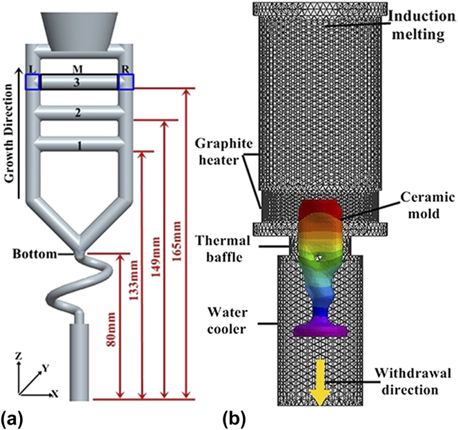
Directional solidification experiments were carried out using the traditional high rate solidification (HRS) method. The Ni-based superalloy DD6 was used in the experiments, with the nominal composition of 4.3 Cr, 9.0 Co, 2.0 Mo, 8.0 W, 7.5 Ta, 5.6 Al, 2.0 Re, 0.5 Nb, 0.1 Hf, 0.006 C, and Ni balance in wt%. The model with rejoined platforms was used to prepare single crystal castings. From bottom to top, the platforms were numbered in sequence and each platform was divided into three areas—left (L), middle (M), and right (R)—as shown in Fig. 1(a).
Schematic of the sample assembled with a spiral grain selector (a) and the FEM mesh model of the casting system (b).

The single crystal castings were prepared using a modified Bridgman directional casting furnace. The furnace consists of a vacuum-induction melting unit, a graphite heating unit and a cooling zone, as shown in Fig. 1(b). During the casting process, the ceramic mold was mounted on a water-cooled copper chill plate and was then raised into a cylindrical graphite heater, and then the furnace chamber was evacuated and the mould was preheated to 1540 °C. After equalizing the mold temperature, the molten superalloy DD6 (1580 °C) was poured into the mould and held for 15 min. Finally, the ceramic mold was withdrawn from the furnace at a predetermined withdrawal rate: 60, 75, and 100 μm/s, respectively.
After the castings were cleaned up, the riser and the spiral grain selectors were removed by wire electrodischarge machining, and a transverse cross section (parallel to the XY surface) was cut at the bottom position; meanwhile, the rejoined platforms were sectioned from the castings longitudinally (parallel to the ZX surface) and transversely (parallel to the XY surface). Then the specimens were polished well and etched with a solution of HNO3, HF and C3H8O3 (volume ratio of 1:2:3.5) for optical microscopy. The microstructure was observed with an optical microscope (OM; Leica DM-4000 M, Leica, Berlin, Germany).
Orientation determination of the dendrites was performed using the electron back-scattering diffraction (EBSD) technique. After the samples were mechanically polished to remove stress and obtain a flat surface, EBSD measurements were performed in a Tescan Mira 3 XMU scanning electron microscope (SEM; TESCAN VEGA, TESCAN, Brno, Czech Republic) equipped with the HKL system and Channel 5 analysis software (Oxford Instruments, Oxford, U.K.). A step size of 40 μm was used for EBSD mapping.
B. Simulation methods
To exhibit the thermal profile and assess the transient stresses and strains evolved during the directional solidification process, the castings were simulated using finite element analysis by ProCAST software (CalcomESI, Lausanne-EPFL, Switzerland).Reference Gandin, Rappaz and Tintillier22
Finite element mesh models of casting and the ceramic shell were constructed into a 3D mesh, and the furnace was constructed into a 2D mesh, as shown in Fig. 1(b). The initial state of simulation was after the holding process, the melt temperature was set to 1550 °C, and the chill-plate temperature was 400 °C. During the withdrawal process, the heat transfer was assumed to be heat conduction and radiation and heat convection was ignored. The radiation heat transfer was calculated by a radiation algorithm taking into account reflections, obstructions and shadowing effects. The coefficients of thermal emissivity and thermal conductivity were gained from Refs. Reference Miller and Pollock23–Reference Brundidge, Miller and Pollock27. The thermophysical parameters were calculated by ProCAST and the thermodynamic software JMatPro (Sente Software Ltd., Surrey, UK). The initial conditions, the boundary conditions and the interface heat transfer coefficients were listed elsewhere in Ref. Reference Huo, Liu, Yang, Sun, Hu, Zhang and Fu28.
During the simulation of stress field, it was assumed that the solidified metal was with isotropic hardening and elastoplastic constitutive relation, the ceramic shell was treated as a rigid solid and thus with no deformation, and the creep and fracture were also ignored. At near-melting temperatures, the creep allowed stress relaxation. Therefore, the calculated stresses were overestimated. Besides, the model was run as sequential, uncoupled, thermomechanical analysis. A continuum approximation was used; therefore, microstructural issues were necessarily ignored.
III. RESULTS AND DISCUSSIONS
A. The LABs derived from the orientation deviation of original primary dendrites at lower withdrawal rate
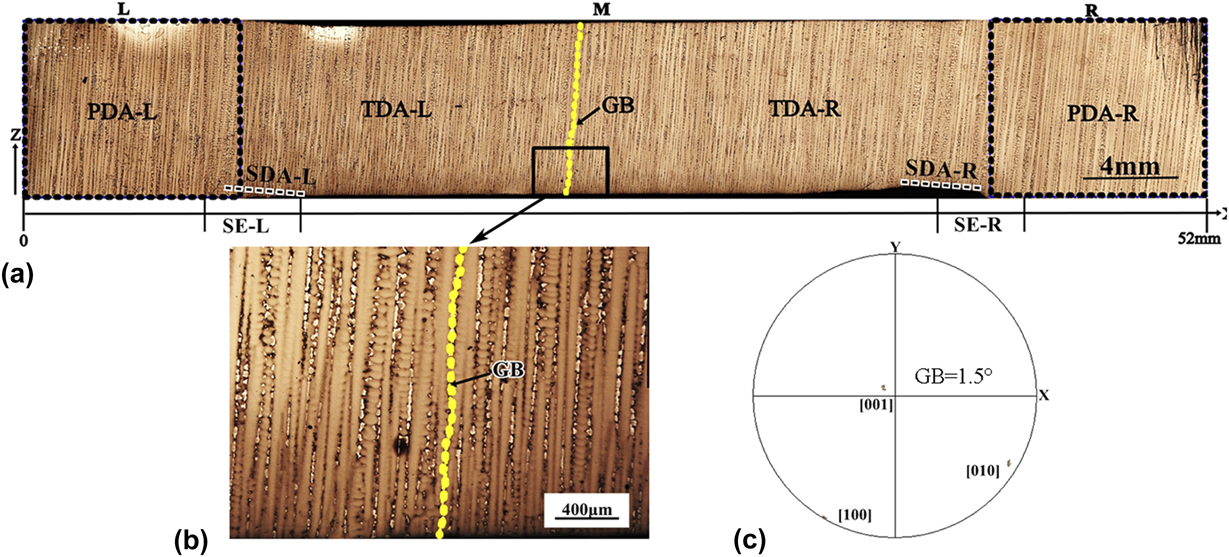
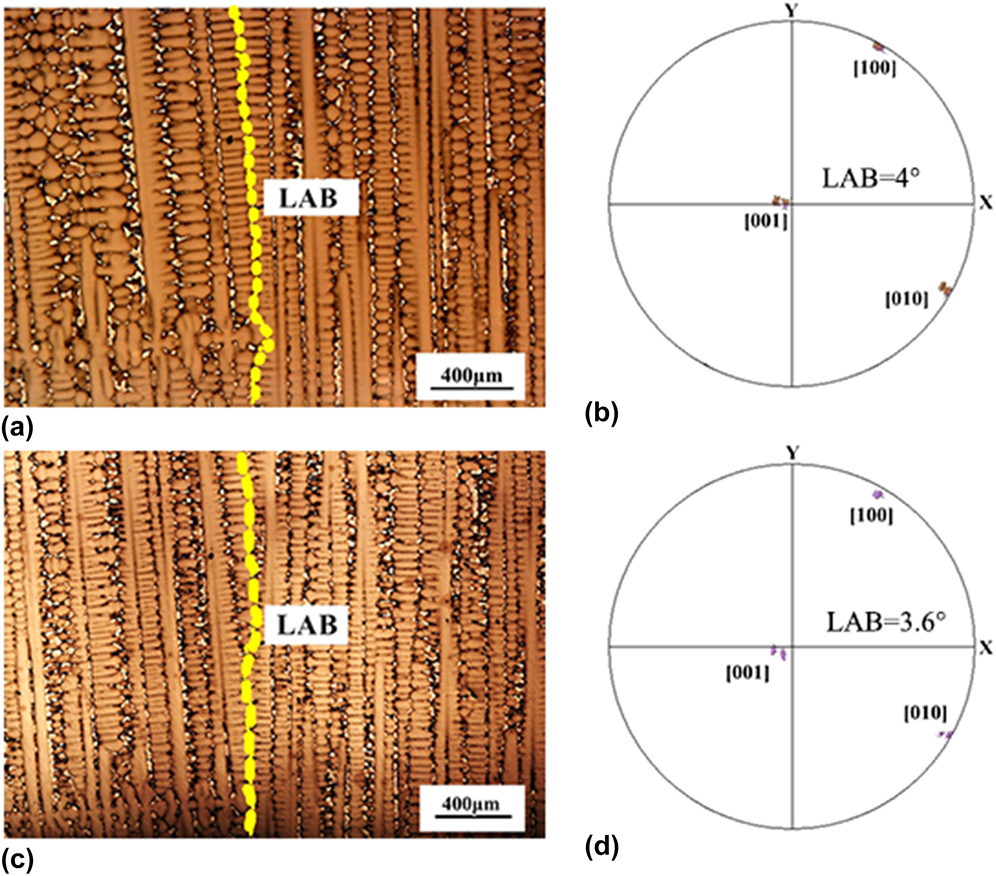
Figure 2(a) shows dendritic structures of longitudinal section (parallel to the ZX surface) of the entire platform 1 at the withdrawal rate of 60 μm/s. The dendritic structures of regions L and R were similar because they were from the branching of original dendrites from the spiral grain selector. The primary dendrite arms (PDA-L and PDA-R) grew regularly. When the dendrites grew into the section extension region (SE: SE-L and SE-R), some long secondary dendrite arms (SDA-L and SDA-R) formed at the bottom of the platform, as shown as the dotted line in regions SE-L and SE-R in Fig. 2(a), and they became the base for ternary dendrite arms TDA-L and TDA-R. Finally, the TDA from both sides occupied the entire platform. In this process, a GB formed when TDA-L and TDA-R encountered, as shown as the dotted line in Figs. 2(a) and 2(b). If the angle of GB was larger than 2°, it was a LAB. In platforms 2 and 3, their dendrite evolutions were similar to that of platform 1, and there were also GBs at the encounter position of dendrites, as shown in Figs. 3(a) and 3(c). Their corresponding polar diagrams in Figs. 3(b) and 3(d) indicated that these GBs were LABs.
Optical micrographs of the entire platform 1 for the longitudinal section at the withdrawal rate of 60 μm/s (a), magnified local micrograph of GB (b), and its corresponding polar diagram (c).

Microstructure at the convergence of dendrites of platform 2 (a) and platform 3 (b), the corresponding polar diagram (c) for platform 2, and the polar diagram (d) for platform 3 at the withdrawal rate of 60 μm/s.

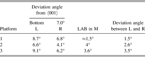
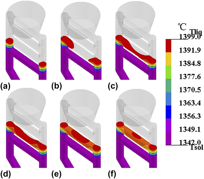
To determine the evolution of original orientation with height and the relationship between the LABs and the original dendrites from both sides L and R, the crystal orientation at the bottom position and the orientations of PDA-L and PDA-R of the three platforms were all measured. The misorientation angles are analyzed in Table I. The results showed that after the process of crystal selection, the crystal orientation at the bottom was not a strict 〈001〉 direction, and the original orientation of both sides fluctuated with the increase of height, and the angles of LABs were close to the deviation angles between L and R. In other words, the LABs were mainly caused by the fluctuations of the original orientation of PDA-L and PDA-R. Therefore, the original orientation deviations might be a very important concern. From the data in Table I, it could be seen that the original deviation angles from 〈001〉 were different and there was no accumulation from platform 1 to 3 as the height increased, which was different from the experimental results of Siredey,Reference Siredey, Boufoussi, Denis and Lacaze18 who proposed that misorientation was due to the thermomechanical stresses. In fact, the random orientation fluctuations might be natural in the growth of a single crystal because the complex geometry might lead to a nonuniform thermal field and the curvature fluctuation of solid–liquid interface, especially in region SE, as shown by the evolution of the temperature field in Fig. 4. Obviously, the isotherm shapes varied at different solidification times in Figs. 4(a)–4(f). Previous studies indicated that these unstable thermal factors in the directional solidification might lead to the orientation deviation of dendrites during their growth.Reference D’Souza, Ardakani, Mclean and Shollock29 The deviated dendrites might be more likely affected by the solidification conditions because they were not parallel to the heat flow and the local thermal field. In this sense, if the original orientation could be strictly along the 〈001〉 direction, this effect might be weakened and the LABs in the middle region of the platforms might be avoided. Fortunately, the angle of such LABs was small and generally within tolerance limits, and thus they were often ignored. However, if some high temperature properties were very sensitive to the deviation, the original orientation of the dendrites had to be controlled strictly.
Misorientation data of the platforms.

The isotherm shapes at different solidification times in the rejoined platform at the withdrawal rate of 60 μm/s (a) 2244 s, (b) 2314 s, (c) 2324 s, (d) 2334 s, (e) 2344 s, and (f) 2354 s.

B. The LABs introduced by slivers
In the rejoined platforms, another type of longitudinal LABs was introduced by sliver defects. Of all castings in the experiments, there was a sample with sliver defects in all rejoined platforms The slivers occurred mainly in two locations: regions SE and M. Figure 5(a) showed the dendritic structure of longitudinal section (parallel to the ZX surface) of the whole platform with sliver defects and the magnified local micrograph of the sliver region. The dendrite evolution was similar to that in Fig. 2. However, there were solidification defects that occurred in two positions: (i) two deviating dendrites A and B with misorientation less than 10° formed in the right section extension (SE-R), (ii) a sliver, the dendrites TDA-RII formed in region M of the platform. This study had been published in the previous work.Reference Huo, Liu, Yang, Sun, Hu, Zhang and Fu28
Longitudinal optical micrograph of the platform with sliver defects and the magnified local micrograph at the withdrawal rate of 75 μm/s (a), and its corresponding polar diagrams (b) and (c).

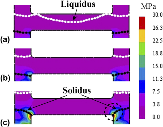
Firstly, Fig. 5(b) was the pole figure of the three groups—grain A, grain B and original dendrites—and it showed that they had close [010] positions and varied [001] positions. It indicated the sense of mainly rotation of 〈001〉 directions, and there also might be bending because their [010] directions were not exactly identical. In other words, the dendrites had undergone both torsion and bending deformations in region SE. Therefore, the two deviating dendrites A and B were the results of the dendrite deformation in region SE. Furthermore, the stress distribution of the platform in Fig. 6 indicated that region SE was a stress concentration area and was beneficial to dendrite deformation in this region. Besides, the long secondary branches in region SE could be regarded as some cantilever beams, and they were relatively fragile at the mushy stage and were prone to deformation due to contraction stress. The deformed dendrites eventually survived after solidification.Reference Aveson, Tennant, Foss, Shollock, Stone and D’Souza10,Reference Newell, D’Souza and Green17
Total effective stress evolution with the advancing of liquidus (white dotted line) and solidus (black dotted line) in the platform during solidification process: (a) t = 1924 s, (b) t = 1964 s, and (c) t = 2004 s.

Secondly, it was found that the sliver in region M might originate from the continuous growth of deformed dendrites B in region SE-R. The reasons are as follows: (i) comparing the pole figure of sliver region in Fig. 5(c), it was found that the orientation of sliver in region M was the same as that of grain B; (ii) the stress field in region M was not conducive to dendrite deformation in this region, as shown in Fig. 6; (iii) in region SE, the long secondary branches could grow into a platform, as shown by the dotted line in the magnified local micrograph of the sliver region in Fig. 5(a); and (iv) grain B might also grow into a platform through a competitive growth, and there was an insertion or even a corresponding lateral motion between dendrites, as shown by grain B in the magnified local micrograph in Fig. 5(a), which was common in competitive growth and was believed to be the main mechanism for overgrowth.Reference Hu, Yang, Cui, Huang, Zhang and Liu30,Reference Zhou and Sun31 This meant that although the deformed dendrites could be blocked by their adjacent dendrites in the test cross section, they might continue to grow into the platform in other directions.
Finally, the deformation of secondary branches occurred in the stress concentration region SE and continued to grow into the platform to form a sliver through the competitive growth with the adjacent dendrites. The boundaries of these slivers were LABs. It should be noted that the concept of “sliver” was based on the macroscopic morphology of this kind of solidification defect. In fact, the slivers might be more like a subgrain and the boundaries were LABs if the boundary angle was 2–15°; if the angle was more than 15°, the defect might be classified as a stray grain.
C. The LABs accompanied by severe lateral growth of the secondary dendrites at higher withdrawal rate
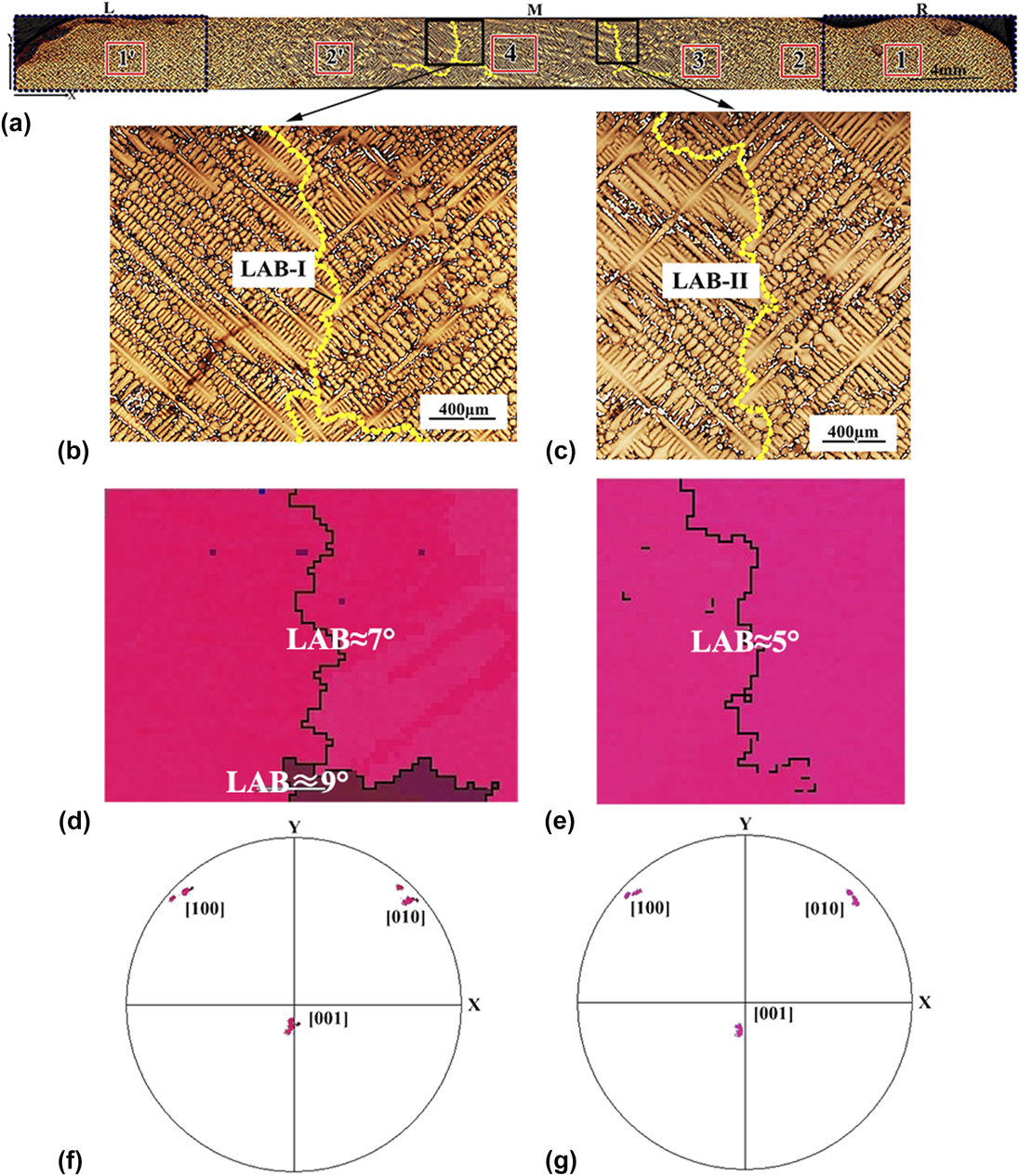
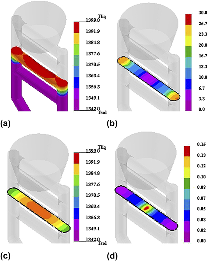
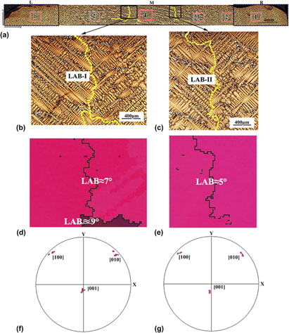
The above two types of LABs were easily found on the longitudinal sections of the casting, especially after macro-etching. However, in some specimens, the growth of dendrites in the longitudinal sections was perfect without defects, while some LABs were found in their transverse sections, especially when the lateral growth was severe and the growth paths of the dendrites were complex. Figure 7(a) showed the dendritic structure of transversal cross section (parallel to the XY surface) of the whole platform with LABs accompanied by severe lateral growth of the secondary dendrites at the withdrawal rate of 100 μm/s. In regions L and R, the dendrites were of typical cruciform structure and arraying regularly. After that, the secondary branches in both sides showed a lateral growth and became gradually serious until the middle of region M. It might be caused by the substantial lateral heat extraction in this region. Figure 8(a) shows the isotherm shapes at the beginning of solidification in region M. Obviously, the isotherm shape was concave and looks like an ellipsoidal surface, and it was propitious for lateral heat dissipation. Besides, the temperature gradients in the different regions of the platform were different, as shown in Fig. 8(b). Previous studies have shown that the solid–liquid interface would be more concave and obviously lag under higher withdrawal rate, and the temperature gradient and its direction would change accordingly, leading to the dispersion of crystal orientation.Reference D’Souza, Ardakani, Mclean and Shollock29,Reference Miller and Pollock32,Reference Miller, Yuan, Lee and Pollock33 Furthermore, due to the different curvature of the isotherm and the inhomogeneous thermal field in Fig. 8(c), the growth rates of dendrites in different regions were also fluctuating, as shown in Fig. 8(d); thus the orientation of dendrites in different regions changed during growth. Finally, these secondary branches of the lateral growth with different orientations produced boundaries once they converged, as shown in Figs. 7(b) and 7(c). Their corresponding EBSD scan maps in Figs. 7(d) and 7(e) and the polar diagrams in Figs. 7(f) and 7(g) indicated that the boundaries were LABs. Similar phenomena can be found in the literature,Reference Wang, Wu, Huang, Ma, Jakumeit and Bührig-Polaczek20,Reference Miller and Pollock32,Reference Zhang, Zhou, Han, Jin and Sun34 especially for castings with large cross sections which were beneficial to lateral heat extraction.
Transverse optical micrographs of the platform with LABs accompanied by severe lateral growth at the withdrawal rate of 100 μm/s (a), magnification diagram of LAB-I (b) and LAB-II (c), their corresponding EBSD scan maps (d) and (e), and polar diagrams (f) and (g).

The isotherm shapes at the withdrawal rate of 100 μm/s, simulation time t = 1490 s (a), the temperature gradient (b), thermal field in the transverse section of the platform (c), and solidification rate of the platform (d).

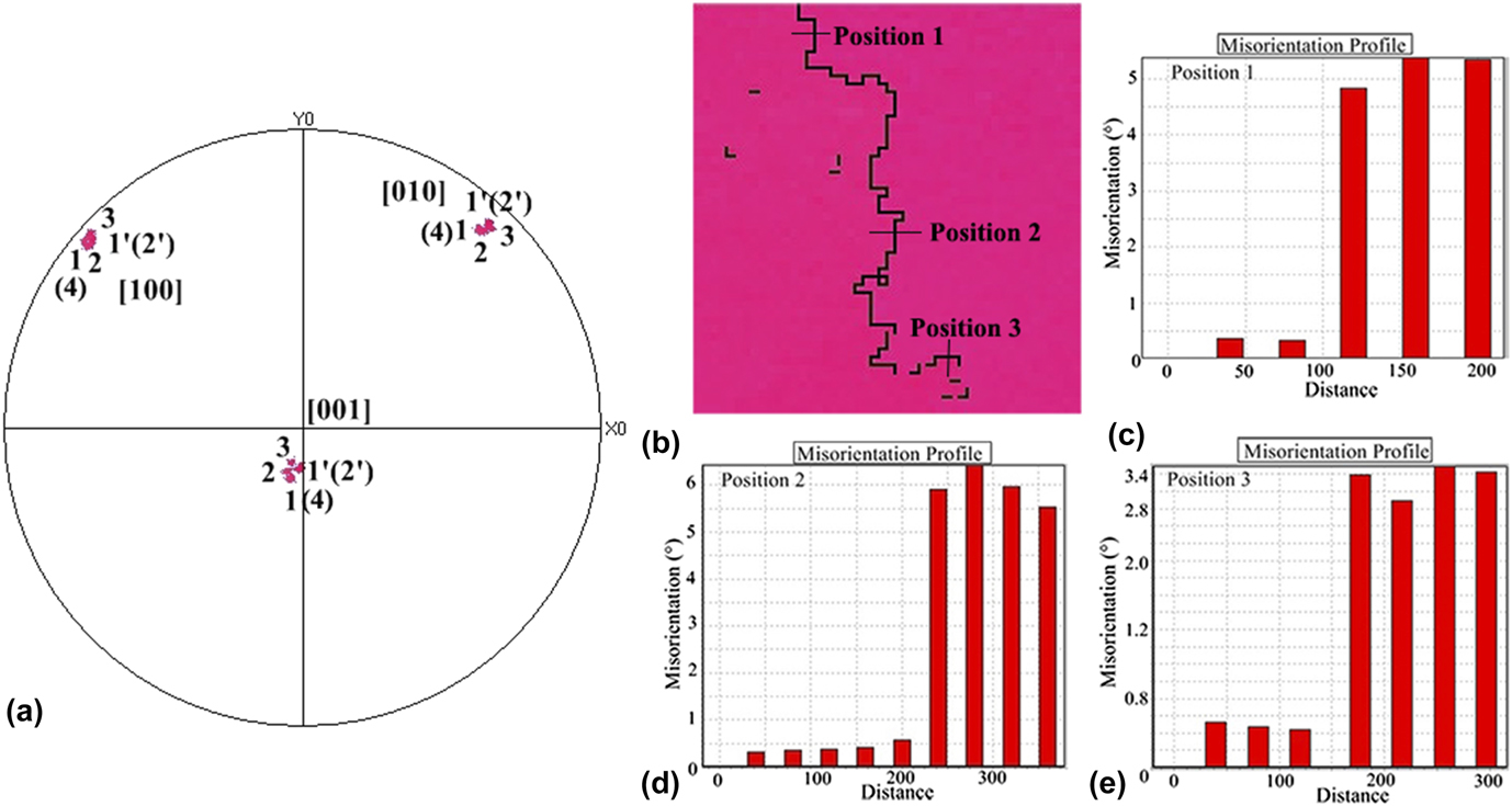
To explore whether there was accumulation of orientation deviation in the dendrite growth process, as mentioned in other studies,Reference Newell, D’Souza and Green11,Reference Newell, Devendra, Jennings and D’Souza16,Reference Newell, D’Souza and Green17,Reference Miller and Pollock32,Reference Zhang, Zhou, Han, Jin and Sun34 the dendrite orientations of six different regions of the rejoined platforms [marked 1, 2, 3, 4, 1′, and 2′ in Fig. 7(a)] were measured by EBSD. Figure 9(a) exhibits the corresponding polar diagrams of the six positions. It can be seen that the six groups had close [010] and [100] positions and slightly varied [001] positions, which indicated that the dendrites underwent slight deformation during the growth. However, there was no obvious accumulation of orientation deviation as the position moves towards region M of the platform, which was different from the experiment results of Newell and Souza.Reference Newell, D’Souza and Green17 Meanwhile, the orientation relationship at the LAB-II was further analyzed; its misorientation profiles are shown in Figs. 9(b)–9(e). It can be seen that the GB angles were changing at the different positions. In other words, the orientation of the same group fluctuated during the growth process, which might be caused by the fluctuation of the curvature of the solid–liquid interface in Fig. 8(c). In fact, the higher branches from the same deformed dendrite could form a mosaic and might result in the accumulation of orientation deviation, as mentioned in other studies.Reference Newell, D’Souza and Green11,Reference Newell, Devendra, Jennings and D’Souza16,Reference Miller and Pollock32,Reference Zhang, Zhou, Han, Jin and Sun34 However, the dendrites in region M of test cross section were not derived from the same parent dendrite in the current sample because the solidification rates of dendrites at different positions were different [Fig. 8(d)]. Therefore, the GB was formed when each group of dendrites converged, while no similar accumulation phenomenon was found in the current study.

D. Prevention of different LABs in the rejoined platforms
In the current study, different types of LABs formed in the rejoined platforms, which was related to the growth morphology and orientation evolution of dendrites under different solidification conditions: (i) The first type of longitudinal LABs caused by the original misorientations was common at lower withdrawal rates, especially when the original orientation deviated from the 〈001〉 direction. These LABs were almost unavoidable, because the orientation deviation might be the inherent characteristic of dendrite growth, especially for the castings with large size. It was possible to reduce this type of LABs by minimizing the orientation difference of dendrites in the two independent channels. Thus using the seed method to maintain a strict 〈001〉 orientation might be an effective means. (ii) The second type of longitudinal LABs induced by the slivers might be a case for the dendrites with specific original orientations in the stress concentration region. The formation of this type of LABs might be related to the effect of stress on dendrites in the three-dimensional space, which was a complex physics problem. Therefore, this type has certain contingency, and it was difficult to avoid. Maintaining the consistency between the primary orientation and the casting axis as well as keeping the parallel alignment between the secondary branches and axis of the platforms might be helpful to prevent such defects. (iii) The third type, transverse LABs accompanied by the secondary dendrites of severe lateral growth, was common at a higher withdrawal rate. To reduce this type of LABs, it was necessary to reduce the curvature of the solid–liquid interface by reducing the withdrawal rate or by reducing the lateral heat extraction by assisting the auxiliary facilities. Besides, the grain continuator technique might also be an effective method if the consistency of the original orientation could be guaranteed.
IV. CONCLUSION
The formation of LABs in the rejoined platforms of Ni-based superalloy during directional solidification was explored using both experiment and simulation method. According to the results, some main conclusions are listed as follows:
(1) At lower withdrawal rates, the longitudinal LABs were common in the rejoined platforms because orientation deviations between the dendrites growing in independent channels were inevitable. Fortunately, the angles of these LABs were very small, generally less than 5°, and usually in the tolerance range of the superalloy.
(2) At higher withdrawal rates, the transverse LABs were common in the rejoined platforms, because the secondary branches with severe lateral growth in the middle region of the platforms had complex growth paths and tend to deviate from orientation in the unstable temperature field.
(3) A special type of LABs was accompanied by the sliver defects which were caused by the deformation of secondary dendrites. The deformed dendrites starting at the section extension region could continue to grow into the middle region of the platforms to form sliver defects through competitive growth with their adjacent dendrites.
(4) No accumulation of orientation deviation was found when the dendrites from different parent arms growing at different solidification rates converged with each other.
ACKNOWLEDGMENTS
The authors are grateful for the financial support by the National Natural Science Foundation of China (51331005, 51690163, 51771148, 51631008, and 51501152) and the National Key Research and Development Program (2016YFB0701400 and 2017YFB0702902).