I. INTRODUCTION
Solar-driven steam generation for clean water production has become a hot topic recently since the global water scarcity becomes more severe.Reference Elimelech and Phillip1–Reference Haddeland, Heinke, Biemans, Eisner, FlöRke, Hanasaki, Konzmann, Ludwig, Masaki and Schewe3 The mainly investigated areas include but not limited to water purification,Reference Zhou, Zhuang, He, Tan, Wang and Zhu4–Reference Zhou, Tan, Ji, Zhu, Zhang, Xu, Gan, Yu and Zhu14 water distillation,Reference Tiwari, Singh and Tripathi15–Reference Neumann, Urban, Day, Lal, Nordlander and Halas17 seawater desalination,Reference Zhou, Tan, Wang, Xu, Yuan, Cai, Zhu and Zhu18–Reference Wang, Ou, Wang and Wu23 sterilization,Reference Ishii, Sugavaneshwar, Chen, Dao and Nagao24 degradation of pollutants,Reference Liu, Lou, Ni, Song, Wu, Dasgupta, Tao, Shang and Deng25–Reference Malato, Fernández-Ibáñez, Maldonado, Blanco and Gernjak31 etc. Despite diverse functions for end usage, the main concept is to generate steam by efficiently harvesting solar energy. For this purpose, various kinds of materials and structures have been selected and designed. Regarding the material selection, the mutually accepted principle is to realize nearly perfect absorption of the solar spectrum. As a result, carbon-basedReference Hu, Xu, Zhou, Tan, Wang, Zhu and Zhu5,Reference Ghasemi, Ni, Marconnet, Loomis, Yerci, Miljkovic and Chen8,Reference Neumann, Urban, Day, Lal, Nordlander and Halas17,Reference Li, Lin, Ni, Xu, Hu, Zhu, Lv, Li, Zhu and Zhu21,Reference Wang, He, Cheng, Shi, Liu and Zhu32–Reference Xue, Liu, Chen, Yang, Li, Ding, Duan, Qi and Zhou44 and noble-metal nanoparticles (NPs)Reference Wang, He, Liu, Shi and Zhu9,Reference Zhou, Tan, Ji, Zhu, Zhang, Xu, Gan, Yu and Zhu14,Reference Neumann, Urban, Day, Lal, Nordlander and Halas17,Reference Zhou, Tan, Wang, Xu, Yuan, Cai, Zhu and Zhu18,Reference Liu, Lou, Ni, Song, Wu, Dasgupta, Tao, Shang and Deng25,Reference Guo, Fu, Wang and Wang45–Reference Zhu, Li, Chen, Zhu, Dai, Li, Yang, Yan, Song, Wang, Hitz, Luo, Lu, Yang and Hu54 have been popularly adopted.
In fact, transition-metal nitride NPs (like titanium nitride, or TiN) have been proposed as an alternative, potentially applicable for realizing broadband absorption of the solar-irradiation.Reference Chirumamilla, Chirumamilla, Yang, Roberts, Kristensen, Chaudhuri, Boltasseva, Sutherland, Bozhevolnyi and Pedersen55–Reference Naik, Schroeder, Ni, Kildishev, Sands and Boltasseva57 The interaction between the incoming light and the TiN NPs could excite the localized surface plasmon resonance (LSPR), aka the collective oscillation of electrons. Such a resonance could lead to strongly enhanced heating effect if the energy is dissipated through Landau (nonradiative) dampingReference Gao, Yuan and Gao58 rather than reradiated through light scattering. Previous studies dealing with the numerical absorption of the TiN NPs have demonstrated their broadband and intensified absorption from visible to near infrared bands, which is intrinsically advantageous to the noble metals in terms of absorption bandwidth.Reference Guler, Ndukaife, Naik, Nnanna, Kildishev, Shalaev and Boltasseva59,Reference Naik, Shalaev and Boltasseva60 The Kyoto group has proved that the TiN nanofluid outperforms gold and carbon-black nanofluids in terms of efficiency in solar steam generation experiments.Reference Ishii, Sugavaneshwar and Nagao61 Moreover, the TiN material is refractory, low-cost, biocompatible, chemically stable, and abundant on earth, all of which outperform metals like gold, silver, aluminum, etc.
However, up to now, we have not seen many applications of the TiN to the solar steam generation scheme. Apart from the above-mentioned paper from Kyoto University, the same group has chemically stabilized the TiN NPs on ceramic fiber wool. The hybrid device can work as a steam generator under the irradiation of a sun simulator with the alleged more than 80% photothermal conversion efficiency.Reference Kaur, Ishii, Shinde and Nagao62 However, the device is merged in water and cannot float by itself. Actually, the heat condensation and localization could be further improved to free the full potential of the TiN NPs.
Here, we have fabricated a batch of TiN-based solar steam generation devices by filtering the TiN NPs through anodized alumina membranes (AAMs). The pore sizes of the AAM and the TiN NPs have been carefully designed to realize both efficient water supply and evaporation. The top TiN NPs with broadband light absorption acted as a plasmonic heating layer, which converted the absorbed light to heat efficiently for interfacial water heating, and the AAM acted as the mechanical support layer, guaranteeing the heat isolation and continuous water replenishment. With optimized thickness of the TiN top layer, a solar steam generation efficiency of 87.7% was achieved in this study. The current work proves the capability of the TiN NPs as an alternative photothermal material.
II. EXPERIMENTAL
A. Materials characterization
The absorbance of the TiN nanofluids was recorded by using a Lambda 950 Vis/NIR spectrophotometer (PerkinElmer, Waltham, Massachusetts). The spectrum is normalized to deionized (DI) water. The crystallinity of the TiN NPs was characterized by X-ray diffraction (XRD, Rigaku D/MAX-UltimaIII, Tokyo, Japan). The morphologies of the AAM and TiN-AAM devices were characterized by using a field emission scanning electron microscope (FESEM, JEOL JSM-7000F, Tokyo, Japan).
B. Fabrication of the hybrid TiN-AAM solar steam generators
The AAM (diameter: 1.5 cm, pores of 20-nm diameter on the top surface) was immersed in hydrogen peroxide (30 wt%) overnight at room temperature to obtain the OH group. Hydroxyl (OH) groups on the AAM surface helped to form hydrogen bonds between the water and the bottom surface of the AAM, making it hydrophilic. TiN powders with an average grain size of 40 nm, synthesized through plasma processing, were vacuum filtrated on the nanoporous AAM.
C. Solar steam measurement
The TiN-AAM device floated on the surface of a 10 mL beaker full of DI water, which was placed into a hollow container made of polystyrene foam for thermal isolation. A solar simulator (CEL-S500) equipped with an AM1.5 filter for the standard air mass 1.5-G spectrum was used as the illumination source. A double-lens system was used for higher illumination intensity. Once the light was projected on the surface of the sample, the weight change of the evaporation system was recorded by using a 4-decimal electronic precision analytical balance (CP214). The illumination intensity was calibrated with a light intensity meter (air cool thermopile sensor with a 10-mm-diameter detector, CEL-NP2000). An infrared camera (UTi160b, Guangdong, China) was used to capture the temperature files and was calibrated using thermocouples. The measurement uncertainty of the calibrated IR camera was about 1.0 °C. All experiments were typically conducted at an ambient temperature of 16 °C and humidity of ∼43%.
III. RESULTS AND DISCUSSION
A. Photothermal conversion efficiency of TiN NPs: numerical and experimental
Physically, when the light interacts with the metal NPs, the LSPR could be excited. At resonance, both scattering and absorption could be enhanced by the NPs, forming two paths for the decay of the collectively oscillated electrons.Reference Jaque, Martinez Maestro, del Rosal, Haro-Gonzalez, Benayas, Plaza, Martin Rodriguez and Garcia Sole63 The heat induced from the LSPR actually originates from the enhanced absorption of light, whereas the scattering does not contribute directly to thermal energy. Here, we have done a simulation based on the Mie scattering theoryReference Mie64 to evaluate the extinction behaviors for the TiN NPs with different sizes.
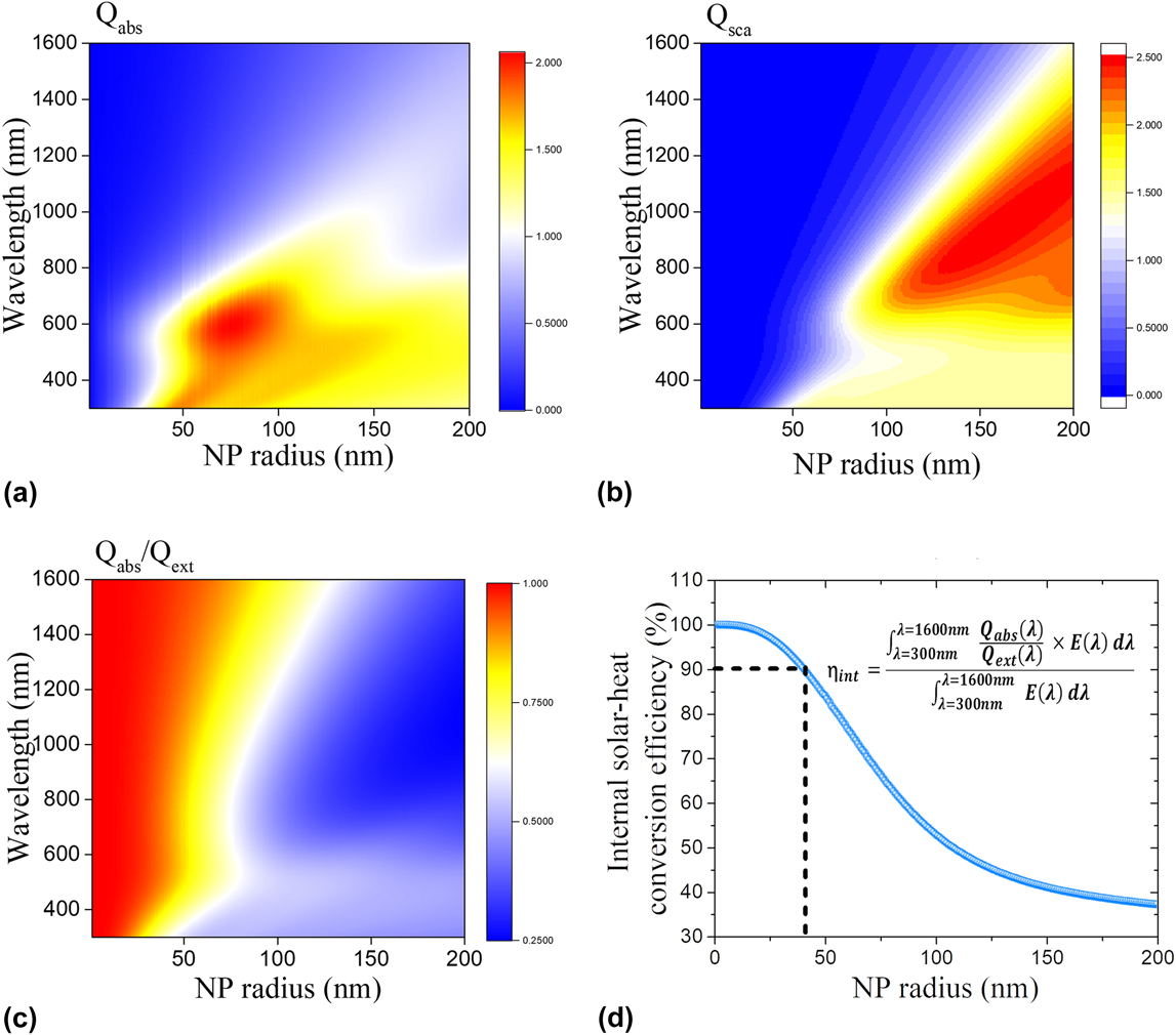
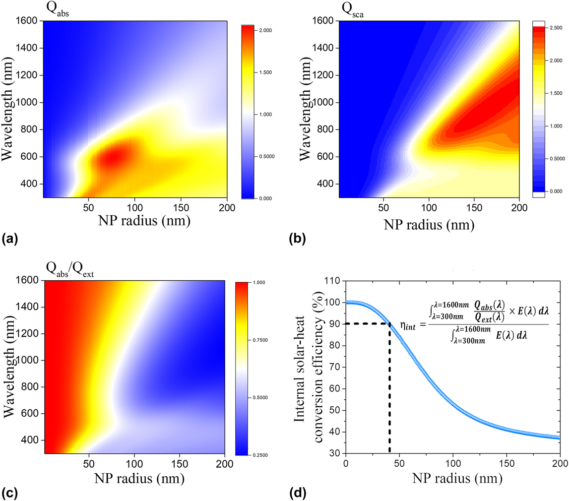
Figures. 1(a) and 1(b) plot the results where the absorption and scattering efficiencies (Q abs and Q sca) are defined by the calculated absorption/scattering cross sections (C abs and C sca) over the geometrical ones of the NPs (Q abs = C abs/πr 2 and Q sca = C sca/πr 2, where r is the radius of the NP). See details of the simulation in the Supplementary Material. The internal photothermal conversion efficiency ηint has been defined by multiplying  ${{{Q_{{\rm{abs}}}}\left( \lambda \right)} \over {{Q_{{\rm{ext}}}}\left( \lambda \right)}}$ [as shown in Fig. 1(c)] and AM 1.5G (E(λ)), and integrating over the wavelength range from 300 to 1600 nm,
 $${\eta _{{\mathop{\rm int}} }} = {{\int_{\lambda = 300{\rm{nm}}}^{\lambda = 1600{\rm{nm}}} {{{{Q_{{\rm{abs}}}}\left( \lambda \right)} \over {{Q_{{\rm{ext}}}}\left( \lambda \right)}}} \times E\left( \lambda \right){\rm{d}}\lambda } \over {\int_{\lambda = 300{\rm{nm}}}^{\lambda = 1600{\rm{nm}}} {E\left( \lambda \right){\rm{d}}\lambda } }}\quad ,$$
where the Q ext(λ) = Q abs(λ) + Q sca(λ), meaning the total extinction. The ηint as a function of the particle radius has been plotted in Fig. 1(d). As can be seen from Figs. 1(a) and 1(b), the absorption/scattering depends on the particle size and the wavelength of incidence. Generally, for smaller particles, the absorption efficiency is higher at shorter wavelength and, while for larger ones, the scattering efficiency is higher at longer wavelength. As can be seen from the Fig. 1(d), the TiN nanosphere smaller than 80 nm in diameter owns high internal photothermal conversion efficiency (>90%). Although the absorption efficiency for the smaller particles is slightly lower as shown in Fig. 1(a), when applying the NPs to actual heating devices, the broadband absorption is commonly achieved by assembling the NPs with different sizes and shapes intentionallyReference Khlebtsov, Zharov, Melnikov, Tuchin and Khlebtsov65,Reference Chen, Shao, Ming, Sun, Zhao, Yang and Wang66 or unintentionally.Reference Bae, Kang, Cho, Park, Kim and Padilla13,Reference Zhou, Tan, Ji, Zhu, Zhang, Xu, Gan, Yu and Zhu14,Reference Zhou, Tan, Wang, Xu, Yuan, Cai, Zhu and Zhu18 It is known that as increasing the size or elongating the spherical particle to an elliptic shape, the LSPR peak will red shift.Reference Chen, Shao, Ming, Sun, Zhao, Yang and Wang66–Reference Njoki, Lim, Mott, Park, Khan, Mishra, Sujakumar, Luo and Zhong69 Therefore, a full-spectrum absorption could be realized statistically with legions of NPs with diverse shape and size. Meanwhile, the scattered light decayed from the LSPR could be reabsorbed by the NPs. In this case, much closer packing of the NPs could enhance the rate of the reabsorption process and further the photothermal conversion efficiency.
Theoretical analysis of the absorption, scattering, and the photothermal conversion efficiency of TiN NPs. The absorption efficiency Q abs (a) and scattering efficiency Q sca (b) of TiN spherical NPs in air having different radii obtained from Mie calculation. (c) The contour plot of absorption/extinction of TiN spherical NPs in air as a function of radius and wavelength. (d) Theoretical internal photothermal conversion efficiency as a function of TiN nanosphere radius. For TiN nanosphere with the radius <40 nm, a >90% of internal solar-heat conversion efficiency could be achieved.
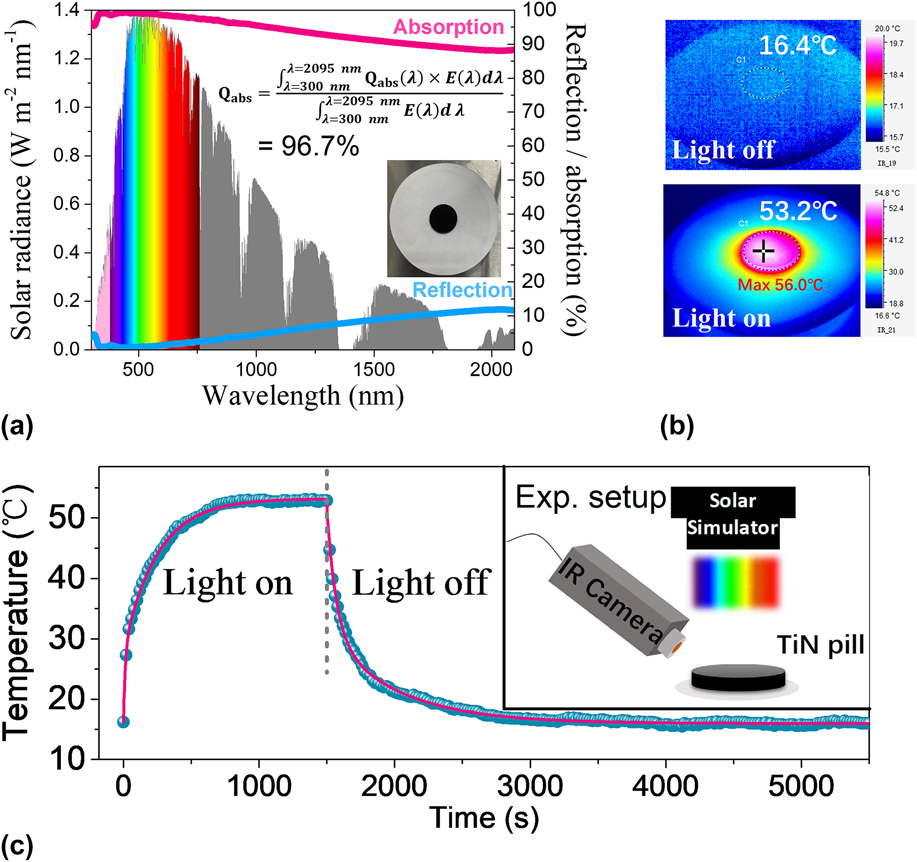
With this idea, we have fabricated a round pill comprised of closely packed TiN NPs with the average diameter of 40–50 nm, which is optimized for the maximum overlapping with the solar spectrum as well as the relatively high internal photothermal conversion efficiency. XRD patterns show that TiN NPs are of the face-centered cubic structure. (Supplementary Material) The fabrication process is by pressing hard on the NPs, guaranteeing the dense packing of the NPs. The reflectance spectrum for this TiN pill shown in Fig. 2(a) indicates that reflectance, R, is less than 10% in a broad spectral range from 300 to 2500 nm. Given no transmission contribution, the absorption spectrum is derived simply as (1 − R). By weighing the absorption spectrum to the solar spectrum at each wavelength, extra high absorption efficiency is achieved up to 96.7%. The perfect absorbance is partially ascribed to the agglomeration of small NPs which is evidenced by the dynamical light scattering characterizations. (Supplementary Material) The average size of the NPs has been estimated at around 52 nm which is larger than the size of the NPs used. The effective size of the NPs distributes from 40 to 100 nm or so, leading to a broadened absorption as compared to a single NP. Besides, the reabsorption of the scattered photons within the densely packed bulk will further increase the absorption.
Absorption and photothermal property of TiN NPs. (a) The solar spectral irradiance (AM 1.5G) (left-hand side axis), and the reflection and absorption (right-hand side axis) spectra of the TiN pill. (b) Infrared images of the TiN pill when the sun simulator is off (the upper panel) and is on for a duration of 15 min (the lower panel). (c) The temperature dependence on time during light on and light off. The inset is a schematic of the measurement setup.
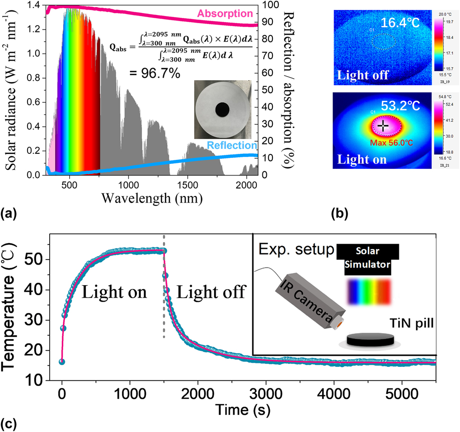
The photothermal conversion efficiency for the TiN pill has been evaluated as shown in Figs. 2(b) and 2(c). The experimental setup has been illustrated in the inset of Fig. 2(c) where a sun simulator (AM 1.5G) is placed on top of the TiN pill. Figure 2(c) shows the temperature profiles of the TiN pill. With the irradiation flux of 0.75 kW/m2, the TiN pill could be heated to 53.2 °C within 15 min as shown in Fig. 2(b). Taking the similar photocalorimetric method,Reference Wang, Li, Deng, Wei, Weng, Dong, Qi, Qiu, Chen and Wu70 [details in the Supplementary Material], the external photothermal conversion efficiency (ηext), defined as the ratio of the generated heat over the irradiation energy, is extracted to be as 94.8%. Considering that 96.7% of solar irradiation can be absorbed, the TiN round pill could transfer ∼98% of the absorbed photon energy into thermal energy, well accordance with the theoretical calculated ηint. Wang et al. have recently reported such a nearly 100% internal photothermal conversion efficiency for a novel narrow-band material Ti2O3.Reference Wang, Li, Deng, Wei, Weng, Dong, Qi, Qiu, Chen and Wu70 In comparison, TiN owns a slightly higher ηext owing to the higher light absorption capability [TiN (96.7%) and Ti2O3 (92.5%)]. The thermal stability for the TiN NP is quite stable. Even under strong oxidizing ambience, the TiN phase can be stable up to 400 °C. [See details for the annealing experiments in the Supplementary Material.] It can be concluded that TiN NPs can be a desirable solar-heating material which can be implemented into the high efficiency solar steam generation.
B. Solar steam generation from TiN nanofluid
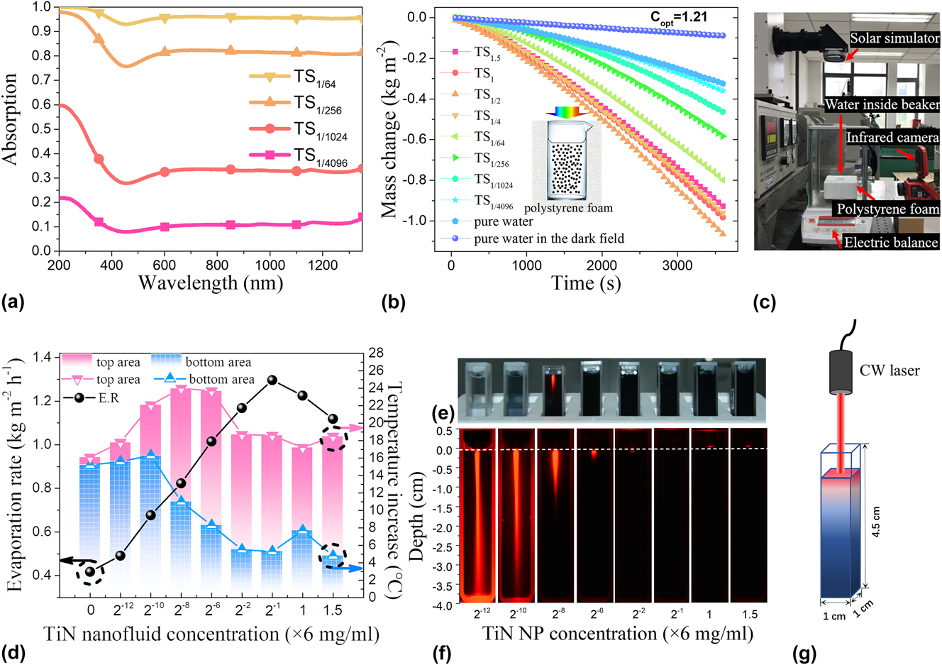
As an instant example, we shall first evaluate the solar steam generation ability of the TiN nanofluid. TiN NP solutions with the concentrations of 9 mg/mL and 6 mg/mL have been prepared, and the latter has been further diluted by a factor of 2, 4, 64, 256, 1024, 4096 for later use (hereinafter labeled as TS1.5, TS1, TS1/2, TS1/4, TS1/64, TS1/256, TS1/1024, and TS1/4096, respectively, for sample identification). As can be seen from photographs in Fig. 3(d), the solution becomes less transparent as increasing the amount of the TiN NPs. Figure 3(a) shows the absorption spectra for some of the representative nanofluid samples. It could be easily understood that the absorbance increases as increasing the amount of the TiN NPs in solution. When the amount reaches 0.09 mg/mL, the averaged absorbance of over 90% could be achieved. The broad absorption band from 450 nm to 1400 nm is a result of the LSPR. It is intriguing to note that the shape of the absorption spectra is different to that of the TiN pill, as shown in Fig. 2(a), but resemble those of the loosely distributed TiN NPs.Reference Ishii, Sugavaneshwar and Nagao61,Reference Kaur, Ishii, Shinde and Nagao62,Reference Guler, Kildishev, Boltasseva and Shalaev71 This result may indicate that the TiN NPs have been dispersed homogeneously and separately in water, and the clustering level of the NPs should be lower compared to that for the round pill. Therefore, the loss due to scattering could be enhanced, which results in a slight drop of the absorbance at the near infrared region.
TiN nanofluid-based solar steam generation. (a) UV-vis-NIR absorption spectra of TiN nanofluids with different mass concentrations. Note that absorbance contains scattered light in addition to absorbed light. (b) The mass change of water and TiN nanofluids with different mass concentrations as a function of irradiation time. The inset is a schematic of the setup. (c) Optical photo of the experimental setup for the water evaporation performance measurement. (d) Evaporation rate (E.R., left-hand side axis), and the temperatures measured at the top and bottom areas (right-hand side axis) of the plasmonic nanofluids with different TiN concentrations at an illumination duration of 3600 s. (e) Photographs of TiN nanofluids at different concentrations. The third cuvette (from left to right) shows Tyndall scattering effect in the NP solution with a CW red laser (640 nm wavelength) incident from the top. (f) Experimental images of the scattered light as viewed through the side faces of the cuvette containing TiN NPs of the indicated concentrations. Exposure times are kept the same for all experiments. (g) Schematic illustration of the multiparticle optical interactions observation setup. The dimension of the cuvette is 1 cm (L) by 1 cm (W) by 4.5 cm (H).
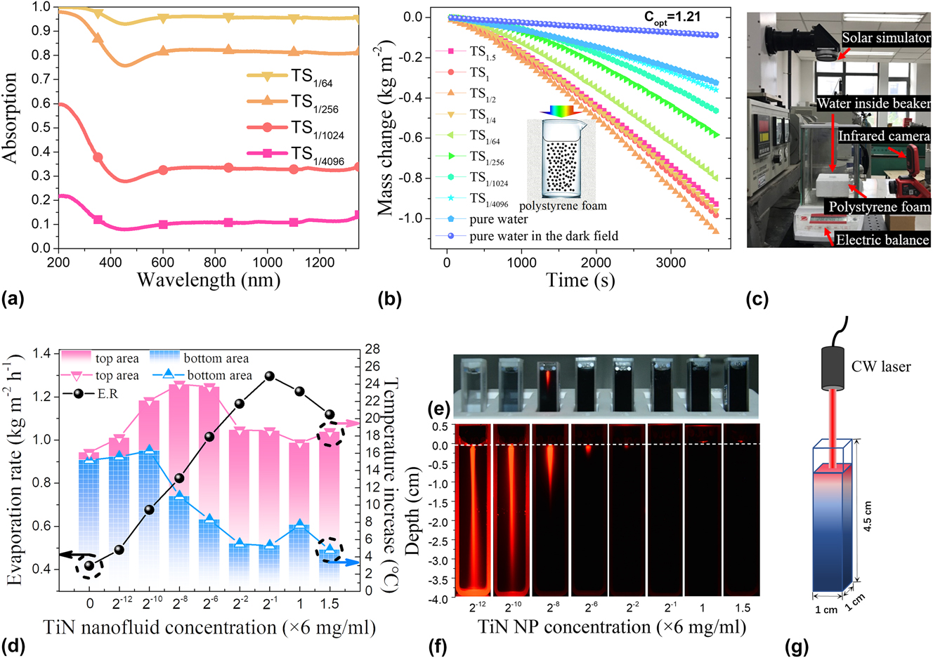
The steam generation experiments have been carried out by placing the beakers containing different amounts of TiN NPs on an electronic balance. The sun simulator irradiates on the exact top of the beakers. The experimental setup is shown in Fig. 3(c). The mass change has been plotted in Fig. 3(b). It is evident that the steam generation with the TiN nanofluid is much more efficient than pure water under the same optical concentration condition. The evaporation rate has been derived from Fig. 3(b) by extracting the slope of the weight loss curves once the evaporation rate reaches the steady state, as shown in Fig. 3(d). For pure water, despite the small absorption in the visible range, the larger absorption in the infrared regime leads to the enhanced evaporation rate (∼4.7 times) compared with a dark environment [The ‘dark’ evaporation rate for pure water is 88 mg/(m2 h)]. For the nanofluid, generally, the higher the concentration is, the faster the water vaporizes due to the enhanced absorption of the irradiation. Meanwhile, the shortened path length of the incident light of solutions for the higher-concentration nanofluids leads to localized light absorption and heat generation within a small portion of bulk water and further the increased water evaporation.Reference Hogan, Urban, Ayala-Orozco, Pimpinelli, Nordlander and Halas72 However, the over-concentrated TiN nanofluid (concentrations higher than 6 mg/mL) results in a slight decrease of the evaporation rate. We speculate that adding excessive amount of TiN NP into water is not easy to form homogeneous suspension where the top part of the nanofluid contains less NPs, leading to slower evaporation. Experimentally, increased backscattering off the fluid surface has been observed as shown in Fig. 3(f). That is why the evaporation rates are basically proportional to the TiN nanofluid concentration up to certain concentration and there is an optimal concentration to maximize the evaporation rates.
The temperatures of the nanofluids at the water/air interface and bottom of the beaker have been extracted via a thermocouple and plotted in Fig. 3(d). Generally, the more the NPs, the higher the temperature increases, resulting from the accumulative effect and Coulomb interaction among the individual NPs.Reference Govorov and Richardson73 For the nanofluid with relatively small NP amount, the temperature difference between the top and bottom parts of the nanofluid is not obvious, which is due to the light irradiation going through the entire solution. As increasing the NP amount, the top temperature increases while the bottom temperature decreases because the light penetration depth becomes less and the NPs within the top part of the solution become denser. Further increase of the NP amount results in enhanced evaporation rate where more heat dissipates, leading to the decrease of both the top and bottom temperatures. After the inflection of the evaporation rate, a further decrease of the temperature for the top part and a slight increase of the temperature for the bottom part are consistent with the above speculation that the top part of the solution becomes diluted while the bottom part becomes denser when the TiN NPs are over-dispersed.
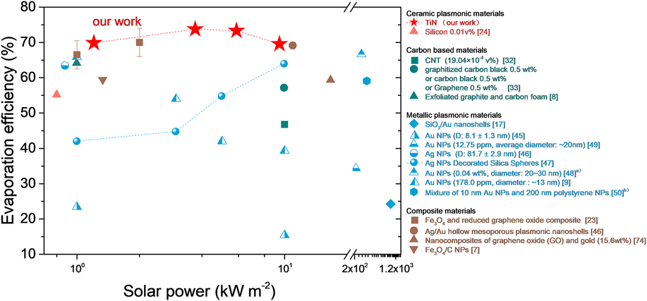
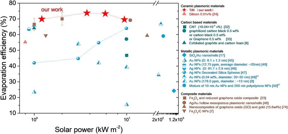
Utilizing the well-established equation in literature studies,Reference Ni, Miljkovic, Ghasemi, Huang, Boriskina, Lin, Wang, Xu, Rahman, Zhang and Chen33 the highest solar-to-steam efficiency of 69.7% has been calculated for the nanofluid sample with the concentration of 3 mg/mL [See details in the Supplementary Material for the calculation of solar-to-steam efficiency]. The Kyoto group did not estimated the efficiency for their TiN nanofluid samples,Reference Ishii, Sugavaneshwar and Nagao61 so this work is the first evaluation of the solar-to-heat efficiency for the optimized TiN nanofluid. Since the efficiency for the nanofluid is without any extra structural designs, it could be a benchmark to evaluate the solar-heating ability for the materials. Figure 4 thus shows the efficiencies for nanofluids made of other kinds of “black” materials from previous literature studies.Reference Ghasemi, Ni, Marconnet, Loomis, Yerci, Miljkovic and Chen8,Reference Wang, He, Liu, Shi and Zhu9,Reference Wang, Ou, Wang and Wu23,Reference Ishii, Sugavaneshwar, Chen, Dao and Nagao24,Reference Wang, He, Cheng, Shi, Liu and Zhu32,Reference Guo, Fu, Wang and Wang45–Reference Zhao, Duan, Yu, Zhang, He, Quan, Tao, Shang, Wu, Song and Deng50,Reference Fu, Mei, Wang, Guo, Dai, Wang, Wang, Li and Wang74 Only the reported optimization results (if existing) are shown for comparison. As can be seen, the efficiency for TiN is comparable to that of some composite materials (brown dots in Fig. 4),Reference Zielinski, Choi, La Grange, Modestino, Hashemi, Pu, Birkhold, Hubbell and Psaltis6,Reference Wang, Ou, Wang and Wu23 and even higher than those of AuReference Wang, He, Liu, Shi and Zhu9,Reference Guo, Fu, Wang and Wang45,Reference Amjad, Raza, Xin, Pervaiz, Xu, Du and Wen48,Reference Jin, Lin, Bai, Zeiny and Wen49 and AgReference Wang, Miao and Tanemura46,Reference Rahman, Younes, Ni, Lu, Raza, Zhang, Fang and Ghaferi47 (cyan dots in Fig. 4), proving that the TiN nanomaterial is excellent for thermal-heating applications. Considering the simpler structure than composite materials, better stability of ceramic-based fluids than carbon-based fluidsReference Ma, Banerjee and Balasubramanian75 and higher evaporation efficiency and more corrosion resistant than widely studied noble metallic plasmonic materials, TiN should be among the prior choices for solar steam generation.
Evaporation efficiency of various suspended particles. Only the reported optimization results (if it exists) are shown for comparison. (a) The calculated efficiency includes the sensible heat. (b) A 532 nm laser was used as the irradiate source.
C. Design, fabrication, and evaluation of the hybrid TiN-AAM solar steam generators
As mentioned above, the merge of the TiN NPs in water is not the most efficient way for the steam-generation process. Visionally in the nanofluid case, under continued illumination, the hot NP enveloped in the nanobubble (a thin layer of steam) travels to the liquid–air interface to release steam, in which case, the heat loss from the travelling nanobubbles to the bulk water is intrinsically unavoidable, limiting the evaporation efficiency. Actually, high-efficient solar steam generation requires confined heat where the hotspots are strongly localized within a small volume at the liquid–air interface. Meanwhile, the bulk water should be designed to be constantly conveyed to the forefront of the vaporization and quickly evaporated. It would be best if we could separate the heating material with bulk water completely but also provide efficient water replenishment. With this concept, therefore, we have designed the hybrid TiN-AAM devices for solar steam generation. Measurements for evaluating the vaporization of water by sunlight revealed that the TiN-AAM devices had a higher efficiency than the TiN nanofluid.
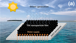
Figure 5(a) shows the schematic of the device, which consists of a layer of TiN NP film on top of the AAM. The NP film has been fabricated by a widely used filtration method.Reference Yu, Zhang, Duan, Liu, Quan, Tao, Shang, Wu, Song and Deng51,Reference Wang, Wang, Song, Megarajan and Jiang76–Reference Guo, Ming, Wang, Hou, Liu, Mei, Li, Wang and Wang80 Such a method is known for its high-speed synthesis of a relatively large area of the uniform NP film with easily tunable composition, microstructure, functionality, and controlled thickness on top of many kinds of porous substrates.Reference Yu, Zhang, Duan, Liu, Quan, Tao, Shang, Wu, Song and Deng51,Reference Wang, Liu, Tao, Shen, Yi, Zhang, Liu, Song, Zhang, Shang and Deng53,Reference Kelf, Sugawara, Cole, Baumberg, Abdelsalam, Cintra, Mahajan, Russell and Bartlett81 The thickness (or channel length) of the AAM used is around 50 μm. AAM with the pore diameter of 20 nm has been selected for the following four reasons: first, noticing that the pore diameter is smaller than the size of the TiN NPs so that it works as the filter during the filtration progress, with the nanochannels not been blocked by the TiN NPs. A densely packed film has been formed on top of the AAM, as shown in Figs. 5(b)–5(e), by the SEM observation. Second, the rich mesostructures of the AAM, as shown in Fig. 5(e), can induce a capillary force, sucking the bottom water up to the liquid–air interface. Considering the height of a liquid column given by Jurin’s law,Reference Batchelor82 a higher height of the liquid column (or better capillary force) could be achieved by reducing the radius of the tube and the water contact angle. So that the mesoporesReference Rouquerol, Avnir, Fairbridge, Everett, Haynes, Pernicone, Ramsay, Sing and Unger83 of the AAM overmatch many other reported hosts with macropores such as wood,Reference Jiang, Liu, Li, Kuang, Xu, Chen, Huang, Jia, Zhao, Hitz, Zhou, Yang, Cui and Hu40–Reference Xue, Liu, Chen, Yang, Li, Ding, Duan, Qi and Zhou44,Reference Zhu, Li, Chen, Zhu, Dai, Li, Yang, Yan, Song, Wang, Hitz, Luo, Lu, Yang and Hu54,Reference Liu, Jiang, Tadepalli, Raliya, Biswas, Naik and Singamaneni84–Reference Jia, Li, Yang, Chen, Yao, Jiang, Kuang, Pastel, Xie, Yang, Das and Hu86 paper,Reference Liu, Yu, Feng, Bernard, Liu, Zhang, Duan, Shang, Tao, Song and Deng52,Reference Fang, Liu, Zhang, Gu, Su, Su, Guo and Zhang87 polyurethane,Reference Wang, Fu, Guo, Mei, Wang, Li and Wang88,Reference Ma, Chiu, Zhu, Tang, Long, Qarony, Zhao, Zhang, Lo and Tsang89 ceramic microfiber wools,Reference Kaur, Ishii, Shinde and Nagao62 silica,Reference Wang, Zhang and Wang39 just to name a few, in terms of water supply. Moreover, we have done a hydrophilic treatment to both sides of the AAM [see details in the Supplementary Material] to strengthen the capillary force for the nanochannels of the AAM. Third, considering the high porosity of the AAM, the effective density of the whole system is smaller than water, making the fabricated TiN-AAM device float on the water surface. Further due to the surface tension, we could ensure that only the lower surface of the AAM contacts water. Such a consideration has been experimentally achieved to prevent the direct contact between the TiN NP film and the water. In this situation, the only path they can get contact with each other is through the nanochannels of the AAM. Additionally, the heat loss to the lower part of the bulk water could be further minimized benefiting from the low thermal conductivity of the AAM.Reference Liu, Lou, Ni, Song, Wu, Dasgupta, Tao, Shang and Deng25
TiN-AAM based solar steam generator. (a) A schematic diagram of the floating solar steam generation device where the AAM is used to support the TiN NPs. (b and c) The top-view (b) and side-view (c) SEM images of the double layered film structure. (d and e) Magnified images of the areas indicated in (c). (f) Optical image of steam generation using TiN-AAM hybrid device under the optical concentration of 6.36 kW/m2.

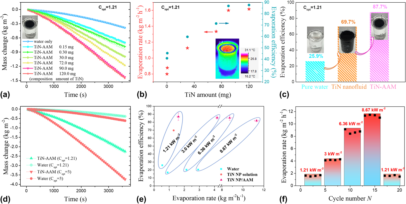
The thickness of the top TiN NP film could be controlled from hundreds of nanometers to millimeters by tuning the volume of the filtrated TiN nanofluid with the same concentration of the TiN NPs [see details in the Supplementary Material]. A batch of sample devices has been fabricated to optimize the thickness of TiN toward water evaporation performance. As expected, visible steam could be generated instantly after the sun simulator is turned on. The mass loss curves and the steam generation efficiency have been recorded, extracted, and shown in Figs. 6(a) and 6(b). The efficiency increases with increasing the volume of the filtered nanofluid which could be easily understood by the increased thickness of the TiN NP film. A further increase of the thickness would lead to a saturation of the efficiency because the light penetration depth should be saturated when continuously increasing the thickness of the absorption layer.
Solar steam generation performance and the durability of the TiN-AAM device. (a) The mass change of water and water with different TiN-AAM devices as a function of the radiation time. The inset shows the floating TiN-AAM device on the water surface. (b) The evaporation rate and corresponding evaporation efficiency of the TiN-AAM device as a function of the amount of TiN NPs. The inset shows the IR camera image of the device with 120 mg TiN filtrated on AAM after 3600 s irradiation with the intensity of 1.21 kW/m2. (c) Efficiency comparison of the pure water, TiN nanofluid (3 mg/mL), and TiN (120 mg)-AAM under 1.21 sun irradiation. The TiN (120 mg)-AAM has a high conversion of 87.7% under 1.21 sun irradiation. (d) Mass change over time with and without the TiN (120 mg)-AAM device under 1.21 and 3 sun irradiation, respectively. (e) The evaporation efficiency of the TiN (120 mg)-AAM device is compared with pure water under 1.21, 3.0, 6.36, 8.67 kW/m2 solar irradiation. The error bars in the evaporation rate and evaporation efficiency are calculated from corresponding experiment results. (f) The evaporation cycle performance of the TiN (120 mg)-AAM device under different optical concentrations.
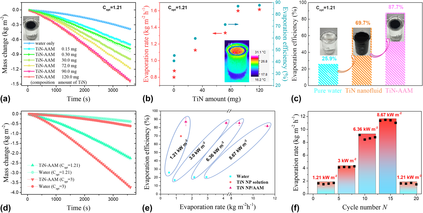
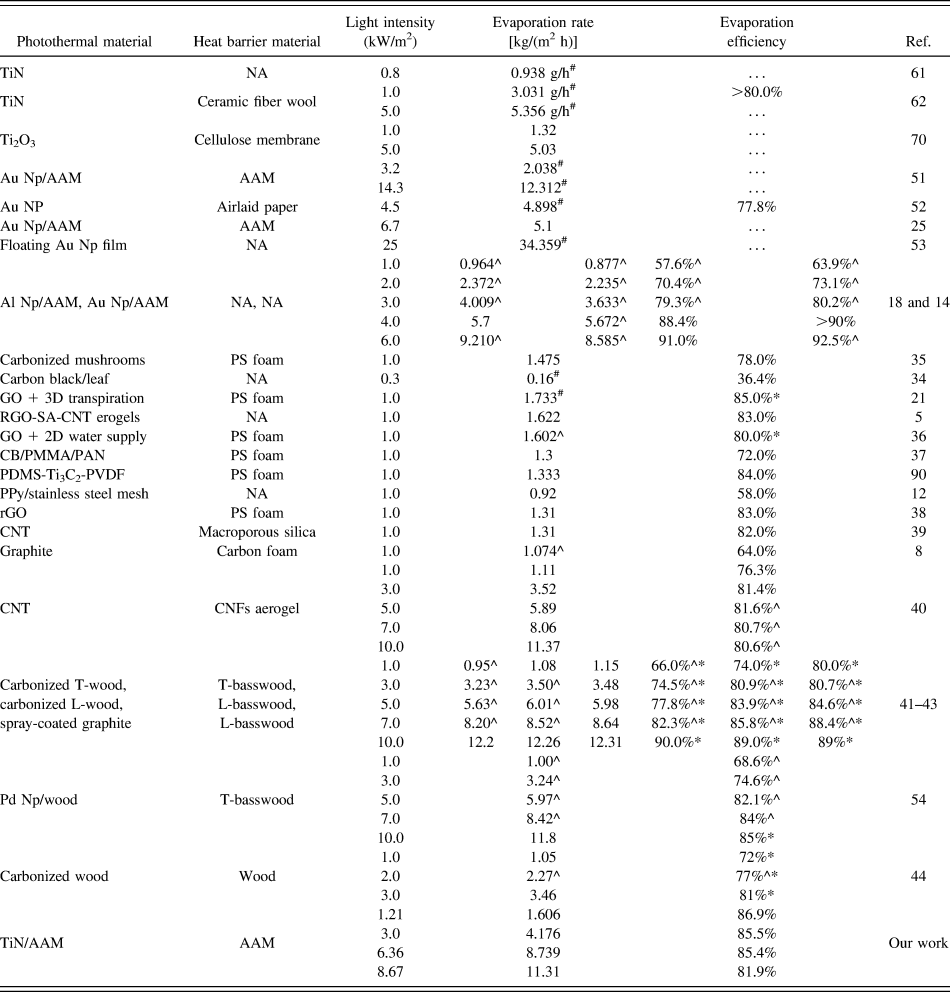
The inset of Fig. 6(b) shows the IR camera image for the device after 3600 s of irradiation with the power of 1.21 kW/m2. The device surface could be heated up to 27.8 °C with 1.21 sun irradiation. A maximum efficiency of 87.7% has been achieved for the device fabricated by filtering 20 mL of the TiN nanofluid (6 mg/mL) [Fig. 6(c), denoted as TiN (120 mg)-AAM device]. Compared with the currently reported designs (Table I), the solar steam efficiency of our device is among the state-of-the-art level.
The solar steam generation performance of various reported structures in the literature studies by different groups.

Hash (#) denotes that the value is calculated from the mass changes in the cited reference. Caret (^) denotes that the value is extracted from figures in the cited reference (rather than reported directly). Asterisk (*) denotes that the calculated efficiency includes the sensible heat. The color of the first column: red represents ceramic plasmonic materials, dark green represents carbon-based materials, light green represents polymer-based materials, yellow represents 2D materials (Ti3C2)Reference Li, Zhang, Shi and Wang90 and blue represents metallic plasmonic materials. The groups summarized above can be distinguished by the color of the last column.
The mass changes with and without the TiN (120 mg)-AAM device over time under different optical concentrations C opt are recorded, as shown in Fig. 6(d). The evaporation rate with the TiN (120 mg)-AAM device for C opt = 3 reaches ∼4.1 kg/(m2 h), which is 4.6 times that of pure water. The evaporation efficiency of the TiN (120 mg)-AAM device is determined under 1.21, 3.0, 6.36, 8.67 kW/m2 solar irradiation on the basis of the extracted evaporation rate [Fig. 6(e)]. This efficiency is compared with pure water at each solar intensity. As shown, the efficiency of pure water stays relatively low (∼20%) in the above irradiation conditions despite the increment of the evaporation rate with the increased solar irradiation, while the TiN-AAM device gives a high performance. A slight reduction of the evaporation efficiency for the TiN-AAM device under 8.67 kW/m2 solar irradiation has been noted, which could be deemed as a result of a deficient water replenishment. In this case, small bubbles could form under the bottom surface of the supporting layer which is also observed in our experiment. However, the reported periodic bubble growth and departure during the whole process of evaporation have not been observed, indicating the key role of the AAM hydrophilization which conveys water to the forefront of the vaporization [see details in the Supplementary Material]. The durability of the device has been also investigated, as shown in Fig. 6(f). The AAM-TiN device shows a stable evaporation rate even after exposing the device under a series of solar irradiance power densities for 20 cycles.
D. Discussion
Such a high efficiency for the solar steam generation should be first ascribed to the TiN nanomaterial. Its strong plasmonic response to a broadband light irradiation is the basis for realizing the excellent heating effect by the decay of the LSPR. Second, the dense TiN NP film is beneficial for the light condensation to achieve nearly perfect light-to-thermal conversion. On the one hand, the dense packing can lead to abundant shapes and sizes for the NPs, which is beneficial for further broadening the absorption bandwidth. On the other hand, the dense packing of the NPs could minimize the light scattering by reabsorbing the scattered light from the decay of the LSPR. The efficiency loss due to scattering is thought to be much less than the configuration for loosely packed or distributed NPs, like chemically bonded on some porous membranes.Reference Zhou, Tan, Ji, Zhu, Zhang, Xu, Gan, Yu and Zhu14,Reference Zhou, Tan, Wang, Xu, Yuan, Cai, Zhu and Zhu18 Third, the hydrophilicity-treated AAM with relatively small pores (20 nm in diameter) can significantly increase the capillary force, making continuous transportation of bulk water to the TiN heating-front. We have actually filtered the TiN nanofluid on some AAM with the pore size of 400–500 nm. Generally, the efficiency is much less for samples having similar TiN film thickness [see details in the Supplementary Material]. The reduced efficiency could be attributed to the following: (i) some of the pores were blocked by the NPs; (ii) the capillary force for larger pores is weaker.
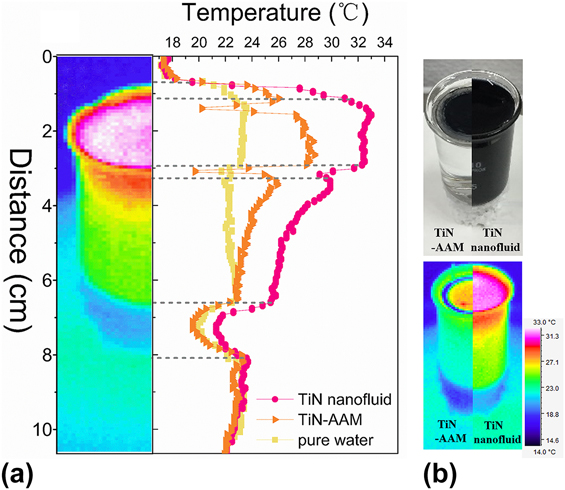
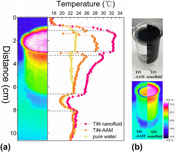
Finally, the well-separation of the functional heating area and bulk water is also a reason for the obtained high efficiency. Different heat behaviors of pure water, TiN-AAM device, and TiN nanofluid have been captured by using an IR camera [see details in the Supplementary Material]. Figure 7 shows the comparison of the temperature distribution in the beakers among water, TiN nanofluid, and the water with the TiN-AAM hybrid device. The IR image has been taken just after 3600 s of irradiation with identical power, which assumes a constant accumulative heating energy from the sun. The cross-sectional temperature distribution parallel to the irradiation direction has also been drawn and shown in Fig. 7(a). The bulk heating nature of pure water is obvious, observing from the uniform temperature increase. Generally, the temperature for the nanofluid and the water with the device is much higher than pure water which demonstrates the absorption-induced heating effect from the TiN NPs. Moreover, it seems strange to find that the temperature for the nanofluid is higher than the water with the TiN-AAM hybrid device for every position. In fact, it is not hard to understand. First, considering the higher evaporation rate for the water with the TiN-AAM hybrid device, more heat has been brought away by the generated vapors. Second, for the nanofluid, much of the absorbed energy has been consumed, heating the bulk water, making the temperature of the bulk water increases as discussed above. This part of energy is actually not utilized for the generation of vapor. In this case, the heating to bulk water could be considered as loss to the purpose of generating vapors. Figure 7(b) puts the two beakers together for a clear comparison. The bulk temperature for the water with the TiN-AAM device is much lower than that for the TiN nanofluid, indicating a significant improvement to the heat localization by using the TiN-AAM device for vapor generation.
Different heating behaviors of pure water, TiN-AAM device, and TiN nanofluid. (a) Temperature profiles of 10 mL beakers with water, TiN (120 mg)-AAM on top of the water surface, and TiN NP solution (3 mg/ml), respectively, after light illumination for 3600 s extracted from the captured IR thermal images. The light illumination intensity is 1.21 kW/m2. Beakers with only a piece of round polystyrene foam on bottom for thermal insulation are used in this experiment. (b) Optical (upper panel) and infrared (lower panel) photos of the beakers with the TiN (120 mg)-AAM device (left half) and the TiN nanofluid (right half). The images are put together for a comparative view.
Reviewing the currently reported vapor generators,Reference Zhou, Tan, Ji, Zhu, Zhang, Xu, Gan, Yu and Zhu14,Reference Zhou, Tan, Wang, Xu, Yuan, Cai, Zhu and Zhu18 the functional material for light absorption is merged under water in some of the designs, which, we think, the efficiency could be further improved by completely isolating the heating area with bulk water. Furthermore, our design and fabrication scheme could be easily transferred to other porous, low-density, low-cost materials, some of which has already been reported, like wood, bionic membranes, cellulous wool, filter paper, green leaves, etc.Reference Zhuang, Zhou, Xu, Xu, Hu, Li, Lv, Zheng, Zhu, Wang and Zhu34,Reference Zhu, Li, Chen, Jiang, Yang, Luo, Wang, Lacey, Dai, Wang, Jia, Wan, Yao, Gong, Yang, Yu, Das and Hu41,Reference Liu, Yu, Feng, Bernard, Liu, Zhang, Duan, Shang, Tao, Song and Deng52,Reference Wang, Li, Deng, Wei, Weng, Dong, Qi, Qiu, Chen and Wu70,Reference Fang, Liu, Zhang, Gu, Su, Su, Guo and Zhang87 We believe that the combination of the low-cost, refractory, plasmonic TiN nanomaterials with some novel supporters would be commercially available for the solar steam generation.
IV. CONCLUSION
In conclusion, TiN NPs have been evaluated for solar-heating application. The photothermal efficiency for the TiN NPs is quite satisfactory as being evaluated by the densely pressed pill and the nanofluid. It has been found that the densely packed TiN NP film can concentrate light with a solar-to-heat efficiency of 94.8%. The TiN NP “pill” has been further assembled onto the AAM with pore size smaller than the average size of the NP by a filtration process. The fabricated TiN-AAM hybrid device can work as a high-efficient solar steam generator with an overall solar-to-vapor efficiency of 87.7%. The isolation between the absorptive material and the bulk water, the packing configuration of the NPs, and the high-efficient water transportation channels have been ascribed to the achieved high-efficiency. The current design concept and the experimental prototype demonstration could be applied to high-efficient water purification, distillation, and desalination applications.
Supplementary Material
To view supplementary material for this article, please visit https://doi.org/10.1557/jmr.2018.326.
ACKNOWLEDGMENTS
This research was supported by the National Natural Science Foundation of China (Nos. 61674077, 61504057, 61574075, and 61774081), the Natural Science Foundation of Jiangsu Province (No. BK20150585), and the Fundamental Research Funds for the Central Universities.