1. INTRODUCTION
Demand for air travel worldwide continues to grow at a rapid rate. For example, between 1990 and 2007, traffic over European airspace not only doubled but also became more complex. Complexity is mainly determined by the number of conflicts which must be detected and resolved to avoid loss of separation between aircraft. Specifically, in 2007, there were 10·1 million civil flights in Europe representing a growth of 5·3% over 2006, thus exceeding the predicted growth of 4·6%. The observed rise in delays and congestion pointed to airspace capacity not matching the rise in demand (EUROCONTROL, 2008). This is expected to get worse since the long term predicted growth in Europe for 2025 is an increase by a factor of between 1·7 and 2·1 over the 2005 level (EUROCONTROL, 2004b). Therefore, there is an urgent need to address the capacity constraints in both the terminal areas and en-route airspace. In response to this, the Single European Sky Air Traffic Management (ATM) Research (SESAR) programme envisages a modernised European ATM system able to accommodate a 73% increase in traffic by 2020, over the 2005 level, whilst meeting targets for safety and quality of service (SESAR Consortium, 2007).
In en-route airspace, capacity is limited by the workload of Air Traffic Controllers (ATCOs). A crucial component of this is the workload required to detect and resolve conflicts (e.g. see Majumdar and Ochieng, Reference Majumdar and Ochieng2002). Hence, a variety of automated decision support tools, ground-based and airborne, are continuously being designed and improved to assist ATCOs, with the added benefit of reducing their workload and increasing airspace capacity. An example of a decision support tool is the user request evaluation tool which includes a conflict probe to continuously check current Flight Plan (FP) trajectories for strategic conflict detection and a trial planning function for ATCOs to evaluate problem resolutions before they are issued as clearances (e.g. see Brudnicki et al., Reference Brudnicki, Lindsay and McFarland1997).
In the future Communications, Navigation and Surveillance/Air Traffic Management (CNS/ATM), DSTs should be able to provide Conflict-Free Trajectories (CFTs) in real time, which must be accurately adhered to by each aircraft to keep separation with the surrounding traffic (EUROCONTROL, 1998). Specifically, two key changes are envisaged for the en-route airspace: the introduction of real time four dimensional (4D) navigation systems and the increasing involvement of the flight crew in maintaining safe separation between aircraft. In the case of the latter, the maximum level of delegation is, for example, proposed in the Free-Flight concept, where the greatest degree of airborne autonomous operations has been recommended (e.g. see Hoekstra, Reference Hoekstra2002). According to this concept, the responsibility for aircraft separation is completely transferred from controllers to pilots, who are then free to choose their preferred routes.
Irrespective of the roles of ATCOs and crew, a number of technical requirements must be met for airborne autonomous operations to become a reality. Firstly, satellite-based 4-D navigation capability must provide the crew with information on their aircraft's current position and that of other proximate aircraft, with high integrity. Secondly, each aircraft must be able to accurately predict its own trajectory over an extended time-horizon (for example, as required for future space based navigation systems enabled procedures) and share such information with surrounding aircraft. Trajectory Predictions (TPs) are then used as input to airborne Conflict Detection and Resolution (CDR) algorithms. Thirdly, using automated communications and digital data links, such as Automatic Dependent Surveillance – Broadcast (ADS-B) systems, each aircraft communicates with both ground controllers and proximate aircraft to negotiate and establish, in real time, conflict-free 4D FPs. It is interesting to note that because of their potential benefits, 4D navigation, TP capabilities and CDR methods are core elements of SESAR (EUROCONTROL, 2007).
1.1. CDR schemes in the open literature
CDR has been an active research topic over the last few years (e.g. see Kuchar and Yang, Reference Kuchar and Yang2000). In particular, Conflict Resolution (CR) algorithms are categorised into three groups according to the methods used to obtain a solution (Hwang et al., Reference Hwang, Kim and Tomlin2007): optimisation, rule-based and force field.
Optimised CR methods produce a resolution manoeuvre which minimises an assigned cost function, such as deviation from the original trajectory, flight time, fuel consumption or energy (e.g. see Dowek et al., Reference Dowek, Munoz and Carreno2005). However, a large computational effort is required, especially when multiple aircraft are involved in the conflict. Although in the future such an effort may be considered routine, these methods are currently not suitable for airborne implementation.
In rule-based CR algorithms, conflict avoidance manoeuvres are fixed and determined according to prescribed rules (e.g. see Bilimoria et al., Reference Bilimoria, Sridhar and Chatterji1996). Such rules are relatively simple and can be easily implemented in an aircraft Flight Management System (FMS). However, unexpected events are not accounted for properly, constituting a threat to safety (Hwang et al., Reference Hwang, Kim and Tomlin2007). Engineered systems designed for the purpose of collision avoidance, such as the Traffic Collision Avoidance System (TCAS), can actually help the crew to deal with unpredicted events. Nevertheless, these safety nets, while being part of the ATM system, are not included in the process of determining the calculated level of safety required for strategic conflict management (e.g. see EUROCONTROL, 2003). For this reason, such tools cannot be considered as an integral part of a strategic system which aims to ensure safe separation between aircraft.
The last class of CR techniques uses force field methods (e.g. see Hoekstra, Reference Hoekstra2001). According to this approach, aircraft are assumed to fly in a force field (jargon from physics) generated by a potential function. Summing over all the repulsive forces of the traffic and the attracting force of the destination is a way to determine a vector, which maintains separation with other aircraft and brings the aircraft to its destination. The resulting resolution manoeuvre is expressed by a relatively simple equation, but may have several discontinuities, leading to situations where aircraft performance limitations may prohibit execution of the requested manoeuvre. Therefore, the effectiveness of the resolution strategy cannot be verified, especially when multiple aircraft manoeuvres are involved in a conflict (Hwang et al., Reference Hwang, Kim and Tomlin2007).
Overall, there are two main limitations of the methods above. Firstly, the actual performance capabilities of a specific aircraft are not considered in the resolution strategy determination processes. This may lead, for example, to a recommended resolution strategy requiring an aircraft to change its altitude with an assigned Rate of Climb or Descent (ROCD) which cannot be obtained given the limitations posed by the aircraft performance capabilities. As a result, the resolution manoeuvre is not executed as required and the proposed resolution strategy becomes unsuccessful. Secondly, while the resolution strategies normally used by ATCOs to safely separate aircraft have been proven over many years, they are not considered explicitly in the existing CDR methods. Clearly, consistency of CDR methods with current ATC procedures is essential if the task of providing safe separation between aircraft is shared between pilots and controllers.
1.2. Factors that influence CDR methods
In general, the performance of any CDR method is driven by essentially three factors: the algorithm used for 4D TP, the communications infrastructure and the resolution strategy.
Accurate 4D TPs are essential for reliable conflict detection. The error margins associated with a predicted trajectory are determined by the algorithm used in the computation process, the quality of input data and the accuracy of underlying models. Specifically, input data include information on the aircraft initial state, which can be derived from both navigation data and airborne instrumentation, while the underlying models deal with aircraft performance parameters and environmental aspects such as wind-field and atmospheric conditions. The input data and parameters associated with both performance and environmental models are usually available with an associated level of uncertainty. If such uncertainties are not considered, an exact knowledge is assumed for both input data and model parameters. Therefore, the outcome of the TP algorithm is a 4D curve, and the aircraft location estimation at a given time is indicated by a point, which coincides with its most probable position. Conversely, if the uncertainties are taken into account and modelled as random variables, the resulting predicted trajectory can be expressed as a 4D tube. In this case, at a given time, the probability density function (PDF) of the aircraft position in space is provided. Such a TP representation is more realistic than a simple 4D curve but requires more computational resources.
It is important that critical data such as TPs are made accessible in real time to all participating aircraft and ATCOs. Hence, suitable communication infrastructure is needed. Specifically, the digital data links' requirements are determined by both the type and amount of information to be communicated. Besides bandwidth requirements, the others include message structure, coding, modulation, and techniques for both interference reduction and packet error detection.
Finally, if a conflict is detected based on aircraft TPs, a resolution manoeuvre must be specified to avoid loss of separation. In general, a given conflict can be solved using alternative strategies, each one with associated benefits and drawbacks. For this reason, the resolution strategy determination process is an essential part of any CDR scheme, as the most suitable manoeuvre must be selected with the aim of maximising safety, in the first place, and then efficiency.
1.3. Paper structure
The main characteristics and assumptions critical to the proposed CDR method are presented in Section 2. Section 3 outlines the 4D TP and aircraft intent models. The CDR method is introduced in Section 4 with particular attention paid to CR in Sections 5 and 6. Numerical results are presented in Section 7, while implementation is dealt with in Section 8. The paper is concluded in Section 9.
2. MAIN CHARACTERISTICS AND GENERAL ASSUMPTIONS
This paper proposes a strategic, pairwise, performance-based and distributed CDR method suitable for airborne implementation.
Strategic, refers to the use of aircraft intent information, defined as a structured set of instructions identifying without any ambiguity how an aircraft is to be operated within a given timeframe (Vilaplana, Reference Vilaplana Ruiz2005). This is essential for accurate TP over an extended time-horizon, thus allowing for accurate and reliable alerting decisions at the conflict detection and CR stages (Kuchar and Yang, Reference Kuchar and Yang2000). Strategic approaches differ from state-based (or tactical) schemes that use only aircraft state information. Although less complex, the former's CDR decisions have a lower level of certainty.
Pairwise denotes the use of CDR logic for two distinct aircraft at a time: the owner and the intruder aircraft. As a result, multiple conflicts, involving more than two aircraft, must be solved sequentially in pairs. In this case, the possibility that one resolution manoeuvre induces a new conflict must be considered and the original solution modified until a conflict-free solution is found. Global approaches may be more robust from this point of view, as the entire traffic situation of a sector under study is examined at the same time. Therefore, the number of additional conflicts induced by a proposed resolution strategy can be minimised. However, compared to pairwise methods, global approaches are more complex and require more computational resources and longer alert time (Kuchar and Yang, Reference Kuchar and Yang2000). For these reasons, they may not be suitable for airborne implementation.
In performance-based methods, aircraft trajectories are predicted taking into account information relevant to aircraft performance. As for the use of aircraft intent, such information allows for an accurate TP over an extended time-horizon and longer term conflict detection. Furthermore, both the effectiveness and the feasibility of the proposed resolution manoeuvres can be verified. As an alternative, if information about aircraft performance is not considered, the TP process can be performed using geometric methods. An example is extrapolating the aircraft position based on its current velocity vector. Although such schemes are relatively straightforward, they are not suitable for a strategic CDR, as accurate predictions can be obtained only within a time-horizon of a few seconds (Kuchar and Yang, Reference Kuchar and Yang2000).
Finally, distributed refers to airborne systems that allow aircraft to detect and solve conflicts on their own, as opposed to centralised systems, where a central unit detects and simultaneously solves the conflicts for all the aircraft. It should be noted that only in distributed systems can the responsibility for decision making progressively move towards the pilots, thereby minimising ATCOs' workload with the potential to increase en-route airspace capacity.
The outcome of the CDR method proposed in this paper is a set of CFTs which must be adhered to by each participating aircraft. The general assumptions made in its development are given below.
2.1. Aircraft protected zone
The proposed CDR method can be applied to a well-defined portion of airspace, i.e. a sector, where the task of ensuring separation with the surrounding aircraft is delegated to both pilots and ATCOs. Flat earth geometry is locally assumed, where position and velocity vectors are given in Cartesian coordinates. This is referred to as the Absolute Reference System (RS) throughout this paper.
Each aircraft is assumed to be at the centre of an imaginary region called the protected zone (e.g. see Kuchar and Yang, Reference Kuchar and Yang2000). A typical three dimensional (3-D) shape of the protected zone is a flat cylinder of diameter D and height H (e.g. see Dowek and Munoz, Reference Dowek and Munoz2007). For example, in accordance with the currently used radar separation minima of 5 nmi horizontally and 1000 ft vertically, D=10 nmi and H=1000 ft can be set. Two aircraft are considered to be in conflict, or in loss of separation, if the protected zone of one aircraft is invaded by another.
Finally, a CFT is a proposed trajectory for an aircraft, which is determined if it enables the associated aircraft to fly through the sector without losing separation with other aircraft. Since the CFT is a prediction, it may become a non-CFT due to an unexpected event. In this case, the CFT computation process must be repeated.
2.2. Priority rule
If a conflict between two or more aircraft is detected, structured resolution manoeuvres must be used to avoid loss of separation. At the same time, the complexity of the proposed solution must be minimised. Coordinating CR efforts is important as it helps to ensure that aircraft do not manoeuvre in directions that could prolong or intensify the detected conflict (e.g. Kuchar and Yang, Reference Kuchar and Yang2000). Furthermore, the manoeuvre must be the simplest possible that fully resolves the conflict and does not introduce additional conflicts with other aircraft. This is essential especially in conflict scenarios involving more than two aircraft.
In the proposed approach for determining CFTs, coordination is achieved using a priority rule, which is a strict priority order of the aircraft (e.g. see Dowek and Munoz, Reference Dowek and Munoz2007). Specifically, if there are N aircraft in the sector, each is allocated an identifier number (ID), i (i=1, 2, …, N), and a priority level, p(i), determined according to a specified algorithm. The lower the priority level, the higher the aircraft priority. For example, if aircraft i has right of way over aircraft j, then the relationship between the priority levels is p(i)<p(j). The priority levels are collected in a N-dimensional “priority vector,” p, whose i-th component is given by p(i). Priority levels can be determined according to different rules. The proposed CDR method requires the resulting priority levels to be unique and time-invariant. Therefore, if an aircraft leaves, or a new aircraft enters a given sector, the priority levels must be redefined and the CFTs re-calculated according to the same set of rules. In this paper, priority levels are, in order of importance, ranked by entry point coordinates, i.e. height and horizontal coordinates, and entry time (Dowek and Munoz, Reference Dowek and Munoz2007).
3. THE 4-D TRAJECTORY PREDICTION MODEL
3.1. High level architecture
An essential aspect of the method proposed is accurate TP over an extended time-horizon. Since accuracy has a cost, in terms of both required input data and system complexity, it is vital that the potential benefits of such predictions are identified. Specifically, accurate TPs are used for reliable, longer term, conflict detection and to verify if a resolution manoeuvre can be executed given the limitations posed by aircraft performance. The TP model used in this paper is developed in Porretta et al. (Reference Porretta, Dupuy, Schuster, Majumdar and Ochieng2008) and makes full use of Expected Times of Arrival (ETAs) at key points on the intended route. A 3D point-mass model for a standard civil aircraft is used to emulate aircraft dynamics, and possible operating modes are captured by a set of discrete variables. The computed trajectory accounts for both aircraft performance and atmospheric conditions. Inputs include navigation data and aircraft intent.
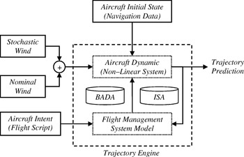
The high level architecture of the TP model is presented in Figure 1 (Porretta et al. Reference Porretta, Dupuy, Schuster, Majumdar and Ochieng2008). The computation process is performed within the Trajectory Engine block, where two systems continuously interact over time. The first is a non-linear control system which captures aircraft dynamics and is characterised by six state variables, four inputs and three disturbances. Three of the six state variables are represented by aircraft coordinates, so the evolution of the state over time provides the TP. The second block models the aircraft FMS. Specifically, it is a control system which, throughout the trajectory computation process, measures the state of the aircraft dynamics and uses this together with aircraft intent information to determine the values of the input variables for the non-linear control system. Aircraft intent is captured in a Flight Script (FS), as described in the next sub-section.
Basic framework for the proposed trajectory prediction model.

Two underlying models are also required by the trajectory engine. The first deals with aircraft performance parameters and is provided by the EUROCONTROL BADA dataset (EUROCONTROL, 2004a). The second copes with atmospheric conditions and is given by the International Standard Atmosphere (ISA) specified by the International Civil Aviation Organisation (ICAO) (ICAO, 1964). In addition to the flight script, which feeds the FMS model, other inputs are needed by the trajectory engine to support the integration of the set of equations which describe the aircraft dynamics. Firstly, the aircraft initial state must be specified using navigational data or airborne instrumentation. Secondly, as the three disturbance variables are given by the three components of the wind speed, a reliable wind-field must be set up. This is a vector field which specifies over time the three components of the wind speed associated to each point of the sector under investigation. According to the scheme recommended in Glover and Lygeros (Reference Glover and Lygeros2003), the wind-field can be evaluated as the sum of two components, nominal and stochastic. The former is derived from wind activity forecasts and/or measurements, while the latter accounts for both uncertainty and spatial correlation properties. It should be noted that further uncertainties are associated with flight script information, aircraft initial state, and aircraft performance parameters. Although these are not considered in the current implementation, their modelling is essential and is currently under study.
According to the proposed approach, the TP problem is closely related to that of an autopilot design problem. For example, assume that, at a certain time, a turn, fly-over or fly-by, is required by the flight script. This happens every time the aircraft must change its heading to move towards the next waypoint. As in an autopilot system, a new set of input variables is then automatically decided by the FMS block, taking into account the actual aircraft state. Finally, the aircraft dynamics block is used to evaluate the effects of these new inputs on the aircraft state, thus updating the predicted trajectory. Furthermore, the four input variables emulate practical control inputs available to the pilot, i.e. engine thrust, bank angle, flight path angle, and drag coefficient. For this reason, their evolution over time provides significant advisories to the crew to efficiently adhere to a conflict-free predicted trajectory.
3.2. Aircraft intent modelling
Aircraft intent information is essential for TP over an extended time-horizon. In the model used for 4D TP (Porretta et al., Reference Porretta, Dupuy, Schuster, Majumdar and Ochieng2008), intent is captured by a flight script, which is expressed as an ordered sequence of Trajectory Change Points (TCPs). TCPs are defined as the points where a significant change in the aircraft state is required. This state takes into account any information useful to characterise aircraft behaviour and includes horizontal position, height, speed, ROCD and heading angle. Particular operating modes, such as flap settings or spoiler configurations for expedited descent, are also considered for an accurate and reliable state identification.
The data related to each TCP are organised in appropriate fields. Besides other indications, relevant to particular operating modes (e.g. turn, holding and expedite descent modes) each TCP identifies where the aircraft should be at a given time, which is specified by an associated ETA. TCPs are then ordered according to the ETA values in the flight script. As a result, any resolution manoeuvres can be effectively expressed in terms of TCPs (Resolution TCPs, RTCPs) and then represented as a subset of aircraft intent instructions.
It is noted that a number of heterogeneous input data types can be summarised in the flight script using TCPs. These include intended routes, airlines' preferences, standard operational procedures and ATCO constraints. In addition, Hazard Zones, No-fly Zones, or regions with severe weather conditions can be avoided by introducing suitable TCPs. During flight, the flight script can be updated in real-time, by adding new TCPs or modifying existing TCPs. Therefore, the RTCPs recommended by a given resolution strategy can be easily integrated in the FS. In addition, the effectiveness of a resolution strategy can be verified promptly by repeating the TP computation process on the basis of the revised flight script. Finally, even unexpected advisories from ATCOs can be considered in the flight script. This is essential to ensure that controllers maintain a supervisory role.
4. THE PROPOSED CONFLICT DETECTION AND RESOLUTION ALGORITHM
The main components of the proposed CDR algorithm are the aircraft coordination mechanism and the CFT computation process.
4.1. Aircraft coordination
It is assumed that, at a given time, there are N aircraft in the sector, and that each aircraft is allocated with an ID, i (i=1,2, …, N), and a priority level, p(i). Each aircraft periodically computes its own TP and, using digital data links, shares this information with all other aircraft. CFT determination efforts are coordinated based on the priority levels. In particular, following the priority order, the proposed CDR scheme is sequentially applied to compute CFTs for all the aircraft, starting with the one with the highest priority. Note that the lower the ranking, the higher the aircraft priority, so that the aircraft whose priority level is 1 is the first to compute its CFT. Once the calculation process is completed, the CFT is broadcast to all the other aircraft. As soon as the CFT relevant to the aircraft with priority level 1 is received, the aircraft with priority level 2 calculates its CFT and, again, transmits it to all the other aircraft. This procedure is repeated for all the aircraft up to the one whose priority level is N.
4.2. Conflict-free trajectory determination for a generic aircraft
In the CFT determination process, each aircraft has the task of avoiding conflicts only with aircraft having a higher priority. This process requires the airborne-computed TP and the TPs relevant to all other aircraft, received through digital data links. As the CFT search is performed sequentially according to the priority order, the TPs received from higher priority aircraft are actually CFTs. In contrast, TPs received from lower priority aircraft are not necessarily conflict-free. The airborne-computed TP is essentially a proposal, which is agreed to become a CFT if, and only if, no conflicts are detected with all the higher priority aircraft.
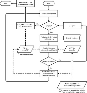
The flowchart of the algorithm underlying the CFT computation process for a generic aircraft, k (k=1,2, …, N), is captured in Figure 2. From Start, a priority index, q, is initialised and set equal to 1. The condition q<p(k) is used to take into account only the aircraft which have priority over aircraft k, i.e. those whose priority levels are 1,2, …, p(k)−2, p(k)−1. If the condition q<p(k) is met, aircraft j, whose priority level is equal to the current priority index, i.e. p(j)=q, is identified. Aircraft j has priority over aircraft k, so it has already evaluated its own CFT. A pairwise CDR algorithm is then applied to detect and solve potential conflicts between aircraft k and j. The algorithm is organised in two separate stages, conflict detection and CR.
The CFT determination process for a generic aircraft, k: square blocks denote processes; diamond blocks indicate decisions; parallelogram blocks specify data which may be modified during the CFT computation procedure; cylinder blocks denote data which are not modified; full line connectors indicate algorithm execution flow; and dashed line connectors specify data flow.

In the conflict detection stage, the airborne-computed TP for aircraft k is used in conjunction with the CFT relevant to aircraft j to determine if the two aircraft are in conflict. If there is no conflict, the priority index, q, is incremented and, provided that q<p(k), another aircraft which has priority over aircraft k is considered. If a potential loss of separation is detected in the conflict detection stage, a pairwise CR scheme is applied. In such a scheme, the resolution task is entirely assigned to the lower priority aircraft, k, and no actions are performed by the higher priority aircraft, j. In other words, only the lower priority aircraft manoeuvres to keep separation with the higher priority aircraft. Aircraft k then acts as an owner, as it takes full responsibility for solving the conflict with aircraft j which, in contrast, acts as an intruder.
The outcome of the CR scheme is an effective resolution strategy for the owner. In particular, TPs and CFTs from other aircraft are used to figure out a strategy which does not introduce additional conflicts. The strategy is summarised in a set of RTCPs which specify where the owner should be at a given time. These RTCPs are then included in the owner FS. Therefore, a new TP can be calculated which incorporates the manoeuvres required to solve the conflict with the intruder. In summary, the CR stage produces a new TP for aircraft k based on a suitable modification of its FS.
Once the CR stage is completed, the priority index, q, is reinitialised to 1. Such a choice is motivated by the need to verify that the resolution strategy used to avoid loss of separation between aircraft j and k does not actually lead to new conflicts with any of the other aircraft. This verification also includes aircraft j itself. Therefore, if aircraft j and k have multiple temporal conflicts, such conflicts will be detected and solved sequentially.
When the condition q<p(k) is no longer met, there is no loss of separation between aircraft k and any other aircraft with a higher priority. Therefore, the CFT for aircraft k can be set equal to its updated TP and broadcast to all other aircraft. After that, the CFT determination process comes to its End (Figure 2). It is emphasised that, in the particular case that aircraft k has the highest priority, i.e. p(k)=1, the condition q<p(k) is never verified, so the CFT for the aircraft exactly matches its unmodified TP.
For traffic evolution monitoring, the CFT computation process is repeated, at regular intervals, for all aircraft in the sector. Note that the higher the traffic in the sector, the shorter the interval. The process is also repeated if other aircraft enter/leave the sector or in case of any unexpected event that requires the re-definition of priority levels.
5. THE CONFLICT RESOLUTION STAGE
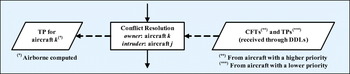
The proposed pairwise CR algorithm is an essential part of the CFT determination process for a generic aircraft, k (Figure 2). As noted earlier, the input data to the CR block include both TPs and CFTs received from lower and higher priority aircraft, respectively. The outcome is a TP for the owner which is inclusive of suitable resolution manoeuvres to keep separation with the considered intruder. This is summarised in Figure 3, which is a particular component of the flowchart in Figure 2.
– CR stage: input and output.

The owner TP is calculated on the basis of an FS which is revised through the possible elimination of existing TCPs and/or the introduction of suitable RTCPs. Specifically, the RTCPs' determination process requires the specification of appropriate resolution parameters. These parameters are discussed below followed by the details of the CR algorithm.
5.1. Resolution Parameters
In the CR algorithm, the RTCPs are determined under the assumption that the owner is able to fly through them following a linear path. However, this assumption may actually not be verified because of a number of factors such as wind-field, aircraft performance parameters, non-instantaneous heading changes, and finite ROCDs. In particular, heading changes cannot be considered instantaneous as aircraft turn radii are not negligible. For example, if an aircraft is flying at a True Air Speed (TAS) of 220 m/s, and the turn is performed with a maximum bank angle of 35°, the turn radius is approximately 7046 m, which is comparable (about 76%) to the radius, D/2=5 nmi=9266 m, of the protected zone.
Because of all the factors which may cause deviation of the actual trajectory from the linear path, proper safety margin must be considered to ensure that the RTCPs are not placed too close to the intruder protected zone. This can be achieved by considering, in the CR stage, a protected zone which is larger than that based on both horizontal and vertical separation requirements. Specifically, the protected zone used in the CR stage is a cylinder with diameter D CR⩾2D and height H CR⩾H. These values are also referred to as resolution parameters, and the choice D CR⩾2D is motivated by the fact that aircraft turn radii may be comparable with the radius of the protected zone, D.
The resolution parameters, D CR and H CR, may be further increased during the CR algorithm. If a resolution strategy is proven to be unsuccessful, the associated RTCPs must be discarded and a new solution found. This can be done by repeating the CR stage with a protected zone which is larger than that previously considered. As a result, a new resolution strategy is obtained which, in general, requires a larger airspace occupation. The mechanism used in this paper to update the resolution parameters is summarised as follows:
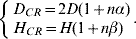
In Equation (1), n is an integer number (resolution index) which is initialised to zero and incremented every time a recommended strategy is shown to be unsuccessful, while α and β are real positive numbers which determine how much, at each iteration, D CR and H CR are increased. The values of the increments α and β must be chosen based upon the following considerations. While small values may determine a new resolution strategy which is not significantly different from the previous one, large values may lead to manoeuvres which require an excessive airspace occupation or are not flyable because of aircraft performance limitations. In this paper, the values α=0·2 and β=0·5 are selected. This results, at each iteration, in an increment for D CR and H CR of 1 nmi and 1000 ft, respectively.
5.2. The pairwise conflict resolution algorithm
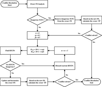
The flowchart of the algorithm is captured in the Figure 4. From Conflict Resolution Start, the first task performed by the algorithm is an analysis of the owner FS to identify possible dangerous TCPs. These are defined as owner TCPs which, at the corresponding ETA, are predicted to be located within the intruder protected zone. If one or more dangerous TCPs are identified, the only action performed by the algorithm at this stage is to remove them from the owner FS – an action that may actually be sufficient to solve the conflict. This is verified by recalculating the owner TP based on the revised FS and by executing a subsequent conflict detection stage with the intruder. If the two aircraft are predicted not to be in any further loss of separation, the Conflict Resolution End is reached (Figure 4) and no further actions are executed.
The pairwise CR algorithm: square blocks denote processes; diamond blocks indicate decisions.

If neither dangerous TCPs are identified nor the removal of existing dangerous TCPs from the owner FS is sufficient to solve the detected conflict, an effective resolution strategy is then proposed by the algorithm. As noted earlier, the strategy is summarised in a set of RTCPs, whose determination process requires appropriate resolution parameters. These parameters are set as in equation (1), with α=0·2, β=0·5 and n=0 for the first iteration.
The RTCP determination process, detailed in the next section, is performed by the Find RTCPs block (Figure 4). The outcome is a set of candidate RTCPs, which must undergo two subsequent verifications.
The first verification deals with the risk that the candidate RTCPs, while being potentially able to avoid loss of separation with the intruder, may generate new conflicts with other aircraft. To minimise a priori the likelihood that such new conflicts are induced, information relevant to both TPs and CFTs received from lower and higher priority aircraft, respectively, is used. If some of the RTCPs are predicted to be, at the associated ETA, within the protected zone of some aircraft, the whole set of candidate RTCPs is considered to be dangerous and discarded. The resolution index is then incremented, the resolution parameters updated, and a new set of candidate RTCPs determined.
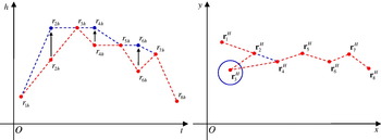
The second verification deals with the effectiveness of the resolution strategy. Provided that the candidate RTCPs are not dangerous, the owner FS is revised to include them. Once the RTCPs are integrated, some modifications are also made to the FS to avoid “unusual” resolution manoeuvres, maintain passenger comfort and minimise fuel consumption. Specifically, “peaks” or “valleys” detected in the vertical profile are eliminated first by adjusting the altitude of the TCP which forms the peak or the valley, or by modifying the altitudes of the adjacent TCPs. Subsequently, possible TCPs which lead the owner back to the sector entry point are also removed from the FS. An example of such modifications, which leads to a harmonised FS for the owner, is represented in Figure 5, where M=8 TCPs are considered. Their positions in the horizontal and the vertical plane are indicated by rmH and r mh (m=1,2, …, M), respectively.
Examples relevant to the FS Harmonisation stage. Vertical profile (right): peaks and valleys are eliminated through suitable modifications for the altitudes associated with TCP2, TCP4 and TCP6. Horizontal profile (left): the TCP3 leads the aircraft back to the sector entry point and is then removed from the FS; the aircraft will fly directly from the TCP2 to the TCP4.

As soon as the owner FS is updated and harmonised, the resolution strategy effectiveness is verified through two steps. Firstly, the owner TP is recalculated based on the new FS, followed by a conflict detection stage with the intruder. If a conflict is detected, a new resolution strategy must be found. Therefore, the current RTCPs are discarded and the resolution index is incremented. The resolution parameters are then updated and a new set of candidate RTCPs found. On the other hand, if no conflict is detected, the Conflict Resolution End is reached (Figure 4) and no further action is required.
In summary, thanks to the resolution parameters update mechanism (Equation (1)), new solutions are constantly generated by the pairwise CR algorithm until an effective resolution strategy is found to solve the detected conflict.
6. THE RESOLUTION TRAJECTORY CHANGE POINTS DETERMINATION PROCESS
The RTCPs determination process is performed by the Find RTCPs block and is part of the pairwise CR algorithm (Figure 4). As noted earlier, input data to such a process include the resolution parameters, D CR and H CR, while the output is a set of candidate RTCPs. Given below are the details of the RTCPs determination algorithm, together with its underlying rationale.
6.1. Underlying Rationale
In the proposed method, candidate RTCPs are set based on the resolution strategies normally invoked by ATCOs in a European airspace, which have been identified in the EUROCONTROL Conflict Resolution Assistant (CORA) project (EUROCONTROL, 2000). Specifically, the hypothetical algorithm outlined in EUROCONTROL (2002), Table 10, page 51, is used to derive recommendations for the RTCPs determination process. This choice allows for the design of a method which is in line with existing ATM systems, whilst preserving operating modes familiar to ATCOs. This is an essential aspect of the proposed method, as ground controllers are assumed, as a minimum, to have a supervision role. The manoeuvres associated with ATCOs' resolution schemes require changes in speed, heading or altitude (or a combination thereof) for the participating aircraft. These recommendations can be effectively captured in terms of RTCPs, which specify where an aircraft should be at a given time.
6.2. Flowchart of the RTCPs determination process
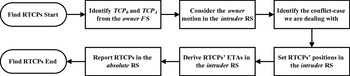
The flowchart of the algorithm executed by the “Find RTCPs” block is presented in Figure 6.
The algorithm consists of a number of steps. After an analysis of the owner FS, the owner motion relative to the intruder is considered. Such a motion is represented in a suitable Reference System (RS) – the intruder RS – where the most appropriate resolution strategy is selected. This strategy is then summarised in a set of RTCPs, whose position and ETAs are first derived in the intruder RS and then reported in the absolute RS. The various steps are described below.
– Flowchart of the RTCPs determination process.

6.2.1. Analysis of the owner flight script
Beginning from Find RTCPs Start, two subsequent TCPs, TCP0 and TCP1, are first identified from the owner FS. Such identification is based on the associated ETAs, τ0 and τ1>τ0, and on the conflict interval [t C, t C+Δt], where t C and Δt indicate the detected time of conflict and the conflict duration, respectively. Specifically, two requirements must be met. Firstly, the associated ETAs must lie, respectively, before and after the conflict duration interval, i.e. τ0<t C and τ1>(t C+Δt); and, secondly, there is no other TCP in the owner FS whose ETA, τ, verifies either τ0<τ<tC or τ1>τ>(t C+Δt). Once TCP0 and TCP1 are identified, two coordinate vectors, r0 and r1, associated with their positions are introduced. The conflict is then solved in the intruder RS, where the owner motion relative to the intruder is represented. Such a reference system is defined in the next subsection.
6.2.2. Representation of the owner motion in the intruder reference system
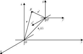
Figure 7 shows the absolute (O, x, y, h) and intruder (O′, x′, y′, h′) reference systems.
Absolute and intruder relative systems.

The origin of the intruder RS coincides with the intruder position and varies over time, while its vertical axis is always oriented as the vertical axis of the absolute RS. The coordinates of a point P, r′, in the intruder RS are related to its coordinates in the absolute RS, r, through the intruder position, in the absolute RS, at an assigned time t, sj(t) as:

The coordinate transformation (2) is time-variant as the specification of the time t is required. For this reason, the vectors r0 and r1 are reported in the intruder RS using the intruder position at the associated ETAs, i.e.: r′0=r0−sj(τ0) and r′1=r1−sj(τ1). Without loss of generality, it is possible to assume hereafter that  and
 with
 ,
 and
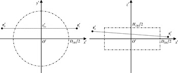
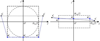
 . Actually, this condition can be obtained through a suitable rotation of the intruder RS around its vertical axis as represented in Figure 8, together with the intruder protected zone used for RTCPs determination. In the intruder RS, such a zone is a cylinder centred at the origin, whose diameter and height are given by the resolution parameters, D CR and H CR, respectively. For RTCPs determination purposes only, the algorithm makes the simplifying assumption that the relative motion of the owner in the intruder RS between the TCPs r′0 and r′1 can be approximated with a straight line. In particular, such an assumption is used to identify the most appropriate resolution strategy, as discussed below.
The protected zone in the intruder RS: Top view (Left) and side view (Right).

6.2.3. Conflict-case identification
As noted earlier, a conflict situation is defined in this paper as a condition where owner and intruder are predicted to be in loss of separation. All the possible conflict situations are categorised according to the resolution strategy used by the owner. A conflict-case is then defined as a set of conflict situations solved by the owner using the same strategy. The rationale underlying the proposed classification scheme is to recognise first conflict situations where a significant change of the owner relative altitude is observed. These situations may actually be the most critical. Specifically, this is done by comparing the relative altitudes  and
 to the height of the protected zone, H. This scheme is presented in Table 1, where all the possible combinations for the values of the relative altitudes are considered. A conflict-case is then unambiguously identified for any conflict situation.
Scheme used for conflict-case identification.

Five possible conflict-cases (A, B, C, D and E in Table 1) are recognised in this paper. Table 1 summarises a complete set of IF statements, e.g. “if  and
 then consider conflict-case E”, etc. Once the conflict-case is determined, an associated resolution strategy is selected by the algorithm and summarised in a suitable set of RTCPs. RTCPs' positions and ETAs are first determined in the intruder RS and then reported in the absolute RS.
6.2.4. Determining the positions of the resolution trajectory change points in the intruder reference system
There is insufficient space to detail the procedure for determining the RTCPs' positions in the intruder RS for all the conflict-cases in Table 1 but the authors can provide full details if required.
For each case, a suitable resolution strategy is proposed and the coordinates of the associated RTCPs provided. Specifically, if M RTCPs are used to summarise the recommended strategy, the outcome of the procedure is a set of M vector coordinates, u′m (m=1,2, …, M), which specify the position of each RTCP in the intruder RS. It is noted that such positions are determined under the assumption that the owner is able to fly through the RTCPs following a linear path (resolution path). This path is formed of M+1 legs and M+2 nodes, as the first and the (M+2)-th nodes are given by TCPs r′0 and r′1, respectively.
An example of the procedure is represented in Figure 9, where a possible strategy to solve a conflict-case D in the intruder RS is indicated. The strategy is summarised using M=3 RTCPs, whose positions in the intruder RS are specified by vectors u′1, u′2 and u′3. The resolution path is then formed of four legs and five nodes (r′0, u′1, u′2, u′3 and r′1) and is represented in Figure 9 by a dashed blue line.
A possible strategy to solve an example of conflict-case D: Top view (Left) and side view (Right).

6.2.5. ETA determination
Once the RTCPs' coordinates, u′m (m=1,2, …, M), are determined in the intruder RS, the associated ETAs, t m, must be set. For this purpose, the overall length of the associated resolution path (r′0, u′1, u′2, …, u′M, r′1) is considered. Such a length is obtained by summing up the lengths of each leg, i.e. L=l 1+l 2+…+l M+l M+1, and is, in general, greater than the distance between TCPs r′0 and r′1. However, in order to meet the ETA requirements, the resolution path must be completed in the same period, Δτ=τ1−τ0, which is available to the owner aircraft to fly directly from r′0 to r′1. By also requiring that each leg of the resolution path is completed in a time which is proportional to the length of the leg, the ETAs t m can be calculated as:

Since the lengths of the legs are all positive, the ETAs determined as in equation (3) are already ordered, i.e. t 1<t 2<…<t M.
6.2.6. Reporting the resolution trajectory change points in the absolute reference system
Once the RTCPs are determined, with the associated ETAs, in the intruder RS, they must be reported in the absolute RS. This is done by considering the inverse transformation of the Equation (2) resulting in (with the same notation and definitions):

The direct, Equation (2), and the inverse, Equation (4), coordinate transformations are both time-variant, as the specification of a time t is required. For this reason, the vectors u′m are reported in the absolute RS using Equation (4) and the intruder position sj(t m) at the associated ETAs, t m, determined at the previous step:

The RTCPs in the absolute RS are eventually given by the set {m=1,2, …, M|um, t m} and their determination process is then completed (Find RTCPs end).
Finally, it is emphasised that the coordinate transformation (5) requires, for each RTCP, the intruder position at the associated ETA. In other words, M samples sj(t m) of the intruder position over time must be considered to determine the position of M RTCPs in the absolute RS. Hence, according to the particular motion of the intruder, an identical set of RTCPs, determined in the intruder RS, may lead to different sets of RTCPs in the absolute RS. In particular, this allows the proposed algorithm to account for the effects of different relative velocities between owner and intruder.
6.3. Discussion
Based on the resolution strategies normally invoked by ATCOs in a European airspace, the recommended RTCPs are designed to prevent the owner from entering the intruder protected zone, while taking into account the owner intended trajectory. For each conflict-case, the solutions presented here are neither unique nor globally optimum, as other parameters such as fuel consumption or airspace occupation are not minimised. As noted earlier, work is in progress to optimise the efficiency of the proposed resolution manoeuvres. A number of different resolution strategies can be suggested using the proposed TCPs' concept and format, making this an open area of research.
7. NUMERICAL RESULTS
The performance of the proposed CDR scheme has been assessed for typical scenarios proposed in the literature, such as super conflict and wall conflict. The scenarios involve more than two aircraft and are characterised by a sequence of conflicts (domino effect), where solving one may trigger a new conflict (e.g. see Hoekstra, Reference Hoekstra2001). In addition, the scenarios have been considered in both the horizontal and vertical planes, in order to cover all possible conflict-cases. The results are presented below, starting with the general assumptions.
7.1. General assumptions
In assessing the performance of the CDR scheme, a uniform and time-invariant wind-field, w=⌊w xw yw k⌋=[15 11 0]m/s, is used, and all aircraft are assumed to be Boeing 737-500 (ICAO Code: B735). However, any other type of aircraft could be considered also, provided that its performance parameters are included in the EUROCONTROL BADA Dataset (EUROCONTROL, 2004a).
It should be noted that in the event of the conflict-case D, two possible solutions are recommended, namely a horizontal and a vertical resolution strategy. (Figure 9 is an example of a horizontal resolution strategy.) In the proposed CR algorithm, one of the two strategies can be set as a preference. If the preferred strategy fails, the algorithm uses the other one to solve the conflict without updating the resolution parameters, i.e. without increasing the resolution index. Only if the second strategy is also unsuccessful are the resolution parameters updated. The two strategies are then repeated in the same order until the conflict is solved.
The numerical results presented in this section have been obtained by preferring a horizontal strategy for both the super conflict and wall conflict scenarios in the horizontal plane, and a vertical strategy for the analogous scenarios in the vertical plane. These preferences have been set to evaluate CDR performance in the presence of domino effects.
7.2. Super conflict in the horizontal plane
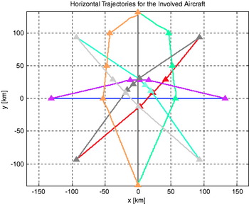
In this scenario, N aircraft are assumed to be, at a certain time, at the same altitude and located on a circumference of a circle of an assigned radius. The circumference is divided by the aircraft initial positions into N arcs of the same length. The aim of each aircraft is to reach the opposite point of the circumference, following a route which is intended to pass through the centre. Furthermore, all the aircraft are assumed to be flying at the same speed.
Numerical results relevant to a super conflict in the horizontal plane with N=8 aircraft are presented in Figure 10, together with the RTCPs used to avoid loss of separation. All the conflicts are shown to be solved using only horizontal resolution manoeuvres. Therefore, only the aircraft horizontal trajectories are presented. As shown in the figure, the blue aircraft has the highest priority. For this reason, no modifications are required to its nominal trajectory. Such a trajectory is defined as the aircraft intended route between the sector entry and exit points, without taking into account possible resolution manoeuvres which must be performed to avoid conflicts with other aircraft. On the other hand, the yellow and the green aircraft have the lowest priorities. As a consequence, they experience the largest deviations from their nominal trajectory. In this case, large values of the resolution parameters are actually needed by the CR algorithm to avoid loss of separation with the other aircraft.
Super conflict in the horizontal plane: Horizontal trajectories.

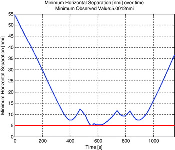
As noted earlier, no significant changes are predicted in this scenario for the aircraft altitudes. Therefore, vertical separations between each couple of aircraft are almost zero all the time. Minimum separation requirements are then met by resorting to adequate horizontal separations. In Figure 11, the minimum horizontal separation over time, d minH(t), is reported. Such a separation is defined as the minimum horizontal separation observed amongst all possible aircraft pairs. As shown in Figure 11, it is always d minH(t)⩾D/2. Therefore, minimum separation requirements are predicted to be met for all the participating aircraft. It is also noted that, although the proposed CR scheme is not optimum in the sense of airspace occupation, the minimum observed value for d minH(t) is, for this scenario, very close to the minimum horizontal separation requirement, D/2.
Super conflict in the horizontal plane: Minimum horizontal separation over time.

It is underlined that super conflict scenarios are very difficult situations to deal with. As a matter of fact, they are sometimes used for training ATCOs (e.g. see Hoekstra, Reference Hoekstra2001). For example, in this case, all the eight aircraft should be managed at the same time by an ATCO. A possible strategy could consist of three steps: (1) request all aircraft to turn right by 90°; (2) wait for confirmation; (3) deal with each aircraft separately. This is clearly a less efficient way to solve this situation (Hoekstra, Reference Hoekstra2001).
7.3. Wall conflict in the horizontal plane
As in the previous scenario, N aircraft are assumed to be, at a certain time, at the same altitude. The first aircraft is assumed to be flying towards the centre of a wall formed by the remaining N-1 aircraft (wall aircraft). These aircraft are placed along a horizontal line perpendicular to the route followed by the first aircraft, with adjacent aircraft at a distance compliant with minimum horizontal separation requirements. The wall aircraft are all assumed to fly parallel, at the same speed, toward the first aircraft.
A trivial solution to the problem posed by the scenario above consists of requesting the first aircraft to change its altitude to avoid the wall. A similar request can be made to the aircraft of the wall which are predicted to be in conflict with the first aircraft. As an alternative, if horizontal manoeuvres are preferred to solve possible conflicts, a sequence of conflicts is triggered and the solution to the problem is not trivial. The trivial solution is the safest because it involves the minimum number of instructions and is the easiest to monitor. Thus, it would be the obvious decision provided by ATCOs. The non-trivial solution is analysed here only to evaluate performance in the presence of the domino effect.
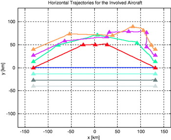
Numerical results relevant to a wall conflict in the horizontal plane with N=8 aircraft are presented in Figure 12, together with the RTCPs used to avoid loss of separation. All conflicts are shown to be solved using only horizontal resolution manoeuvres. Therefore, only the aircraft horizontal trajectories are presented. The first aircraft is represented in blue and is flying from the left to the right in Figure 12. As the first aircraft has the highest priority, no modifications are required to its nominal trajectory. On the contrary, a number of horizontal manoeuvres must be performed by the wall aircraft to avoid conflicts. Specifically, a hole must be created in the centre of the wall through which the first aircraft can fly.
Wall conflict in the horizontal plane: Horizontal trajectories.

In Figure 12, a typical example of a domino effect can be observed. As soon as a conflict is detected with the blue aircraft, the red aircraft, at the centre of the wall, initiates an avoidance manoeuvre and turns to its right. However, owing to such a manoeuvre, the red aircraft loses separation with the green aircraft on its right. Thus, to avoid this new conflict, the green aircraft must also turn to its right, and a further loss of separation is generated with the purple aircraft on its right. The same arguments are repeated for the purple and the yellow aircraft, and a wave of conflicts (domino effect) is then observed through the upper side of the wall. This is a direct consequence of the avoidance manoeuvres required to let the blue aircraft pass through the wall. As shown in Figure 12, multiple conflicts are also detected when the red, green, purple and yellow aircraft perform suitable recovery manoeuvres to merge their nominal trajectories. Because of these conflicts, additional RTCPs are required for the CFTs relevant to the purple and yellow aircraft.
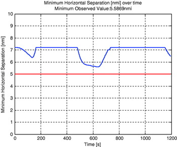
Similarly to the super conflict scenario in the horizontal plane, no significant changes are predicted for the aircraft altitudes. Again, vertical separations between each couple of aircraft are almost zero all the time and minimum separation requirements are met by resorting to adequate horizontal separations only. In Figure 13, the minimum horizontal separation over time, d minH(t), is presented. As shown in the figure, it is always d minH(t)⩾D/2. Therefore, minimum separation requirements are predicted to be met for all participating aircraft. Again, although the proposed CR scheme is not optimum in the sense of airspace occupation, the minimum observed value for d minH(t) is quite close to the minimum horizontal separation requirement, D/2.
Wall conflict in the horizontal plane: Minimum horizontal separation over time.

7.4. Super conflict in the vertical plane
Several conflict-cases identified by the proposed CDR algorithm require a change in the aircraft altitude to avoid loss of separation. However, as actual ROCDs are limited, it is not guaranteed that the recommended resolution path can be effectively adhered to by the aircraft.
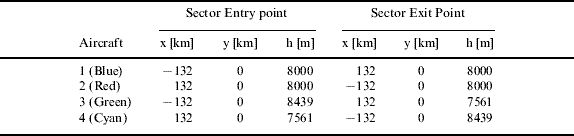
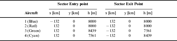
In order to test the proposed CDR scheme in situations where several changes in the aircraft altitude are required, a super conflict scenario in the vertical plane is considered. Specifically, N=4 aircraft are involved. For each aircraft, the coordinates relevant to both the sector entry and exit points are specified in Table 2. Furthermore, the relative ETAs associated with these points are assumed to be τ0=0 s and τ1=1200 s, respectively, for all the aircraft. Finally, it is noted that the four lines joining the entry and the exit points associated with each aircraft intersect at the point of coordinates [x y h]=[0 km 0 km 8000 m].
Super conflict in the vertical plane.
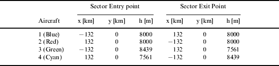
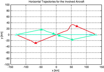
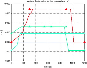
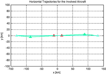
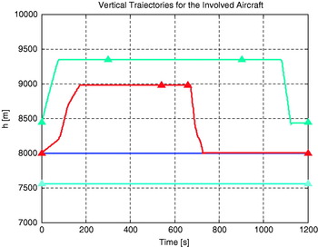
Numerical results are presented in Figures 14 and 15, showing the horizontal and vertical trajectories, respectively, for all participating aircraft.
Super conflict in the vertical plane: Horizontal trajectories.

Super conflict in the vertical plane: Vertical trajectories.

It is observed that both horizontal and vertical resolution manoeuvres are needed to avoid loss of separation. Although all conflicts are successfully solved, some of the proposed resolution paths are only partially adhered to by the aircraft. For example, the predicted vertical trajectories show that the red aircraft is late in reaching the altitude associated with the second TCP, while the green aircraft arrives slightly in advance at the penultimate TCP. These discrepancies between the resolution paths and the associated predicted trajectories are due to a limited ROCD for the red aircraft and to the effects of the wind-field for the green aircraft. For this specific scenario, these inconsistencies do not lead to any conflict, as numerical results show that minimum separation requirements are always met. However, these discrepancies emphasise the importance of verifying the resolution strategies provided by the CR algorithm with an accurate TP model, which takes into account factors such as aircraft performance parameters, non instantaneous turns, limited ROCDs, wind-field and atmospheric conditions.
7.5. Wall conflict in the vertical plane
The wall conflict scenario in the vertical plane is a further situation where several changes in the aircraft altitudes may be required to solve possible conflicts. Specifically, in the performance evaluation presented here, N=4 participating aircraft are considered for this scenario. For each aircraft, the coordinates relevant to both the sector entry and exit points are specified in Table 3. In addition, the relative ETAs associated with these points are assumed to be τ0=0 s and τ1=1200 s, respectively, for all the aircraft.
Super conflict in the vertical plane.
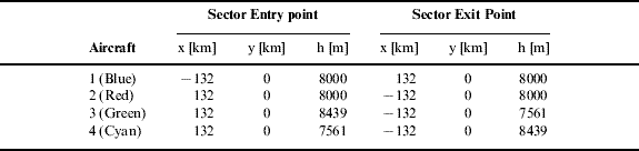
Similar to the wall conflict in the horizontal plane, the blue aircraft is assumed to fly towards the centre of a vertical wall formed by the remaining three aircraft. The wall aircraft are placed along a vertical line which is perpendicular to the route followed by the first aircraft, with adjacent aircraft at a distance compliant with minimum vertical separation requirements. Furthermore, the wall aircraft are all assumed to fly parallel, at the same altitude, toward the first aircraft.
Once more, a trivial solution to the problem posed by this scenario consists in requesting the first aircraft to deviate horizontally to avoid the wall. A similar request could be made to the aircraft of the wall which are predicted to be in conflict with the first aircraft. As for the wall conflict in the horizontal plane scenario, the trivial solution is definitely the safest, because it involves the minimum number of instructions and is the easiest to monitor. Therefore, it would be the obvious decision provided by ATCOs. As an alternative to such a strategy, if vertical manoeuvres are preferred to keep separation, a sequence of conflicts is triggered and the solution to the problem is not trivial. Again, the non-trivial solution is analysed here only to evaluate the performance of the algorithm in the presence of a domino effect.
Numerical results are presented in Figures 16 and 17, showing respectively the horizontal and vertical trajectories for all participating aircraft. With the exception of minor corrections in the horizontal plane for the green aircraft, only vertical resolution manoeuvres are needed to avoid loss of separation. As the first aircraft has the highest priority, no modifications are required to its intended route. However, various vertical manoeuvres must be performed by the wall aircraft to avoid conflicts and create a hole in the centre of the wall through which the first aircraft can fly.
Wall conflict in the vertical plane: Horizontal trajectories.

Wall conflict in the vertical plane: Vertical trajectories.

In analogy with the analogous scenario in the horizontal plane, a small domino effect can be observed in the predicted vertical trajectories. As soon as a conflict is detected with the blue aircraft, the red aircraft, placed at the centre of the wall, initiates a climbing manoeuvre. However, owing to such manoeuvre, the red aircraft loses separation with the green aircraft, which is flying above. Thus, to avoid this new conflict, the green aircraft must also initiate a climbing manoeuvre. Again, a small wave of conflict is observed in the upper side of the wall, as a direct consequence of the avoidance manoeuvres required to let the first aircraft pass through the wall.
As shown in Figure 17, multiple conflicts may be detected when the red and the green aircraft perform suitable descending manoeuvres to merge their nominal trajectories. As for the analogous scenario in the horizontal plane, coordination between aircraft is essential. In this case, the resolution parameters updating mechanism generate RTCPs which ensure that the green aircraft initiates a descending manoeuvre to merge its nominal trajectory only after the red aircraft has descended at an altitude of 8000 m. Again, some of the proposed resolution paths are only partially adhered to by the aircraft. For example, the green aircraft is late in reaching the penultimate RTCP. Once more, for this specific scenario, such discrepancies do not to lead to any conflict, as numerical results show that minimum separation requirements are always met. However, these inconsistencies confirm again that the strategies proposed by the CR algorithm must be validated using an accurate TP model.
8. IMPLEMENTATION ASPECTS
A vital aspect of the method is the approach used to model aircraft intent, which requires a flight script to be set for each participating aircraft. It should be noted that, in general, the specification of a TCP requires more information than that associated with a way point contained in a flight plan as used today. In particular, each TCP of a flight script requires an associated ETA. Another important issue is the quantity of information which must be shared amongst the aircraft using digital data links. As TPs and CFTs are broadcasted, the number of bits of information associated with each prediction can be calculated based on both the sampling rate and the time-horizon. For example, if the time-horizon is 20 min, i.e. 1200 s, and one 4D position estimation sample per second is provided by the TP model, the overall number of samples used to represent the predicted trajectory is 4×(1 sample/s)×1200 s=4800 samples. The factor 4 must be considered as a 4D position estimation sample also has an associated time, i.e. (t x y h). Assuming that 64 bits are used to represent each sample, the overall number of bits of information is eventually calculated as 4800 samples 64 bits/sample=3 07 200 bits=38 400 bytes. This could then be used to specify communication requirements such as bandwidth or to select the most suitable coding technique. Finally, it is underlined that the proposed method is flexible, in the sense that it is suitable for both airborne and ground-based implementations. In particular, the number of technical issues to be addressed is reduced if a ground-based solution is preferred. For example, the amount of information which must be shared between the participating aircraft during the CFT determination process is significantly smaller in this case.
9. CONCLUSIONS
This paper has presented an enhanced strategic, pairwise, performance-based and distributed conflict detection and resolution scheme. Critical to the scheme is an accurate and reliable 4D trajectory prediction model. Such a model uses aircraft intent information and accounts for the effects of a number of factors. These include aircraft performance limitations, non-instantaneous turns, limited rates of climb or descent, wind-field and atmospheric conditions. All the resolution strategies recommended by the proposed scheme are based as far as possible on the procedures normally invoked by Air Traffic Controllers. This is because controllers' resolution strategies have been validated by many years of operational experience and are thus well understood by the main actors involved, currently and in the future, in conflict detection and resolution. Performance evaluation using typical conflict scenarios has shown that the proposed method is able to generate conflict-free trajectories for all participating aircraft. However, it should be noted that the analysis presented in this paper assumes an exact knowledge of all the input data used by the trajectory prediction model. As a result, the predicted trajectory is expressed as a 4D curve and no uncertainties are introduced. Given that in reality there are various sources of uncertainties, work is ongoing to develop accurate and reliable uncertainty models for incorporation into the CDR scheme proposed.