I. INTRODUCTION
The stacking fault energy (SFE) is an important intrinsic parameter of materials and is closely associated with the deformation mechanism, such as dislocation dissociation, cross-slip, and deformation twinning. Low SFE facilitates splitting of perfect dislocations and causes planar dislocation slip, whereas high SFE favors cross-slip and nonplanar dislocation structure. It has been reported that decreasing SFE can simultaneously increase strength and ductility in ultrafine-grained Cu–Al alloys and the strain hardening rate of nanocrystalline face-centered cubic (fcc) metals.Reference An, Han, Huang, Zhang, Yang, Wu and Zhang1, Reference Ebrahimi, Ahmed and Li2 Apparently, SFE can affect the macroscopic mechanical properties.
At National Institute for Materials Science, Japan, we have developed the new cast and wrought Ni–Co base disc superalloys (registered as TMW alloys); some of them have superior mechanical properties over the commercial U720Li alloy.Reference Cui, Gu, Harada and Sato3–Reference Gu, Cui, Harada, Fukuda, Ping, Mitsuhashi, Kato, Kobayashi and Fujioka6 For example, as concerned creep test at stress level of 630 MPa, a gain in temperature capability of 76 °C is obtained with TMW-4M3 compared to U720Li alloy.Reference Gu, Fukuda, Cui, Harada, Mitsuhashi, Yokokawa, Fujioka, Koizumi and Kobayashi5 When compared in creep stress, TMW-4M3 can survive nearly twice as large stress compared with U720Li. In our previous study, a high density of annealing and deformation twins were observed in TMW-4M3 alloy.Reference Yuan, Gu, Cui, Osada, Yokokawa and Harada7 The annealing twin length per unit area in TMW-4M3 is two times longer than that in U720Li. We have suggested twin strengthening contributes greatly to the improved mechanical properties. However, the superior mechanical performance of TMW alloys at elevated temperatures has not yet been fully understood. It is therefore significant to find the intrinsic difference between U720Li and TMW alloys, especially the factors that affect the formation of twins. Several important factors determine the ability to form twins, such as grain size, temperature, grain boundary energy, and SFE.Reference Yu, Shan, Li, Huang, Xiao, Sun and Ma8, Reference Rath, Imam and Pande9 Most of all, SFE is a parameter controlling the formation of twins in materials, and the tendency for twinning is higher in metals and alloys with low SFE, and vice versa.Reference Blewitt, Coltman and Redman10, Reference Gray11
In the present study, we determined the SFE of the γ matrix (fcc-disordered solid solution) in U720Li and TMW alloys by high-resolution transmission electron microscopy (HRTEM). The influence of Co on the SFE, the ability to form twins and mechanical properties, is discussed.
II. EXPERIMENTAL
The U720Li and TMW alloy ingots were made using vacuum induction melting. For each alloy, 50-kg ingot was cast and then hot extruded and hot rolled in the Special Metals (Huntington, WV). The ingots were hot extruded successfully into ф22-mm billets with extrusion ratio of 12:1 at about 1170 °C. Before hot rolled, the ingots were soaked at 1149 °C for 12 h. The final hot rolling reduction of 75% (from 50.8 to 12.7 mm) was reached by rolling two passes at about 1100 °C with InterHeat at 1121 °C for 30 min. The rolled plates were subjected to the heat treatment (1100 °C/4 h/air cooling (AC), then aging at 650 °C/24 h/AC followed by 760 °C/16 h/AC). Samples with a 22 mm × ф4 mm gauge section for tensile and creep tests were machined from the heat-treated plates. All the samples were polycrystalline. After creep to rupture at 725 °C/630 MPa, transmission electron microscopy discs with thickness of around 300 μm were cut from the samples perpendicular to the stress axis. Then the discs were manually ground to 50 μm and perforated by Twin-Jet Electropolisher at 40 V and 0 °C. The electrolyte consists of 50 mL perchloric acid, 100 mL ethanol, and 300 mL 2-butoxyethanol. The SFE was investigated using a JEM-2100F operated at 200 kV.
III. RESULTS AND DISCUSSION
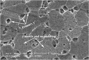
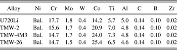
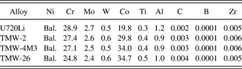
The chemical compositions of four tested Ni–Co base alloys are listed in Table I. All the alloys mainly consisted of matrix (γ phase) and precipitates (γ′ phase); the former has fcc crystal structure and the latter has L12 structure. The representative scanning electron microscopy (SEM) micrograph is shown in Fig. 1. More SEM images can be found in Ref. Reference Gu, Cui, Harada, Fukuda, Ping, Mitsuhashi, Kato, Kobayashi and Fujioka6. The compositions of γ matrix were calculated by using a Thermal-cal program with a Ni-RUMN database. The results are given in Table II. Ni content of the γ matrix actually decreases from 46.6 at.% in U720Li to 36 at.% in TMW-26, whereas Co content increases gradually from 19.8 to 34.7 at.% and Cr content decreases from 28.9 to 24.8 at.%. Other alloying elements, such as Mo, W, Ti, and Al, have relatively little variation.
Scanning electron microscopy micrograph showing the microstructure of U720Li alloy.

Chemical compositions of four Ni–Co base superalloys (at.%).

Chemical compositions of γ matrix in four Ni–Co base superalloys (at.%).

HRTEM is a powerful technique to reveal the core structure of dislocations.Reference Zheng, Li, Liu, Feng and Frommeyer12–Reference Hebert, Perepezko, Rösner and Wilde15 Usually in the fcc γ phase, a dislocation with Burgers vector of a/2 <110> can split into two Shockley partials with a stacking fault (SF) between them, which is called an extended dislocation.Reference Zhou, Preston, Lomdahl and Beazley16 If we view this configuration along the line direction of dislocation, both the Burgers vector of two partials and the SF width can be determined. Figure 2 shows the dissociation of a perfect matrix dislocation with Burgers vector a/2 <110> in TMW-2. The filtered HRTEM image, Fig. 2(b), clearly illustrates the SF existing between the two partials. The electron beam is along [ ], as indicated by the inset of diffraction pattern through fast Fourier transform in Fig. 2(a). The SF character is illustrated in the diffraction pattern by the nearly continuous line perpendicular to SF plane (11
 ). The dislocation line is parallel to the electron beam, i.e., end-on dislocation. The Burgers vector of the two partials has a projection component on the (
 ) plane, which can be determined by Burgers circuit, as seen in Fig. 2(b). The projection of the two Burgers vector has the opposite direction with the same magnitude of a/12[112], corresponding to the length of 30° Shockley partials projected on the (
 ) plane, respectively. If the Burgers circuit includes the whole extended dislocation, one can find no extra atom plane between two partial dislocations. The dislocation dissociation is:

(a) High-resolution transmission electron microscopy (HRTEM) image illustrates an extended dislocation in TMW-2. Inset is the diffraction pattern through fast Fourier transform, showing beam direction along [ ]. (b) Filtered HRTEM micrograph clearly shows the dislocation dissociation. The width between the two partials is about 5.0 nm.

For an extended dislocation, there exists the repulsive and attractive force between the two partials. The former originates from interaction of the partial dislocations themselves, whereas the latter is exerted by SF. Assuming that the two forces are in balance, the SFE can therefore be calculated from the following equationReference Aerts, Delavignette, Siems and Amelinckx17:

where γ SF is the SFE, G is the shear modulus, ν is the Poisson’s ratio, b is the Burgers vector of partial dislocation, d is the separation width of two partials (SF width), and Φ is the angle between line direction of the undissociated dislocation and the Burgers vector.
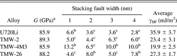
Here, the Poisson’s ratio of the different alloys was estimated to be ν = 0.31, similarly to what was used in IN783 alloy,Reference Feng and Kang18 b = 0.15 nm (assuming lattice parameter a = 0.36 nm), G is listed in Table III, d is approximately 5.0 nm, shown in Fig. 2(b), and Φ is 0°. By substituting the corresponding values, the SFE of γ matrix in TMW-2 from Fig. 2 is calculated to be 24.8 mJ/m2. To minimize the error of the calculated SFE, three other different extended dislocations in different area were also investigated. All the SF width measured is recorded in Table III. The final average SFE of γ matrix in TMW-2 is 23.4 ± 3.1 mJ/m2.
Parameters used for calculation and stacking fault energy in four Ni–Co–base alloys.

a Shear modulus at room temperature is calculated from the Young’s modulus we measured, considering the alloys as elastically isotropic.
b The dislocation before dissociation is a 60° dislocation, i.e., Φ = 60°.
c The dislocation before dissociation is a screw dislocation, i.e., Φ = 0°.
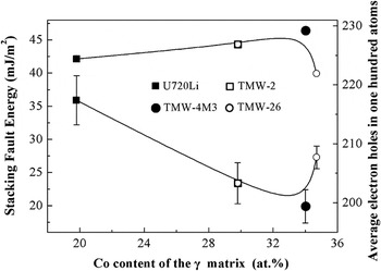
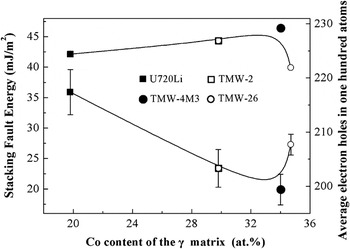
With the same method, the average SFE of γ matrix in U720Li, TMW-4M3, and TMW-26 was attained and is listed in Table III. The SFE as a function of Co content of γ matrix in Ni–Co base alloys is plotted in Fig. 3. It is clear that the SFE does not decrease monotonously with increasing Co content. Initially, the SFE decreases with increasing Co and reaches the lowest value, which is 19.9 ± 2.5 mJ/m2 in the γ matrix of TMW-4M3 alloy with Co content of 34.0 at.%, then it increases with further addition of Co.
The stacking fault energy (SFE) and electron holes as a function of Co content in the γ matrix of Ni–Co base alloys. The SFE is inversely proportional to electron holes.
It has been reported that Co has great influence on SFE in Ni–Co binary alloys.Reference Lee19, Reference Nie, Wang, Ye, Zhou and Wang20 However, the results even in Ni–Co binary alloys are not consistent. For example, the SFE do not have a linear relationship with Co content as illustrated in Ref. Reference Lee19, whereas theoretically calculated SFE has a linear relationship with Co content in Ref. Reference Nie, Wang, Ye, Zhou and Wang20. Xie et al.Reference Xie, Chen, Mchugh and Tien21 have reported an empirical formula to calculate the alloying effect on SFE in superalloys, suggesting the SFE decrease can be expressed as a coefficient of reduction times the at.% of that alloy addition. Unfortunately, this empirical formula cannot explain the nonlinear effect of Co content on the SFE in our experiments. Note that the Co content of γ matrix in TMW2, TMW-4M3, and TMW-26 exceeds the upper limit in Xie’s empirical formula, which is 22 at.%. The trend of Co effect on the SFE we found is similar with the result from Udimet 500 reported by Yang et al.Reference Yang, Xiao and Shi22 However, there is no W in Udimet 500, which is clarified to have an important effect on the SFE. Meanwhile, Udimet 500 has higher Cr content, whereas TMW alloys have higher Ti content. The different alloy compositions may cause the different Co content corresponding to the lowest SFE, which is 14.7 at.% in Udimet 500 and 24.0 at.% in TMW alloys. Yang et al. did not explain the reason for the trend of Co effect on the SFE and its relationship with the formation of twins in the alloys.
The SFE is related to the atomic bonding strength. From the viewpoint of solid state theory, electronic structure is usually thought as the main source of SFE. Electronic d-band of transition metals is not fully filled, which results in some unique properties not found in other elements. The relations between SFE, alloying element (transition metal) content, and occupancy of electronic d-band were already investigated in the past, and contradictory results were reported. According to Harris, the presence of empty d-states in Cu–Ni, Cu–Pd, and Ag–Pd alloys results in a large increase in the SFE.Reference Harris, Dillamore, Smallman and Beeston23 LeeReference Lee19 used Harris’ conclusion to argue that the introduction of hydrogen electrons into the d-band metals will cause a reduction of high density of states at the Fermi energy level N(E f), thereby decreasing SFE of Co–Ni, Fe–Ni, Cu–Ni, and Pd–Ag binary alloys. However, Harris’ conclusion cannot be applied to explain the decrease of SFE with increasing Co content in Ni–Co alloy, as calculated by an improved embedded-atom method.Reference Nie, Wang, Ye, Zhou and Wang20 The electron holes of Ni and Co per atom are 0.66 and 1.66, respectively.Reference Pauling24 The more addition of Co, the more electron holes (empty d-states) in Ni–Co alloy. More electron holes may be responsible for the decrease of SFE, which is contradictory to Harris. More recently, Yu and WangReference Yu and Wang25 calculated the influence of alloying elements, such as Re, Mo, Ru, Cr, W, and Co, on SFE by using density functional theory. Their results indicate that the bonding of Ni–Co is weak, so Co has less effect on SFE than other alloying elements under the same concentrations. This conclusion cannot be simply applied to TMW alloys since the Co content in TMW alloys is high and there are six alloying elements in TMW alloys. The effect of high-content Co on SFE in multiple alloying systems is more complicated than that in binary alloys.
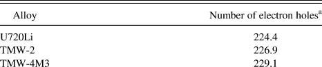
The average electron holes of 100 atoms in four alloys are calculated and given in Table IV; the equation is as follows:

Calculated average electron holes of 100 atoms in four alloys.

a The electron holes of alloying elements for Ni, Cr, Mo, W, Co, Ti, and Al are 0.66, 4.66, 4.66, 4.66, 1.66, 6.66, and 7.66, respectively.
where,  are average electron holes of 100 atoms, xi is atomic percentage of alloying elements in the matrix (listed in Table II), (Nh)i are electron holes of alloying elements per atom, which can be found in Refs. Reference Pauling24 and Reference Barrows and Newkirk26. It is found that the SFE is inversely proportional to
 , as shown in Fig. 3. Similar observation has also been reported by Ogwu in intermetallics who proposed that SFE is inversely proportional to N(E f).Reference Ogwu and Davies27 N(E f) is positively related to electron holes, i.e., more electron holes mean higher N(E f).
The bond in transition metals is mainly of d-character, and interatomic interactions are short ranged, so more electron holes may weaken the bonding between atoms.Reference Schulthess, Turchi, Gonis and Nieh28 Furthermore, we suggest there are two additional factors responsible for the increased SFE of the γ matrix with further addition of Co. First, the Co content may gradually saturate in the γ matrix. In Table I, the step of increasing Co content from U720Li to TMW26 is 47, 15, and 6%. However, in Table II, the corresponding increment of Co in the matrix is 51, 14, and 2%, respectively. Apparently, the increase of Co content in the matrix is not proportional with increasing Co content in the alloy, but seems to saturate. So further addition of Co will not decrease SFE of γ matrix any more. Second, when one considers the interactions of alloying elements, very high Co content may affect the partition coefficient of other alloying elements. For example, Cr content in TMW-4M3 and TMW-26 is the same, i.e., 14.7 at.%. However, Cr content in the matrix of TMW-26 is 24.8 at.%, which is lower than that of TMW-4M3, 27.1 at.%. Comprehensive effect of all alloying elements may cause the increase of SFE. More work needs to be done to accurately interpret these interacting effects.
Now it is clear that Co does have great influence on the SFE in Ni–Co base superalloys, and therefore affects the ability to form twins as well. Low SFE promotes the dissociation of perfect dislocations and facilitates the twin nucleation, resulting in high density of twins. The twinned structures are effective for improving the mechanical properties. This implies that mechanical properties can be tailored by controlling SFE during alloy design.
IV. CONCLUSIONS
In summary, the SFE of γ matrix in four Ni–Co base superalloys has been studied. We found the SFE had nonlinear relationship against Co content of γ matrix. The lowest SFE could be attained at approximate 34.0 at.% Co in the matrix of TMW-4M3. Low SFE could enhance the ability to form twins and introduce more twin structures into materials, which in turn improved the mechanical properties.
ACKNOWLEDGMENTS
The authors thank Prof. L.C. Qin at University of North Carolina, Chapel Hill, NC, for discussion and help to conduct HRTEM experiments. Y. Yuan is indebted to Dr. T. Nagai for the lecture of JEM 2100F at National Institute for Materials Science, Japan.