I. INTRODUCTION
Hardened steels having hardness of above 45 HRC can be classified as difficult to machining materials. In general, the hardened steels have been conventionally machined to finished geometries by abrasive process such as grinding operation. The process recommended for the hard machining is essentially a high wear resistance cutting tool with appropriate cutting conditions in finish process.Reference Jorge, Yume and Kwon1,Reference Dureja, Gupta, Sharma and Dogra2
Tool wear is one of the most complex phenomenon occurs during hard machining. The tool wear leads to degrade in surface quality (white layer formation) and increases tensile residual stresses on the machined surface.Reference Dureja, Gupta, Sharma and Dogra2,Reference Khrais and Lin3 The cutting tool life must be carefully observed in the turning of hard materials, since it is a finishing process requiring better surface finish comparable to grinding operation. The tool wear in hard turning is influenced by various parameters, such as cutting conditions, workpiece hardness, tool material and interaction of tool-workpiece, and so on. Generally, the cutting tool performance is limited by flank wear, nose wear, crater wear, edge chippings, or combination of these. The tool wear either occurs gradually by adhesive or abrasive wear, through plastic deformation, and discrete fracture mechanism, or by combination of these.Reference Dureja, Gupta, Sharma and Dogra2,Reference Khrais and Lin3 The occurrence of each wear mechanism depends on high thermal, mechanical, and chemical loads generated in hard machining. Carbide cutting tools are the regular tools for machining of alloy steels and cast iron. These cutting tools have a high degree of toughness but poor hardness compared to advanced tool materials, such as cermet's, ceramics and polycrystalline cubic boron nitride (PCBN).Reference Mari and Gonseth4 To improve the hardness and surface conditions, carbide tools are coated with hard coatings, such as TiN, Ti(C,N), (Ti,Al)N, (Zr,C)N, Al2O3, and so on.
Today, the majority of carbide tools use physical vapor deposition (PVD) or chemical vapor deposition (CVD) of hard coatings. The high wear resistance, hot hardness, and chemical stability of these coatings provided maximum benefits in terms of high machining performance and longer tool life.Reference Prengel, Pfouts and Santhanam5 The CVD coated carbides have been a huge success since their introduction in the late 1960s.Reference Venkatesh, Ye, Quinto and Hoy6 Since then, CVD technologies have advanced from single layer to multilayer coating with various combination of TiN, Ti(C,N), TiC, (Ti,Al)N, and Al2O3.Reference Bonetti, Wipraechtiger and Mohn7 The modern CVD coatings combine moderate temperature and high temperature processes in complex cycles that produce high wear resistant coatings with total thickness of 4–20 μm.Reference Prengel, Heinrich, Roder and Wendt8
Several researchers investigated the effects of hard machining on different types of cutting tools, such as cemented carbides, ceramics, and extra-hard materials (e.g., CBN, PCD etc.). The cemented carbides are made by a mixture of tungsten carbide (WC) micro grains with cobalt at high temperature and pressure. Titanium, tantalum or vanadium carbides can also be mixed in small proportions. This type of material in the straight grade or in the coated grades is mostly used today for hard machining and high-speed machining. A cemented WC also contains TiC and in some cases TiCN, but they normally have a nickel–chrome binder. The cemented carbides are very stable with respect to chemical and thermal aspects of machining. In most of the cases, cemented carbide degradation starts from the cobalt binder and the WC–cobalt cohesion.Reference Davim9
Ghani et al.Reference Ghani, Choudhury and Masjuki10 studied the tool wear mechanism of TiN coated carbide and uncoated cermets tools in machining of hardened AISI H13 tool steel. The results of their investigation indicated that both the inserts experience uniform and gradual wear on the flank face, and diffusion and oxidation have also been experienced under higher cutting conditions. Arsecularatne et al.Reference Arsecularatne, Zhanga and Montross11 investigated the tool wear behavior and tool life for WC and PCBN cutting tool during machining of AISI 4142, AISI 1045, and AISI 52100 steels. Their investigations revealed that the most dominant tool wear mechanism for WC is the diffusion and for PCBN is chemical wear. AslanReference Aslan12 studied the wear behavior coated carbides, cermet, and ceramic inserts in machining of hardened AISI D2 tool steel. They found that the cermet and TiAlN coated carbide tools perform marginally better than TiCN coated carbide tool, which can be attributed to better high temperature properties of TiAlN compared with TiCN.
Cho and KomvopoulosReference Cho and Komvopoulos13 studied the performance of two layer and three layer coated carbide tools in hard turning process. The experimental results indicated that three layer coated (TiC/Al2O3/TiN) tools have high wear resistance compared with the two layer coated (TiC/Al2O3) tools. Bouzakis et al.Reference Bouzakis, Hadjiyiannis and Skordaris14 investigated the influence of the coating thickness on its strength properties and performance of PVD coated inserts. The results showed that the film failure development after the coating fracture initiation was less intense in the case of the multilayer coated tool.
Park and KwonReference Park and Kwon15 investigated the flank wear study on the multilayer coated carbide tool. They concluded that the hardness of the coating is the most important constraint to resist flank and crater wear due to its high wear resistance against abrasion in hard machining. Sahoo and SahooReference Sahoo and Sahoo16 performed experimental investigations on hardened AISI 4340 steel using uncoated and multilayer coated carbide tools during finish turning operations. They observed that multilayer coated (TiN/TiCN/Al2O3/TiN) carbide tool performed better and longer tool life than uncoated carbide tool.
CiftciReference Ciftci17 experimentally investigated the behavior of multilayer coated carbide tools in turning of hardened austenitic steels (AISI 304 and AISI 316). It was observed that the outer layer TiN coating has lower coefficient of friction than Al2O3 coating. The results showed that cutting speed plays a dominant role in determining the tool life. Noordin et al.Reference Noordin, Venkatesh and Sharif18 have found better performance by multilayer coated (TiCN/Al2O3/TiN) carbide inserts against TiCN coated cermet in turning of hardened stainless steel (50 HRC). Knutsson et al.Reference Knutsson, Johansson, Karlsson and Oden19 have illustrated the machining performance of TiAlN/TiN multilayer coated cutting tools. The results indicated that the TiAlN/TiN coating improved the tool life and thermal stability.
Avila et al.Reference Avila, Godoy, Abrao and Lima20 studied the topographic analysis of the crater wear on TiN, Ti(C,N), and (Ti,Al)N coated carbide inserts during the turning of hardened AISI 4340 steel. The results confirmed that the (Ti,Al)N coating is most desirable in dry machining at high speeds. Further, they also found the higher crater wear resistance with (Ti,Al)N followed by TiN and Ti(C,N) coated tools. Aneiro et al.Reference Aneiro, Reginaldo and Lincoln21 have studied the machining characteristics of hardened steel with multilayer coated (TiCN/Al2O3/TiN) carbide and PCBN tools. The results indicated that superior tool life could be achieved by using PCBN inserts, but cost wise PCBN insert is as thrice as that of the multilayer coated carbide tool. They suggested that the machining medium hardened steel with multilayer coated tools tends to be more productive.
The explanation for the high performance of multilayer CVD coated (TiN/MT TiCN/Al2O3) over single layer coated tool can be attributed mainly due to the following factors. Firstly, multilayer coating acts as thermal barrier against crack initiation, when fatigue stresses are created by the frequent formation and chip removal that adheres to the tool face. Moreover, the multilayer coating offers to multifunction to the tool, namely, thermal protection and high crater wear resistance at top layer (Al2O3), high wear resistance by intermediate layer (TiCN) and lower friction and strong adhesion by the innermost layer (TiN).Reference Ciftci17 It can be deduced that abrasive wear is the dominant wear mechanism at lower cutting conditions and abrasion and diffusion at higher cutting conditions. In view of the above, the better performance of coated carbide inserts on machining of hard steels relied on coating combination of layers, which seems to be the adequate one for hard machining.
The literature review reveals that limited number of works available pertaining to tool behavior of multilayer coated carbide tools and also these tools come at lesser cost when compared with ceramic and PCBN tools.Reference Ezugwu, Silva, Bonney and Machado22 However, their usages to the turning of hardened steel in the range of 48–55 HRC are lacking. Hence, a detailed experimental investigation is vital to have systematic and scientific study for the implementation of multilayer coated carbide tools in hard machining. Hence, in the present work, attention is paid to evaluate the performance of multilayer coated (TiN/MT TiCN/Al2O3) carbide inserts in turning of hardened AISI 4340 steel (48 HRC) under varying cutting conditions.
II. EXPERIMENTAL DETAILS
Commercially available AISI 4340 high strength low alloy steel bars of diameter 100 and 400 mm length, hardened to a hardness of 48 HRC were used as workpiece materials. The chemical composition of AISI 4340 steel is given in Table I. Cutting tests were carried out on a “Mazak” CNC lathe under dry conditions. The lathe is equipped with 22 kW spindle power and maximum spindle speed of 5000 rpm. The photograph of the experimental setup is shown in Fig. 1.
The chemical composition of AISI 4340 steel in percentage by weight.

Experimental setup.

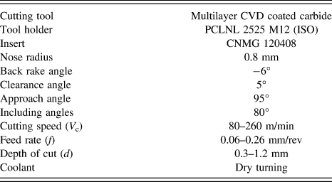
The multilayer coated carbide inserts of ISO grade (KCP05) were used in the present investigation. The inserts had multilayer CVD coated (TiN/MT TiCN/Al2O3) on cemented carbide substrate. The overall thickness of the coating is 8 µm (layer thickness of TiN-2 µm, TiCN-2 µm, and Al203-4 µm). The hardness of the coated tool is 2160 HV and thermal conductivity is 28 W/m K. The coating consists of a thick CVD deposition of TiN for low coefficient of friction and heat resistance with moderate temperature of TiCN for thermally stable and high wear resistance and outer most layer of Al2O3 for crater wear and heat resistance. The details of tool geometry and cutting conditions are outlined in Table II.
Specifications of the cutting tool and cutting conditions.
To analyze the effects of machining parameters on tool wear, the experiments were conducted at different levels of individual parameters. Cutting conditions were specified in accordance with recommendations from the insert supplier for considered applications. In each experiment, fresh cutting tool was used and the experiments were repeated twice under each cutting condition to limit the experimental error at minimum and average values are used. The average flank wear was limited to 0.3 mm and it was selected as the tool life criterion. After the machining test, the average width of flank wear was measured using precision “Nikon” optical microscope (magnification: 500x and resolution: 1.0 µm). Scanning electron microscope (SEM) and elemental analysis (EDAX) system were used to analyze the tool wear mechanisms.
III. RESULTS AND DISCUSSION
A. Effect of cutting speed on tool wear
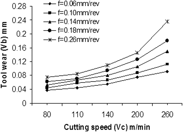
Figure 2 shows the wear behavior of multilayer coated carbide tool in relation to cutting speed (V c)–feed rate (f) interactions at constant depth of cut (d) of 0.6 mm and cutting time (t) of 4 min. Figure 2 shows that tool wear increases with increase in cutting speed for all values of feed rates and sensitive to variations of feed rates with specified cutting speeds. The results indicated that the cutting speed of 80 m/min and feed rate of 0.06 mm/rev produced lowest flank wear of 0.036 mm, where cutting speed of 260 m/min and feed rate of 0.26 mm/rev resulted in the highest amount of flank wear of 0.23 mm. As seen from Fig. 2, the cutting speed increases from 80 to 140 m/min, the wear rate increases relatively. It was known that with the increase of cutting velocities the flank wear increased and the tool wear is caused by abrasion. The increase in cutting speed from 140 to 200 m/min leads to rapid rubbing action between tool and workpiece thus generates heat, even though less contact time exits. It causes thermal softening of tool on flank face and more abrasive wear occurs.
Variation of tool wear against cutting speed at various feed rates and constant d = 0.6 mm and t = 4 min.
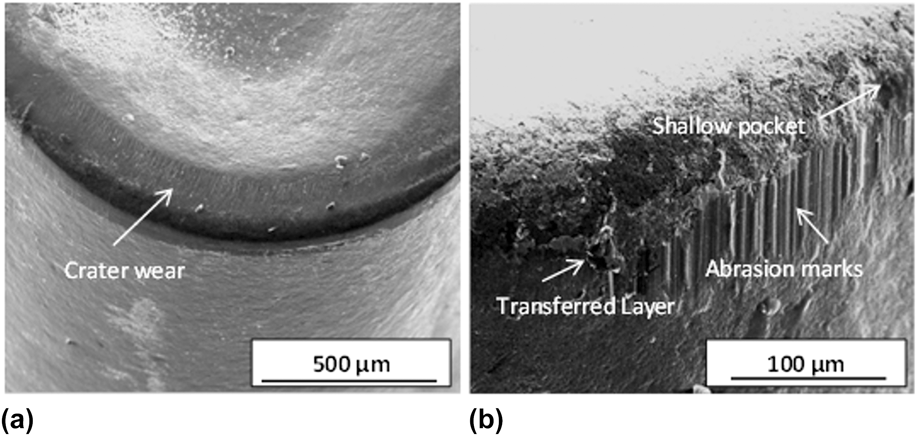
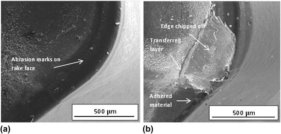
Figure 3 shows the SEM views of the tool wear profile of coated carbide tools. It indicates that the flank, rake, and nose wears were severely worn under higher cutting conditions. The ridges and deep plowing grooves are clearly evident on the tool flank face and it is indicative of typical abrasive wear. It clearly shows that the increase in cutting speed causes rapid tool wear and consequently reduces the tool life. At higher cutting conditions, the insert edge undergoes an accelerated wear caused due to high pressure and temperature.Reference Lee and Mathew23 The reason is that the serrated chips abrade the tool rake face and create scars in the rake wear surface. The evidence for the short saw toothed loose arc types chips obtained are shown in Fig. 4.
SEM images of crater wear effect observed on the rake face of the tool at (a) V c = 140 m/min, f = 0.10 mm/rev, and d = 0.6 mm and (b) V c = 260 m/min, f = 0.14 mm/rev, and d = 0.6 mm.
Chip formations at (a, b) V c = 140 m/min, f = 0.1 mm/rev, and d = 0.3 mm and (c, d) V c = 260 m/min, f = 0.14 mm/rev, and d = 0.6 mm.
At lower cutting conditions of V c = 140 m/min, f = 0.1 mm/rev, and d = 0.3 mm, tubular structured coiled type chips were observed [see Figs. 4(a) and 4(b)] and also minor crack initiation on the outer surface of the chip was evidenced. On the other hand, short saw toothed chips with upside curling were observed at V c = 260 m/min, f = 0.14 mm/rev, and d = 0.6 mm. [see Figs. 4(c) and 4(d)]. The nature of chips at above conditions is due to effective machining because of complete shearing of workpiece leading to plastic deformation.
From the above, it is clearly indicated that abrasion action causes the wear on rake face to be attributed by sliding of the saw tooth chips on rake face. The coated layer on the rake face and flank face becomes soft. Under such conditions, hard particles of the workpiece material abraded and accelerate the tool wear. Therefore, the life of coated carbide tools would gradually be reduced. It indicates that the tool wear is concentrated typically on the nose region because of high stresses and thermal softening of tool material due to elevated temperature at this region. It can be concluded that the coated carbide cutting tools exhibit better performance at lower cutting speed and feed rate during turning of hardened steel.
B. Effect of feed rate on tool wear
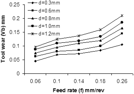
Figure 5 shows the wear behavior of multilayer coated carbide tool in relation to feed rate (f)–depth of cut (d) interactions at constant cutting speed of 200 m/min and cutting time of 4 min. The tool wear increases relatively with increasing feed rate from 0.06 to 0.14 mm/rev, while it increases rapidly with further increase in feed rate of 0.18 mm/rev. Increased feed rate causes increase in material removal rate, but feed rate has detrimental effect on tool life. The results showed that the maximum flank wear observed at higher feed rate of 0.26 mm/rev and depth of cut of 1.2 mm is 0.22 mm.
Variation of tool wear against feed rate at various depth of cuts at constant V c = 200 m/min and t = 4 min.
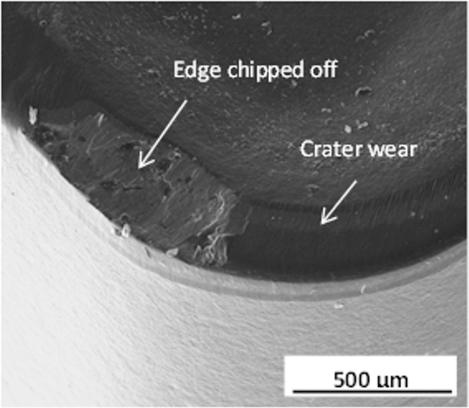
The formation of the wear at higher feed rate and depth of cut is largely due to the contact between tool and workpiece interface. Hence, it leads to the cutting tool to suffer rapid wear, chipping or fracture. The chipping/fracture of the cutting edge was clearly evidenced (see Fig. 6), which clearly indicates prominent tool wear at higher values of feed rate and depth of cut. The reason might be, with increased feed rate, the temperature increases and the stress generated on the rake and flank faces close to the nose area probably causes the reduction in yield strength of the tool.Reference Huang and Dason24
SEM image of crater wear effect observed on the rake face of the tool at V c = 200 m/min, f = 0.26 mm/rev, and d = 1.0 mm.
C. Effect of depth of cut on tool wear
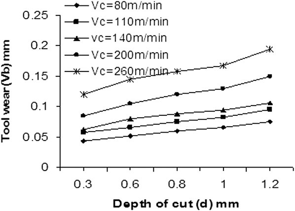
Figure 7 shows the wear behavior of multilayer coated tool in relation to depth of cut (d)–cutting speed (V c) interactions at constant feed rate (f) of 0.14 mm/rev and cutting time (t) of 4 min. It is observed that the tool flank wear linearly increases with increase in depth of cut for all the values of cutting speed selected in the range of 80–140 m/min. The tool flank wear increases from 0.07 to 0.13 mm with increase in depth of cut from 0.3 to 1.2 mm. When the depth of cut increases, the specific contact stress at the tool–chip interfaces and average contact temperature remain unchanged.Reference Astakhov25 The increase in tool wear is probably due to abrasive grooves at the rake face of the cutting tool. Therefore, an increase in depth of cut does not change the tool wear rate at the cutting speed of 80 to 140 m/min. However, the tool wear is highly perceptive to variations in depth of cut with higher cutting speed of 140–260 m/min.
Variation of tool wear against depth of cut at various cutting speeds at constant f = 0.14 mm/rev and t = 4 min.
D. Effect of cutting time on tool wear
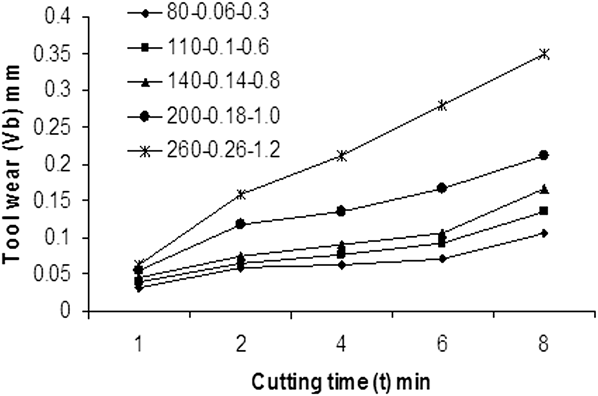
Figure 8 shows the effect of tool flank wear on machining time under various cutting conditions of cutting speed of 80 to 260 m/min, feed rate of 0.06 to 0.26 mm/rev, and depth of cut of 0.3–1.2 mm, respectively. It can be clearly observed that the tool wear trend obeys the universal wear law of any mechanical workpiece (running into wear, semisteady state or gradual wear and accelerated wear). There is an increase in the cutting conditions as a function of cutting time. Figure 9 shows the worn surfaces after 2 min [see Figs. 9(a)–9(c)] of cutting time and their final states after 8 min [see Figs. 9(d)–9(f)] of tests at cutting speed of 140 m/min, feed rate of 0.14 mm/rev, and depth of cut of 0.8 mm. It is observed that the tool wear after 4 min of cutting time is around 0.065 mm. The tool flanks wear increases to 0.18 mm relatively with increasing the cutting time to 8 min. It indicates that during the beginning of the cutting, the wear at flank face and nose was uniform. Further increasing in cutting time caused the wear width at the nose to increase faster than that at the flank face. These figures indicated that the flank wear progress is steadier during machining, while the crater formation on the rake face is highly influenced by thermal conditions and associated chemical wear of the tool material.Reference Tamizharasan, Selvaraj and Noorul Haq26
Variation of tool wear against cutting time at different cutting combinations of cutting speed (V c), feed rate (f), and depth of cut (d).
Micrographic images of worn cutting edges at V c = 140 m/min, f = 0.1 mm/rev, d = 0.8 mm (a–c) t = 2 min and (d–f) t = 8 min.
From Fig. 9(f), it can be observed that extensive crater wear occurred on the rake face of the tool. In addition, worn zone is extended below the cutting edge causing the creation of a deep triangular groove. Generally, adhesion, abrasion, and diffusion type of tool wear mechanisms are observed in hard machining with CBN cutting tools.Reference Huang and Dason24,Reference More, Jiang, Brown and Malshe27 However, in the case of hard machining with carbide tools, their comparatively lower hardness makes abrasion of the dominant wear mechanism.
Similarly, Figs. 10(a)–10(f) show the micrographic images of worn cutting edges under higher cutting conditions. As cutting time elapsed, thermal softening of the cutting edge causes rapid wear and chipping or fracture occurred within few minutes of machining which is observed from micrographic views. It indicates that at extreme cutting conditions, carbide tools were incompetent to withstand high temperature and pressure at cutting zone hence rapid tool wear occurred. Moreover, it confirms that the origin of grooves is attributed to the tool binder damage caused by hard carbide particles of the workpiece leading to carbide tool grains falling out when machining hardened steel with a carbide tool. Similar discussion can be found elsewhere Luo et al.Reference Luo, Liao and Tsai28 It can be deduced that the measurement of progressive tool wear is one of the important parameter to determine the tool life.
Micrographic images of worn cutting edges at (a–c) V c = 200 m/min, f = 0.18 mm/rev, d = 1.0 mm, t = 8 min and (d–f) V c = 260 m/min, f = 0.26 mm/rev, d = 1.2 mm and t = 8 min.
E. Tool wear mechanism and failure mode
When the SEM images [see Figs. 11(a) and 11(b)] of worn cutting edges are closely examined, the extreme tool wear observed under higher cutting conditions. In Fig. 11(a), uniform crater wear and flank wear were observed on the cutting edge at cutting speed of 140 m/min, feed rate of 0.10 mm/rev, and depth of cut of 0.3 mm. These uniform grooves on the flank face resulted from the abrasion of the hard carbide particles of the workpiece material. It can be concluded that abrasion is the dominant wear mechanisms when machining with multilayer coated carbide tools.
SEM views at different cutting conditions of (a) V c = 140 m/min, f = 0.1 mm/rev, and d = 0.3 mm (b) V c = 260 m/min, f = 0.26 mm/rev, and d = 0.6 mm.
Fig. 11(b), it is observed that maximum wear occurred on the rake face of the tool at cutting speed of 260 m/min, feed rate of 0.26 mm/rev, and depth of cut of 0.6 mm. The most important factors influencing crater wear were higher temperature at the tool tip interface and the chemical affinity between tool and work materials.Reference Tamizharasan, Selvaraj and Noorul Haq26–Reference Poulachon, Bandyopadhyay, Jawahir, Pheulpin and Emmanuel29 The formation of crater wear while turning of hardened AISI 4340 steel was more due to flow of saw tooth chips on rake face. The saw tooth chips have rough surface which rubs the rake face. At higher cutting speeds with low feed rate was also responsible for crater wear. To confirm through EDAX pattern of the worn-out insert test showing the presence of oxygen element, the built-up layer consists of Fe element, which is the constituents of work material (see Fig. 12). EDAX pattern also reveals the presence of elements like Ti and Al, which are present in the binder phase of the multilayer coated carbide tool. Moreover, at high cutting conditions, coating is rapidly smeared out and the insert behaves like a bared tool. The cutting edge is unable to bear the abrasive action of the chip; the heat generated and consequently fails at faster rate. This reduces the life of the cutting tool and adversely affects the surface quality of the machined surface. In general, abrasion and diffusion type of wear mechanisms are predominantly observed under higher cutting conditions during hard turning.
EDAX pattern of the worn-out tool (magnification: 500x and 20.0 kV) at V c = 260 m/min, f = 0.26 mm/rev, and d = 0.6 mm.
IV. CONCLUSIONS
In the present study, the tool wear was analyzed to investigate the effects of cutting conditions during turning of hardened AISI 4340 high strength low alloy steel using multilayer coated carbide (TiN/MT TiCN/Al2O3) insert. Based on the experimental results, the following conclusions are drawn within the ranges of the process parameters selected:
(1) The tool wear increases with increase in cutting speed for all values of feed rates and it is sensitive to variations of feed rate and depth of cut with specified cutting speeds.
(2) Abrasive wear was the dominant wear mechanism observed under lower cutting conditions, and abrasion and diffusion under higher cutting conditions. Intermittently, sudden fracture (chipped off/diffusion) occurred after longer cutting times.
(3) At higher cutting speed and feed rate, the increased cutting temperature results in the oxidation of binder material, exposing of the some of the substrate particles on tool flank and rake faces. These particles are severely abraded by the hard carbide particles exciting in the workpiece material causes accelerating the tool wear.
(4) The multilayer coated (TiN/MT TiCN/Al2O3) carbide tool wear can be minimized by using lower feed rate, depth of cut with average cutting speed (around 80 to 140 m/min).
ACKNOWLEDGMENT
The authors are thankful to Kennametal India Ltd., Bangalore, India for providing facilities to conduct experiments and also support for the entire work.