Introduction
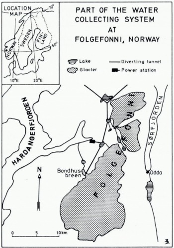
All electrical energy in Norway is produced by hydro-electric power stations. Some of these receive their water from high mountain-drainage basins, where the water is collected in a main reservoir at a high altitude. At the Mauranger power station, situated at the Hardangerfjord south of Bergen (Fig. 1), it was decided to locate the main reservoir at an altitude of about 850 m a.s.l. All galleries collecting water from various streams and creeks (in total from 162 km2) must therefore be placed at a slightly higher altitude. One of the large water resources in this project is a part (62 km2) of the Folgefonni ice cap. Bondhusbreen, one of the outlet glaciers from this ice cap, draining a part of it, penetrates down the valley to an altitude of about 450 m, so melt water could not be collected at the glacier terminus unless it was pumped up to the collecting tunnel. It was therefore decided to make a subglacial water intake under this outlet glacier (Fig. 2).
Location map showing a generalized outline of the Folgefonni ice cap and part of the water-collecting system (bedrock galleries) for the hydro-electric power station at Hardangerfjorden.

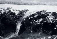
An oblique air photograph showing the steep outlet glacier Bondhusbreen draining north-westwards from the ice cap.

Bondhusbreen extends from the dome-shaped part of the Folgefonni ice cap at 1 630 m a.s.l., the length of its flow line is approximately 6 km and its total area is 12.3 km2. The ice cap itself rests on a gneissic granite, which forms an almost horizontal sub-Cambrian peneplain. The outlet glaciers, such as Bondhusbreen, have eroded valleys down below the former peneplain, in general along tectonic joints and faults.
Technical Investigations
Hot-point drilling
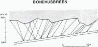
It was necessary to determine the bedrock topography in the area where the subglacial intake was to be located. Seismic methods proved useless because of the narrow valley and the many deep crevasses which introduced so much noise that no reliable results could be obtained. Therefore, it was decided to determine the ice thickness by hot-point drilling at a large number of points in a cross-section of the glacier. Electric hot points were run simultaneously by a powerful generator placed on the glacier and 12 vertical holes penetrated about 150–170 m of glacier ice. The results of this operation indicated that there existed three independent depressions in the cross-sectional profile (Fig. 3). A bedrock tunnel was then constructed beneath the glacier.
A rough cross-section was constructed from 12 hot-point drillings, but details in the bedrock topography could not be determined by this method.

Soundings through the bedrock
To check the results from the above-mentioned hot-point drillings and to obtain a more detailed picture of the bedrock topography, a number of drillings were made from the roof of the tunnel to the glacier sole by means of diamond drills. Such drillings were definitely necessary to obtain a sufficiently detailed knowledge of the ice/bedrock interface before further tunnelling was made to the glacier.
The drillings indicated that the ice was slightly thicker than the hot-point drillings had shown, the difference was in the order of 20 m (Fig. 4). This systematic error might be a result of debris collecting at the bottom of the holes melted by the hot point or that the hot point itself struck an englacial stone before it reached the sole of the glacier. Another reason for the discrepancy could be that the hot-point drillings were not made at exactly the same location as the bedrock drillings, since the hot-point drillings were made in a heavily crevassed area. Only a small inaccuracy in positioning might cause relatively large errors in ice-thickness determination.
A better knowledge of the subglacial bedrock topography was obtained by rock drillings from the roof of a tunnel under the glacier. The existence of three possible drainage channels was discovered by this operation.

Technical experience
All the efforts over several years to determine the ice/bedrock interface have given valuable experiences—particularly valuable for future operations of a similar kind. The chief engineer, Mr H. Døhlen, has therefore summarized the most important points from his experience in a special technical report (Reference DøhlenDøhlen, 1977). Some of the main points of this report are mentioned here to give glaciologists and engineers an idea of possible solutions to many practical problems.
An almost horizontal tunnel must be constructed more or less at right-angles to the glacier movement. Ideally, this tunnel should be constructed not more than 5–10 m below the deepest point in the cross-sectional profile. This requires that the ice/bedrock interface must be determined with a high degree of accuracy. Hot-point drilling proved to give slightly lower values for the glacier thickness and other methods have so far not given sufficiently accurate results, at least under conditions such as those at Bondhusbreen.
As soon as this horizontal tunnel has been constructed, it is possible to draw a very accurate cross-sectional profile by drilling vertical holes up from the roof of the tunnel. Local depressions in the cross-sectional profile, i.e. “local valleys” where subglacial drainage channels could be expected, can then be easily detected provided the distances between the “sounding holes” are selected carefully.
A contour map showing the ice/bedrock interface must be constructed, based on the information obtained by drillings. Further, new tunnels might be required to reach potential areas for water intakes. Finally, relatively small tunnels must be made up to the glacier sole to start melting of ice caves or subglacial tunnels for detailed inspection of bedrock topography at potential intake areas.
It may be possible to locate existing subglacial drainage channels by one of the following methods:
-
i. Acoustic observations might reveal noise in areas of running water, particularly if the water is carrying small rocks and stones. This can be verified by vertical drillings (from the horizontal tunnel) to find the water-carrying channel.
-
ii. Chemical tracers can be injected in melt-water holes up-glacier. The vertical sounding holes in the tunnel roof will normally carry some water during the summer, but some of the water might only be melt water produced locally near the hole. The tracer method can indicate whether or not the water originates from a larger part of the glacier.
The construction of oblique bedrock tunnels (for water intakes) causes, in general, no technical problems except when the tunnel reaches the upper parts of the bedrock. Heavy layers of compacted and/or frozen morainic material may be found before one reaches the glacier ice. The penetration of these layers may be difficult and dangerous so it is necessary to protect workers by making a solid “roof” of a part in the tunnel’s cross-sectional area.
Problems of solid matter
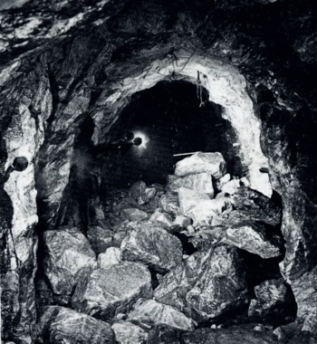
Some early measurements of the ice velocity indicated that the ice surface at Bondhusbreen moved faster than 100 m year−1. This considerable ice discharge was expected to cause fairly extensive erosion and this was confirmed by sediment-transport studies at the front of the glacier. During the summers of 1972 and 1973 an annual amount of about 7000 metric tons was moved by the stream and a bed load of almost the same size was also observed (Reference ZieglerZiegler, 1974; Reference HaakensenHaakensen, 1975). It was therefore necessary to solve the problem of coarse material carried by the melt water below the glacier, because such material should not be allowed to enter the diversion tunnels. These are almost horizontal and could therefore be filled up by material carried as bottom load (Fig. 5).
Coarse material carried by melt water from a subglacial intake during the summer of 1974. Such material must not be allowed to enter the almost horizontal diversion tunnels (the galleries).

It was therefore decided to construct a sedimentation chamber in the bedrock beneath the glacier. The size of this sediment trap had to be made large enough to take care of the total bottom load during any summer, even during a summer with abnormal high melt-water drainage.
To determine the highest possible annual amount of transported material, a special study was made at the glacier front and in Bondhusvatn, a small lake not far from the glacier tongue (Reference ZieglerZiegler, 1974; Reference HaakensenHaakensen, 1975; Reference Østrem and OlsenØstrem and Olsen, 1975).
Calculations based on field observations in 1972 and 1973 in the river between the glacier and the lake indicated that the suspended sediment and the bottom load were of approximately the same amount. For the engineering problems, only coarse bottom-load material was of interest but suspended sediment is much easier to observe. Furthermore, previous years’ transport of suspended material in the glacier stream is in fact recorded on the bottom of the lake because 70-80% of such material is deposited in the lake.
Bottom samples, taken by a piston corer, revealed that annual varves were present and they could be relatively easily recovered from the last 200–300 years of sedimentation. The thickest varves must have been deposited during years of large sediment transport and such years were also considered to represent the largest bottom load. The five heaviest deposits during the last 200 years were therefore carefully examinated and the total amount of suspended load in the glacier stream was calculated for these years. This study indicated that as much as 8000m3 of coarse material may be expected during a year of exceptionally high water discharge, so the sedimentation chamber had to be dimensioned accordingly. This means that the chamber will normally not be filled completely during an average summer. The material must be removed from the chamber during the winter to leave space for the following summer’s deposits. Technical installations were constructed for this operation which will take place normally during the months Januarys–March, when practically no water is draining and the sedimentation chamber can be emptied by bulldozers and trucks. The material can then be transported through a special tunnel and dumped back on to the glacier (cf. Fig. 7).
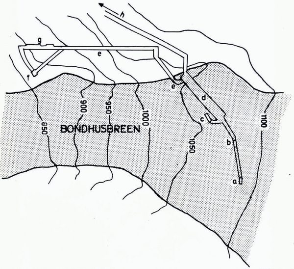
Sketch showing the main subglacial tunnel system: a, the south-western intakes; b, the middle intakes; c, the northeastern intakes; d, the large sedimentation chamber; e, spillway and unloading tunnel; f, the helicopter landing platform and the mess; g. workshop and storage; h, the diverting tunnel leading the collected water to the main reservoir.

Ice-velocity measurements
Ice movement at the glacier surface
The surface movement of the glacier ice has been observed several times during the last few years in an area just above the subglacial intake points (Fig. 6). Several stakes were drilled into the ice and their movement was determined by standard triangulation methods from three fixed points on the valley sides. The results of these observations are given in Table I.
Stake positions and triangulation points for ice-surface velocity measurements. The subglacial water intake is located under the 1100 m contour line.


The variation in average daily velocity is either based on a real change in ice velocity or different ice velocities at different locations, i.e. the velocity seems to change when the stake moves away from the original observation area. To eliminate this possible error, the stakes in positions 10 and 20 were moved back to exactly the original location before a new velocity measurement was made. For this purpose, two theodolites were placed in triangulation points Tp II and III, and the exact positioning of the stakes was then secured.
Repeated observations were made on 15 June and 21 September 1977. In addition to the stakes in the two above-mentioned positions, four other stakes higher up-glacier were also surveyed. The results are shown in Table II.
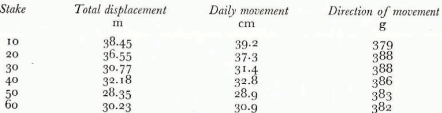
In stake positions 10 and 20 additional observations were made to determine the movement within 24 h. The stakes were then placed exactly in a straight line between Tp II and Tp IV. After 24 h a metric stick was held horizontally at each of the stakes and the movement could be directly read by theodolite. The two stakes had then moved 33 and 30 cm, respectively, between 15 and 16 June, whereas for the 24 h period 20–21 September the corresponding figures were 34 and 31 cm.
If we compare these measurements made on 15–16 June and on 20–21 September with the daily mean velocity throughout the entire summer, it is clear that the summer mean indicates a 15–20% higher velocity than the point measurements. It is difficult to explain this; one possibility could be that the measuring points moved closer to the ice fall during the summer, hence, giving a higher velocity. However, the horizontal displacement is only 37–38 m and the glacier’s surface slope and cross-sectional profile are practically unchanged in this area.
Another explanation could be an assumed fluctuation in ice velocities in general. It is possible that the glacier moved faster during the summer (or during parts of the summer). Meteorological observations indicate that the ice-melt conditions during the measurements in June and September were very close to the mean melting rate of the entire summer. It is possible, however, that during short periods of extreme melt the glacier may have moved faster and thus caused a higher mean velocity during July and August. Reference Müller and IkenMüller and Iken (1973) have shown that short-term discharge variations have a pronounced effect on glacier movement.
During the period 24 September 1976–16 June 1977, a stake was placed just below the ice fall (Fig. 6). The movement of this stake had been calculated from simple angle measurements from one point and distance measured by tape. The calculated result indicated a glacier movement of 50 cm d−1 during the winter on this lower part of the glacier.
Ice movement at the bottom of the glacier
Some ice-velocity measurements were attempted at the bottom of the glacier. Due to the deformation of the ice tunnel by the ice pressure, it proved difficult to make meaningful measurements. However, some of the observations indicated that the glacier ice in the cave was moving at a speed of approximately 10–20 cm d−1, which is about half of the ice velocity observed at the glacier surface. The ice movement at the bottom of the glacier seemed partly to be bottom sliding and partly differential movement along shear planes in the lower metre of the glacier ice.
Subglacial observations
Ice caves
The vertical bore holes made from the roof of the bedrock tunnel could not give a sufficiently detailed picture of the ice/bedrock interface. It was particularly important to obtain a more detailed picture of the bedrock topography to discover where the water usually flows.
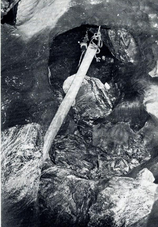
Therefore, ice caves were melted by a hot-water spraying method in the bottom layer of the glacier from narrow tunnels constructed from the main, almost horizontal, tunnel below the glacier (sec Fig. 7). This method had been used previously in France and it also proved satisfactory at Bondhusbreen. Hot water at a temperature of 4O-50°C was sprayed through a special nozzle (Fig. 8). The return water had a temperature of 0–5°C; a higher initial temperature would only have produced more water vapour in the tunnel and the return water would have been unnecessarily warm. Ice tunnels, 30–40 m in length were made in various directions from the above-mentioned bedrock tunnels to map the ice/bedrock interface.
From the melting operation, making ice caves and tunnels near the ice/bedrock interface. Hot water is pumped through hoses to a nozzle kept in position by ice screws.

The hydrostatic pressure under about 150–170 m of ice caused a major problem; the ice caves were closing fairly rapidly. Measurements made in the various ice tunnels revealed a compression of the tunnels by 10–20 cm d−1. This was partly due to lowering of the roofs and partly to movement of the walls into the tunnels. Most of these measurements showed a decreased tunnel diameter of 15–16 cm d−1. The deformation-rate seemed to be independent of the size (diameter) of the tunnel. Part of this deformation was eliminated by ice melting due to the relatively high air temperature caused by the spraying operation. By continuous spraying the air temperature in the tunnel was approximately +3°C and both the walls and roof melted away at a rate of approximately 3cm d–1. The deformation of the ice caves seemed to be very steady and no sudden movements have been reported.
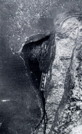
Reference Vivian and BocquetVivian and Bocquet (1973) have shown that large natural cavities and even crevasses are found at the bottom of Glacier d’Argentière. No such crevasses were found at Bondhusbreen and only small natural ice caves were occasionally observed behind steep rock knobs. Their volumes were usually less than 10 l. We never found water in these cavities, but sometimes we could observe the formation of ice spicules (Fig. 9).
Natural small cavity behind a bedrock knob. Ice needles were forming within this cavity which was completely dry. A compass serves as a scale. The general ice movement is towards the camera.

The basal ice layer
Investigations made at Glacier d’Argentière have shown that the ice at the bottom of the glacier is different from the rest of the glacier. Reference Vivian and BocquetVivian and Bocquet (1973) have proposed the name basal ice layer for this ice. At Bondhusbreen, no investigations were made on the chemical and physical properties of this ice but our impression is that it is very similar to the ice described from and photographed at Glacier d’Argentière and Mer de Glace (Reference Vivian and BocquetVivian and Bocquet, 1973, p. 445).
The most typical feature of the basal ice layer at Bondhusbreen was the stratification; layers of debris alternated with layers of cleaner ice. The thickness of the debris-laden layers ranged from 1 to 10 cm, and the number of layers showed variations from place to place. The strata were usually conformable with the bedrock topography and they were found up to about 1.5 m above the ice/bedrock interface. In some places, certain debris layers containing very fine material seemed to form sliding planes. The ice between debris layers was sometimes rather clean and sometimes contained gravel and sand. The lower 10–15 cm of the glacier ice was, in general, relatively clean.
In addition to the pronounced layers, several discontinuous layers or lenses were found. They contained fine material and single rocks up to 0.5 m3 but almost no such material was found above 2 m from the glacier bottom.
Debris-laden ice, including the abovementioned layers, was found everywhere under the glacier, except in an area where water was apparently draining more or less all the year. At this place (intake shaft (c) on Figure 7), the ice was quite clean and blue, and no material could be seen in the ice. This may be explained by the fact that water from Holmavatn lake drains here during most of the year, and thus a channel is kept free from material by simple water transport. Furthermore, because the water stream causes ice melt along this channel, a steady inflow of clean ice can take place from the clean parts of the glacier above.
In the artificial ice tunnels, we usually had no problem with cracking ice, except in the clean ice near the intake shaft (c). Here we frequently observed a very noisy cracking. All the cracks had a direction perpendicular to the tunnel, and during periods of about 15 min the ice walls were made completely white with numerous cracks, and then the situation stabilized again.
Water pockets
Reference Vivian and BocquetVivian and Bocquet (1973) reported that most of the water unconnected with the hydrological system at the base of Glacier d’Argentière was represented by water down-stream of blocks of rocks dragged by the glacier. This type of water pocket has been observed only once at Bondhusbreen. In general, we found no water pockets at all, except in a steep area near the middle of the glacier. The bedrock gradient here is more than 50° but only about 30 m higher up the bedrock is almost flat. The observed water pockets were fairly small, in general less than 0.15 m3, and their number rapidly decreased with increasing size. Most of these small water pockets contained rounded pebbles and gravel (< 1 cm in diameter) and this may indicate that they were formed close to the bottom of the glacier.
No large water pockets were ever found in Bondhusbreen but in one case it was observed that a water pocket drained near an ice tunnel, although the water did not enter the tunnel itself. Based on the noise, it was estimated that the total water volume must have been in the order of 2–4 m3. This event occurred under the south-western part of the glacier (near intake (a) on Figure 7).
Subglacial rock surface
The engineering activities under the glacier proved to be fairly difficult in some places because there was no clear-cut junction between bedrock and ice. A transition zone consisting of compacted, highly fractured rock was observed in some of the shafts when they were approaching the ice. The maximum thickness of this zone was found in the south-western depression (marked (a) on Figure 7). We do not know whether this transition zone extends to larger areas under the glacier, or whether it is concentrated in areas near the depressions. Near the north-eastern intake shaft (marked (c) on Figure 7), where Holmavatn lake drains, an approximately 10 m wide area had no loose material at the bottom and the ice contained no material whatsoever, and no such transition zone was observed here. Observations in the various ice caves revealed a well-polished bedrock but it was more uneven and broken than the bedrock at present found in front of the glacier. The leeward side was often covered by a layer of “brown skin”, particularly near the depressions. So-called “plastic forms” (P-forms; see Reference Andersen and SollidAndersen and Sollid, 1971, p. 11–12) were found occasionally. They were found in small areas but they were never so well developed as normally seen near the tongues of glaciers. The in-situ formation of striae could be seen at several places where rocks and boulders were forced along the bedrock surface.
Subglacial till deposits
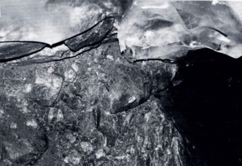
Morainic material could be found almost everywhere beneath the glacier. The thickness of the till layer was in the order of 0.2–1 m. The finest fractions seemed to be absent in this layer of “bottom moraine”, whereas all coarser fractions from coarse silt up to rocks 1–2 m3 in size were present. The material in the bottom moraine was more or less rounded (Fig. 10). Close to the depression it tended to be more rounded than in the areas between them, where it was more sharp-edged in some places. It could often be seen that some rocks were in the process of being over-ridden by others (Fig. 11). Sometimes the surface layers of large rocks were peeled off, possibly by pressure release when the tunnel was melted at the base of the glacier.
Bottom moraine near the intake shafts at (c) (cf. Fig. 7). The material is well comp acted.

A rock is being crushed by glacier movement near (c) (on Fig. 7).

Large rocks, more than 1 m3, were found in several places and smaller rocks, 0.1-0.2 m3, were very frequent. The large rocks and boulders usually showed an irregular surface, but their edges were mostly slightly rounded. It seems that the glacier cannot pick up and transport large rocks and boulders within the ice but rather drags them along the bottom. At Bondhusbreen all the observed rocks larger than 0.5 m3 were resting on the bedrock or on the bottom till layer; they were not entirely embedded in the ice.
Areas between rocks were in general completely filled by ice and all observed till layers were very compact and seemed to be “frozen”, i.e. interstitial ice was apparently present everywhere.
Hydrology
Introduction
The subglacial water intakes are situated beneath 150–170 m of ice where the glacier surface is between 1050 and 1100 m a.s.l., i.e. just above the main ice fall (Fig. 2). The slope of the ice surface here is about 15°, whereas the slope of the subglacial bedrock is about 30° near the intake shaft (a) and about 50° at shafts (b) and (c) (Fig. 7).
Holmavatn (1134 m a.s.l.) is situated near to the north-eastern side of the glacier with an outlet draining into the glacier more or less throughout the year. The distance from Holmavatn to the intake shaft (c) is about 450 m and the mean slope is 28°.
Both the hot-point drillings from the glacier surface and the rock drillings from the tunnel beneath the glacier indicated that the bedrock topography has three major furrows (small valleys) where one could expect subglacial streams. Because of technical problems, the shafts were originally directed towards only two of these depressions ((a) and (b) on Figure 7). The westernmost of these (intake (a)) seemed to be the deepest and most important. Melt water did drain in both of the two “valleys” but the amount captured in the shafts showed great variations. The shafts at (b) gave water during the first part of the ablation season and became dry for the rest of the summer, whereas the other depression (a) gave water during most of the summer but usually not more than 1 m3s–1.
From the horizontal bedrock tunnel, a series of new holes was drilled more or less vertically up to the glacier. Water under high pressure was then located only 5–10 m from the intake shaft (b) (Fig. 7). No measurements were made of the water pressure but it seemed to be highest in the evening after days of high ablation.
Tracer experiments
Several tracer experiments were made to locate the water which almost continuously drains from Holmavatn lake. Salt solutions were injected at the outlet of the lake and repeated electrical conductivity measurements were undertaken in various bore holes in the tunnel roof. The results made it possible to locate the subglacial stream which carried water from the lake. The mean speed of the water from Holmavatn lake to point (c) in the tunnel was almost 0.7 m s–1 along a mean slope of 28°. From Holmavatn lake to a point just outside the glacier snout the mean speed was about 0.75 m s–1 along a slope of 22°. It should be noted that the calculations of these angles is based on a theoretical drainage along the shortest possible distance from the lake to the observation point.
Similar investigations were made in small creeks and streams draining into the glacier from the south-western valley slope. The results indicated that this water quickly found its way to the bottom of the glacier and appeared in intake (a) within 15–30 min. This indicates an average water speed between 0.12 and 0.47 m s–1 on slopes ranging from 35° to 70°.
All these experiments were made in September when water discharge was in general relatively low.
Observed drainage in the tunnel
Some water had drained through the vertical shafts since the summer of 1974, and an automatic water-level recorder was installed to monitor the amount of collected and diverted water. However, the records were unreliable during the first years.
The existing records indicate that the discharge before 1978 was, in general, less than 1 m3 s–1. According to glacier ablation measurements, this was only about 15% of the total water available. Only during shorter periods, mainly no longer than a couple of days, the water discharge rose as high as 3–4 m3 s–1. This usually happened at the end of June or at the beginning of July. The records show a quick rise, closely connected with increasing glacier melting, and a quick decrease. This quick decrease is not related to glacier melting, as the glacier melt maximum seems to follow several hours or even days later.
During the period 12–18 June 1976 a number of unexplained periodic oscillations in water discharge (Fig. 12) were recorded. During these 6 days the discharge ranged from 0.15 to 0.80 m3s–1, within periods of 1–2 h. The glacier ablation decreased during these days but it is not known whether the variations in discharge originated from a smaller or larger part of the glacier, and the reason for the oscillations is also unknown.
Unexplained oscillations in water discharge were recorded at the outlet of the sedimentation chamber during a short period in June 1976.

Since the new intake shafts in the north-eastern bedrock furrow (marked (c) in Figure 7) were completed during the spring of 1978, the situation has changed completely. Even before any melting had begun on the glacier, a discharge of about 100 l s–1 was observed. It is believed that most of this water originated from Holmavatn lake.
When the glacier ablation began in the middle of May, a sudden increase in water flow occurred, and a steady discharge of about 5 m3 s–1 was reached within a few days. During the summer the water discharge in the tunnel system ranged between 2 and 10 m3s–1. The total amount of water draining from the glacier into the diverting system proved to be as high as 50 x 106 m3. This is more than 90% of the theoretical amount of water available at the intake level, and nearly all this water came through the new intake shaft ((c) in Figure 7). The other shafts were completely dry and plugged by ice during the entire summer, but still some water drained from bore holes near shaft (b).
Conclusion
Reference RöthlisbergerRöthlisberger (1972) has stated: “In large valley glaciers it is likely that a major channel, the bottom conduit, runs along the thalweg, but two additional main streams may exist at lesser depth closer to both glacier margins”.
From the investigations made at Bondhusbreen, we can now draw the following preliminary conclusions:
-
i. Most of the water seems to drain in a main subglacial channel in the lower part of the subglacial valley.
-
ii. The existence of a draining channel along the north-eastern side of the valley, kept permanently open by the water from Holmavatn, seems to facilitate the drainage of water from large parts of the glacier.
-
iii. Only small areas of the glacier above the intake altitude drained outside the north-eastern channel (intake (c)) in 1978. However, this stability did not seem to be representative of the previous years when large water volumes were captured through the other intakes ((a) and (b)) during certain periods.
-
iv. At the intake level, no additional main streams seem to exist at smaller depths closer to the glacier margins.
-
v. When the draining channels have been established, they also seem to be kept open at fairly low water discharges.
Acknowledgements
The glaciological and hydrological studies mentioned in this paper were made in close co-operation with the State Power Board within the Norwegian Water Resources and Electricity Board.
Some of the studies were made to assist the engineers in their decisions during the planning stage of the power station in Mauranger, whereas other investigations were undertaken during the construction work.
The authors are most indebted to the chief engineers, Mr H. Døhlen and Mr S. Lunde, who understood the interest for glaciological studies in addition to the pure technical measurements required for the completion of their construction tasks. They gave us all possible assistance in the field; in addition, the Building Division and the Western District within the State Power Board and the Hydrology Division supported our work in general.
The Department of Physical Geography, University of Stockholm, also assisted during various stages of the work, and some of the illustrations were drawn at that Department. We therefore extend our thanks to these institutions; their help was invaluable in the completion of our studies.
Discussion
R. Brepson: Have you observed undulations in the bands of dirty ice? And in this case, do these undulations differ from the profile of the base?
G. Østrem: The bands of dirty ice are undulating and seem to reflect the form of the subglacial topography.
B. Hallet: Were the very large boulders you found in the tunnel carried there by water?
Østrem: Yes. In fact this caused concern amongst the engineers.
S. M. Hodge: Did you measure the surface motion before and after removing water from the glacier bed? If so, did it change significantly?
Østrem: The velocity measurements were made at the surface just above the water intakes. We have no indication of any change in velocity after capturing the water.
Hodge: Did you observe any interstitial ice or water in the “till” underlying the basal ice that might correspond to the sub-sole drift observed under Blue Glacier by Kamb and others?
Østrem: Interstitial ice was often observed in the basal “till”.
Hallet: Although you observed ice in the basal debris layer, one must be careful to note that it is quite possible for ice to invade rapidly the debris once the pressure is released by the melting of your tunnel. Directly after melting, did you ever observe debris-free ice at the glacier base?
Østrem: The interstitial ice in the debris layers was often observed only a few minutes after the pressure had been released by making the tunnel. Directly after melting, debris-free ice at the glacier base was observed only at very few places. Debris-free ice at the base seems to be present only where water has recently been draining.