I. INTRODUCTION
With the explosive development of wireless communications and computer technologies nowadays, smart portable devices such as phones, laptops, and tablets, have almost become essential parts in our daily lives. For such kind of products, besides the basic characteristics such as compact size, attractive appearance, and easy operation, users put more focus on whether it could support multiple wireless communication protocol standards such as global positioning system (GPS), wireless local area network (WLAN), worldwide interoperability for microwave access (WiMAX), and so forth. Therefore, a multiband antenna that could well support various communication standards is highly desired and it brings new challenges and opportunities for antenna designers.
Printed planar antennas such as planar monopole antennas and microstrip-fed patch (or slot) antennas are widely adopted for multiband antenna designs in recent literatures [Reference Sun, Zeng, Yang and Li1–Reference Zarrabi, Mansouri, Ahmadian, Rahimi and Kuhestani8] due to the merits of simple structure, low cost, and easy integration. There are several design methodologies usually employed to achieve multiband characteristic such as using embedded slots [Reference Sun, Zeng, Yang and Li1–Reference Jalali, Ahamdi and Emadian3], adding parasitic radiating branches [Reference Liu, Wu and Tseng4–Reference Parkash and Khanna6], loading artificial structures such as split ring resonators or complementary split ring resonators [Reference Rajeshkumar and Raghavan7, Reference Zarrabi, Mansouri, Ahmadian, Rahimi and Kuhestani8], etc. The majority of multiband antennas reported [Reference Sun, Zeng, Yang and Li1–Reference Zarrabi, Mansouri, Ahmadian, Rahimi and Kuhestani8] till now exhibit a dual-band or triple-band feature. In order to provide compatibility with more communication standards in a single device, researchers are seeking a more competitive approach, such as quad-band antenna. However, to our best knowledge, only a small number of quad-band antennas are indicated in the reported literatures [Reference Xiong, Gao and Tang9–Reference Karthikeya14]. The planar antenna in [Reference Xiong, Gao and Tang9] is composed of three stubs extending from a modified wide-slot on the ground plane. The antenna in [Reference Cao, Cheung and Yuk10] presents a paperclip-like structure consisting of an inverted-L-shaped strip and a C-shaped meander branch. In [Reference Yang, Liu and Wu11], the quad frequency bands are excited by a wide slot along with a T-shaped feed patch, one inverted T-shaped, and two E-shaped stubs. Although these three antennas could fulfill the communication demands of GPS, WLAN and WiMAX, they all suffer the disadvantage of big antenna dimensions. In [Reference Avila and Marrero12], the antenna consists of several slots of different geometries which are responsible for four resonating bands. In addition, the quad-band characteristic can also be created by a series of similar fractal structures with different size, such as trapezoidal structure in [Reference Rajeshkumar and Raghavan13] and Koch snowflake structure in [Reference Karthikeya14]. These antennas achieve a relatively compact size of about 30 × 30 mm2, but they fail to cover 1.5 GHz frequency band to satisfy the GPS communication requirement. Their structures are comparatively complex and vulnerable to manufacture deviation. Therefore, achieving sufficient multiband and broadband for GPS/WLAN/WiMAX systems with small size and simple structure still remains a big challenge in the research field of multiband antenna.
This paper presents a novel asymmetric coplanar strip (ACS)-fed F-shaped quad-band monopole antenna for GPS/WLAN/WiMAX systems. Four distinct frequency bands are generated by etching a Γ-shaped slot on the top portion of the monopole. The overall size of the ACS-fed antenna can be reduced by nearly half compared to a coplanar waveguide (CPW)-fed antenna, making it more suitable for miniaturized electronic devices. The experimental and measured results indicate that the proposed antenna could cover the 1.575-GHz GPS (1.57–1.59 GHz), 2.4/5.2/5.8-GHz WLAN (2.4–2.484, 5.15–5.35, and 5.725–5.825 GHz) and 2.5/3.5/5.5-GHz WiMAX (2.50–2.69, 3.30–3.70, and 5.25–5.85 GHz) bandwidths with a compact size of 40 × 20 mm2 and quite a simple structure, which brings much convenience to the antenna manufacture.
II. ANTENNA DESIGN
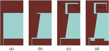
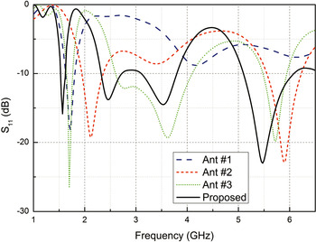
The design process can be divided into four steps with different antenna configurations which are denoted in Fig. 1 as Ant #1, Ant #2, Ant #3, and the proposed antenna, respectively. These antennas are all printed on low-cost FR4 substrates (ε r = 4.3, tan δ = 0.02) with the same dimensions of 40 × 20 × 1.6 mm3 and the simulated results of S 11 carried out by CST Microwave Studio are plotted in Fig. 2.
Design evolution of the proposed ACS-fed F-shaped monopole antenna.

Simulated return losses.

Firstly, the antenna design starts with a traditional ACS-fed inverted L-shaped monopole antenna, which is composed of an inverted L-shaped monopole and a partial ground plane on one side of the substrate as depicted in Fig. 1(a). As shown in Fig. 2, for Ant #1, only one narrow band (S 11 < −10 dB) is generated around 1.70 GHz, which is determined by the total length of the inverted L-shaped monopole.
Then an ACS-fed F-shaped monopole antenna, Ant #2, is designed by adding a trapezoidal strip as presented in Fig. 1(b). Two separate resonant modes can be excited by two different radiating branches of the F-shaped radiator, which lead to a dual-frequency operation at about 2.10 and 5.90 GHz as shown in Fig. 2.
To further increase the number of resonances, and hence meet the bandwidth requirement of GPS/WLAN/WiMAX systems, an open-ended L-shaped slot is embedded on the top portion of the F-shaped monopole which is denoted as Ant #3 in Fig. 1(c). Here, the vertical and horizontal branches of the L-shaped slot are represented by S 1 and S 2 respectively. The introducing of the open-ended L-shaped slot produces an extra broad operating band ranging from 2.60 to 4.10 GHz, which is merged by a pair of sub-bands with two resonances at about 2.75 and 3.60 GHz as indicated in Fig. 2. Consequently, Ant #3 achieves a triple-band characteristic with the −10 dB impedance bandwidth covering 1.65–1.75, 2.60–4.10, and 5.48–5.95 GHz. Although the operating band of Ant #3 could not satisfy the expected communication demand, it provides a promising design basis.
It is not difficult to find that the four resonant frequencies of Ant #3 (1.70, 2.75, 3.60, and 5.75 GHz) are higher than the specified center frequencies of the GPS (1.57–1.59 GHz), WLAN (2.4–2.485, 5.15–5.25, and 5.725–5.825 GHz), and WiMAX (2.50–2.69, 3.30–3.70, and 5.28–5.85 GHz) systems. The simplest solution that could be applied to this design is to further increase the effective electric length of the current path. Then an additional narrow vertical slot (S 3) is added at the end of the L-shaped slot as depicted in Fig. 1(d). Meanwhile, two small rectangular slots are etched on the ground plane for better impedance matching, which presents the final version of the proposed novel ACS-fed F-shaped quad-band monopole antenna. The simulated result of S 11 shown in Fig. 2 suggests that the proposed antenna has achieved a broad operating bandwidth of 60 MHz (1.55–1.61 GHz), 360 MHz (2.34–2.70 GHz), 580 MHz (3.20–3.78 GHz), and 970 MHz (5.13–6.10 GHz), fully covering the GPS, 2.4/5.2/5.8-GHz WLAN and 2.5/3.5/5.5-GHz WiMAX applications.
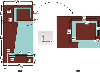
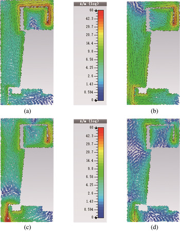
After the basic structure of the proposed antenna is established as shown in Fig. 3, how to determine the geometrical detail is becoming the next key design point. So the working mechanism of the proposed antenna is further investigated by means of surface current distribution analysis at the center frequencies of GPS, WLAN, and WiMAX systems as shown in Fig. 4. The surface current distribution at 1.575 GHz shown in Fig. 4(a) indicates that the resonance is mainly generated by the Γ-shaped slot, which operates as a monopole antenna. While for the three high-frequency bands, there are two effective surface current paths as shown in Fig. 4(b)–(d). One exists on the right part of Γ-shaped slot, and the other exists on the left part of the slot and the trapezoidal strip. In this case, the antenna operates as a folded dipole-like antenna. It can be obviously seen that the Γ-shaped slot plays a very important role in generating the four resonance bands and the determining of its geometrical parameters can be discussed in detail combining the surface current.
Antenna geometry: (a) top view, (b) detailed configuration of the Γ-shaped slot.

Simulated current distributions at: (a) 1.575 GHz, (b) 2.5 GHz, (c) 3.5 GHz, and (d) 5.5 GHz.

The surface current at 1.575 GHz shown in Fig. 4(a) mainly concentrates on the Γ-shaped slot and the total length of the slot can be basically confirmed according to a rough calculation:
 $$L_\Gamma = L_{S1} + L_{S2} + L_{S3} \approx \displaystyle{c \over {4 \times 1.575 \times {10}^9 \times \sqrt {\varepsilon _e}}} = 29.5.$$
L
Γ is the total length of the Γ-shaped slot, L
S1–L
S3 represent the lengths of slots S
1–S
3, respectively, c is the speed of light in free space, and ε
e
is the effective dielectric constant usually given by
 $\varepsilon _e \approx \displaystyle{{\varepsilon _r + 1} \over 2}$
.
While the proposed antenna operates as a folded dipole-like antenna at the three higher resonances, two different current paths exist as shown in Fig. 4(b)–(d). But in order to determine the optimum geometrical parameters of Γ-shaped slot more easily, here we only place emphasis on the current path concentrating on the right part of the Γ-shaped slot for simplicity. To be specific, the current distribution is mainly focused on S 2 and S 3 for the resonance at 2.5 GHz as plotted in Fig. 4(b) and the sum of L S2 + L S3 is approximately equal to a quarter wavelength at 2.5 GHz, which can be calculated by:
 $$L_{S2} + L_{S3} \approx \displaystyle{c \over 4 \times 2.5 \times 10^9 \times \sqrt{\varepsilon _e}} = 18.5 \; {\rm mm}. $$
For 3.5 GHz as shown in Fig. 4(c), the sum of L S2/2 + L S3 is about a quarter wavelength at 3.5 GHz and can be expressed by:
 $$L_{S2}/2 + L_{S3} \approx \displaystyle{c \over {4 \times 3.5 \times {10}^9 \times \sqrt {\varepsilon _e}}} = 13.2\,{\rm mm}{\rm.} $$
For the resonance at 5.5 GHz as shown in Fig. 4(d), the surface current mainly distributes around S 3 and its length can be determined by:
 $$L_{S3} \approx \displaystyle{c \over {4 \times 5.5 \times {10}^9 \times \sqrt {\varepsilon _e}}} = 8.4\,{\rm mm}{\rm.} $$
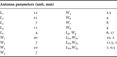
In conclusion, the parameters of the Γ-shaped slot can be initially set as follows: L S1 = 10 mm, L S2 = 11 mm, and L S3 = 8 mm. Since that the influence of the width of the Γ-shaped slot has not been considered in the above calculations, the final determination of design parameters might be slightly adjusted depending on the result of global optimization process. After several simulations and adjustments, the optimal design parameters of the F-shaped ACS-fed monopole antenna are decided and listed in Table 1. Since each multiband antenna consists of many geometrical parameters, especially for those with complicated structure, the determining of these parameters are sure to go through a series of intricate parametric study and simulation that would increase its design difficulty and complexity. In this design, certain design guides established by equations (1)–(4) offer some calculation foundation to simplify this step a lot. The proposed antenna is simply composed of a novel F-shaped monopole with an open-ended Γ-shaped slot and a partial ground plane with a compact size of only 40 × 20× 1.6 mm3, which is acceptable for most portable devices.
Optimal design parameters.

III. SIMULATION AND MEASURED RESULTS
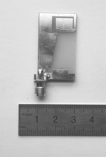
A prototype of the proposed ACS-fed F-shaped quad-band monopole is presented in Fig. 5. The impedance properties, radiation patterns, and gains are simulated by CST Microwave Studio and then verified experimentally.
Photograph of the fabricated antenna.

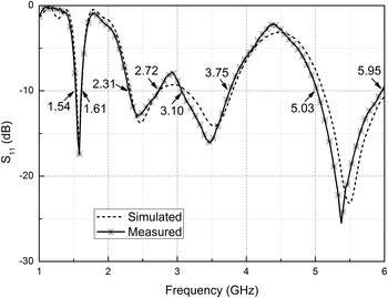
The simulated and measured return losses of the proposed antenna are shown in Fig. 6. It is evident that four distinct resonant modes are successfully excited at about 1.58, 2.45, 3.48, and 5.38 GHz. The measured result exhibits a wide −10 dB operating bandwidth of 70 MHz (1.54–1.61 GHz), 410 MHz (2.31–2.72 GHz), 650 MHz (3.10–3.75 GHz), and 920 MHz (5.03–5.95 GHz). It can completely cover the desired 1.575-GHz GPS, 2.4/5.2/5.8-GHz WLAN, and 2.5/3.5/5.5-GHz WiMAX operating bandwidths. The measured result agrees well with the simulated one, and deviations may result from fabrication imperfection.
Simulated and measured return losses.

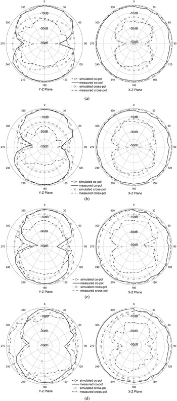
The simulated and measured radiation patterns of the proposed antenna in the xz- and yz-planes at center frequencies of the operating bands are shown in Fig. 7. For these frequencies, the radiation patterns exhibit acceptable stability with good omni-directional radiation patterns in xz-planes and the measured and simulated results match reasonably well. Since the major radiating element Γ-shaped slot contains vertical and horizontal components, thus a considerable amount of cross-polarization is found with the increased frequency, especially at 3.5 and 5.5 GHz. Nevertheless, the proposed antenna is still desirable for many applications such as indoor wireless communications where lots of multipath scattering exists and the polarization purity is not a major issue.
Simulated and measured radiation patterns at: (a) 1.575 GHz, (b) 2.5 GHz, (c) 3.5 GHz, and (d) 5.5 GHz.

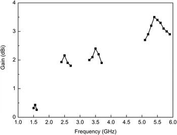
The measured gains of the proposed antenna are shown in Fig. 8. For the 1.575-GHz GPS band, the antenna gain is varied from 0.26 to 0.43 dBi. The antenna gains for 2.4/5.2/5.8-GHz WLAN bands are varied from 1.93 to 2.16 dBi, 2.72 to 3.20 dBi, and 3.05 to 3.12 dBi, respectively. Over 2.5/3.5/5.5-GHz WiMAX bands, the antenna gains are about 1.80–2.16 dBi, 1.90–2.40 dBi, and 2.95–3.50 dBi. Although the antenna gain at GPS band is not high mainly due to dimensional limit, it is still suitable for most miniaturized wireless devices.
Measured antenna gains.

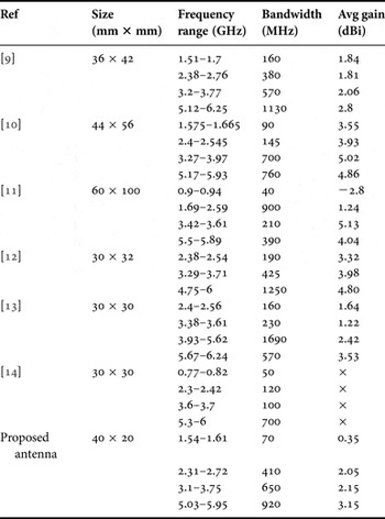
In order to further evaluate the performance of the proposed novel ACS-fed F-shaped antenna, a comparison in terms of antenna size, frequency band, and corresponding bandwidth, gain with other quad-band antennas in the literatures [Reference Xiong, Gao and Tang9–Reference Karthikeya14] recently published is given in Table 2. Here, × denotes unmentioned performance figure in the paper and gain refers to the average gain of relative frequency band. We can see obviously from this table that the proposed antenna achieves similar good communication characteristics while maintaining an extraordinarily compact size, only occupying 53, 33, and 13% area of those quad-band antennas in [Reference Xiong, Gao and Tang9–Reference Yang, Liu and Wu11], respectively. Compared with antennas in [Reference Avila and Marrero12–Reference Karthikeya14], the proposed antenna could cover the specified frequency band of GPS application, which is important for modern wireless devices, such as mobile phones and handheld electronic gadgets, while others cannot. Therefore, the proposed ACS-fed F-shaped quad-band antenna offers a competitive antenna approach for 1.575-GHz GPS, 2.4/5.2/5.8-GHz WLAN, and 2.5/3.5/5.5-GHz WiMAX applications considering its simple structure, compact size, sufficient bandwidth, and satisfactory gain.
Performance comparison with other quad-band antennas.

IV. CONCLUSION
A novel ACS-fed F-shaped quad-band monopole antenna for GPS/WLAN/WiMAX applications is presented in this paper. A modified F-shaped monopole, with a novel Γ-shaped slot etching on the top portion, successfully excites four different resonant frequencies at 1.58, 2.45, 3.48, and 5.38 GHz. It could fully cover the 1.575-GHz GPS, 2.4/5.2/5.8-GHz WLAN, and 2.5/3.5/5.5-GHz WiMAX applications with satisfactory gains and radiation patterns. The antenna also holds the advantage of a simple structure and a relatively compact size of 40 × 20 mm2. Therefore, the proposed quad-band antenna is well suited for portable devices to support GPS/WLAN/WiMAX multiband applications.
ACKNOWLEDGEMENTS
The authors would like thank Professor K. S. Chen from the Electromagnetics Academy, Zhejiang University, and Doctor C. Z. Hua from the School of Electrical Engineering and Computer Science, Ningbo University, for many useful discussions.
 Wang Ren received the Ph.D. degree in Electrical Engineering from Zhejiang University, Hangzhou, China in 2008. He joined Zhejiang Gongshang University in 2008 and is currently working there as an Assistant Professor. His research interests include antenna design and microwave circuit.
 Shu-Wei Hu received his B.E. degree in Electronic Engineering from Anqing Normal University, Anqing, China in 2015. He is currently studying for the M.S. degree at the Zhejiang Gongshang University and his research interests include wideband and multiband antenna design.
 Cheng Jiang received her B.E. degree in Electronic Engineering from Xiamen University TanKah Kee College, Zhangzhou, China in 2014. She is currently studying for the M.S. degree at the Zhejiang Gongshang University and her research interests include wideband and multiband antenna design.