I. INTRODUCTION
Electro-deposited coatings are widely used in automotive and aerospace industries due to advantages, such as good anti-corrosion performance, applicability to various substrate materials, low deposition cost, and precise control.Reference Alkire and Kolb1,Reference Fettis2 Additionally, electro-deposited coatings maintain anti-friction properties, thereby being often applied to tribo-components. For instance, epoxy-based cathodic electro-deposited coatings are applied to automotive seat slide tracks.Reference Kim3 A steady-state friction coefficient between the coating and a bearing steel ball was found to be about 0.3 under dry conditions. Other electro-deposited coatings were developed and their tribological properties were evaluated.Reference Redlich, Gorodnev, Feldman, Kaplan-Ashiri, Tenne, Fleischer, Genut and Feuerstein4–Reference Ray, Bose, Chiou, Tsai, Jan, Kumar, Pong, DasGupta, Fanchini and Tagliaferro6 An electro-deposited Ni coating was developed with inorganic fullerene-like nano-spheres of tungsten disulphide.Reference Redlich, Gorodnev, Feldman, Kaplan-Ashiri, Tenne, Fleischer, Genut and Feuerstein4 An electro-deposited Ni coating was found to reduce the frictional force of archwires in orthodontic applications. Electro-deposition of diamond-like carbon films on nickel and silicon substrates was studied.Reference Chen, Pingsuthiwong and Golden5,Reference Ray, Bose, Chiou, Tsai, Jan, Kumar, Pong, DasGupta, Fanchini and Tagliaferro6 Effective deposition processes were described for synthesizing diamond-like carbon films from organic liquid and from a solution of acetylene in liquid ammonia. Recently, pulsed electro-deposited nickel–tungsten coatings were developed from a citrate bath.Reference Wasekar and Sundararajan7 It was identified that the wear rate of electro-deposited nickel–tungsten coatings was lower than those of conventional hard chrome coatings under dry conditions. Tin coatings were electrodeposited from sulfonic acid electrolytes, and the tribological behavior was studied.Reference Bengoa, Tuckart, Zabala, Prieto and Egli8 A super-hydrophobic composite coating was electrodeposited with a nano-crystalline metal matrix.Reference Iacovetta, Tam and Erb9 Microhardness of an electro-deposited composite coating was evaluated with various saccharin concentrations in an electrolyte.
A ball-on-flat or cylinder-on-flat contact geometry is typically used for automotive seat-adjusting slide rails. A metallic ball is placed between two rails for the purpose of adjusting a seat. The ball is permitted to roll or slide on the rails made of cold-rolled high strength steel. Thus, sliding wear, fretting wear, and contact fatigue occur at the surface of the rail. These contact damages are determined with the relative displacement between the ball and the coated rail. If a seat remains fixed, auto-engine vibration or external force leads to a small-amplitude oscillatory movement between the ball and the rail at the microscale. That is, either partial slip or gross slip is observed in the contact zone. While the seat is adjusted, the movement of the seat leads to tractive rolling or sliding of the ball on the coated rail. Sliding of the ball brings about abrasive wear of an electro-deposited coating within a reciprocal sliding regime, and tractive rolling results in contact fatigue cracks and wear of rails. The transition between the gross slip and reciprocal sliding regimes was identified with various criteria, such as slip ratio, energy ratio, and slip index.Reference Sandstrom, Sridharanan and Conrad10–Reference Varenberg, Etsion and Halperin12 Slip ratio was defined as the ratio of the actual sliding distance to the imposed displacement.Reference Sandstrom, Sridharanan and Conrad10 A slip ratio of 0.26 indicated the transition between partial and gross slip regimes. The energy ratio was proposed to normalize energy evolution and define transition criterion.Reference Fouvry, Kapsa and Vincent11 It was proposed that the transition between partial and gross slip regimes was found at an energy ratio of 0.2. The slip index, expressed with displacement amplitude, stiffness, and normal force, was introduced to describe the transition between gross slip and reciprocal sliding.Reference Varenberg, Etsion and Halperin12 It was identified that the gross slip was observed when the slip index or slip ratio was less than 10 or 0.95, respectively.
Contact damage which arose from reciprocating motion is often evaluated with a simplistic test equipment including measurements of the kinetic friction coefficient and wear rate.Reference Bhushan13–Reference Korsunsky, Torosyan and Kim15 The practical measurement of the kinetic friction coefficient is carried out with a pin (or ball)-on-disk test apparatus, and ball-on-flat plate test apparatus.Reference Bhushan13,Reference Williams16 In a conventional pin-on-disk test apparatus, a round-tip pin or a ball is gripped in a cantilever-type beam. A disk is then rotated at a given rotational speed. In a typical ball-on-flat plate test apparatus, a ball is linearly slid on a flat plate. Alternatively, a flat specimen is moved against a fixed ball with a predefined displacement amplitude.
The measurement of wear volume is used with two contacting materials or a softer material. Numerous methods for material loss measurement are used.Reference Bhushan13 Conventional methods include topographical measurement by using an optical microscope, scanning electron microscope (SEM), atomic force microscopy (AFM), or stylus profilometry. The wear rate is determined via the wear volume measurement with worn specimens interrupted at different numbers of cycles. Meanwhile, the online measurement of wear volume is useful for identifying wear resistance of multi-layered solid lubricant coatings. For instance, fretting may bring about thermal expansion of a metallic layer in a composite solid lubricant coating. Nevertheless, little is found on the online wear measurement of a solid lubricant coating.
In this study, a ball-on-flat plate tribometer was developed, measuring tangential and normal displacements of a ball during a test. An epoxy-based electro-deposited coating was subjected to fretting and reciprocal sliding under the condition similar to those found in automotive seat tracks. The kinetic friction coefficient was determined, along with displacements of a ball. A correlation was sought between wear volume of a coating and the normal displacement of a ball.
II. EXPERIMENTAL DETAILS
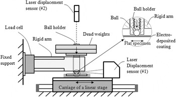
Figure 1 shows a developed testing machine for fretting and linear reciprocal sliding. Ball-on-flat plate contact was generated; a flat specimen was mounted on the carriage of a linear stage (LS-110, PImiCos GmbH, Eschbach, Germany). The reciprocation of the carriage was imposed in a sine wave. In this apparatus, a ball was fixed in a ball holder. The ball holder was allowed to move vertically in a rigid arm that was connected to a load cell (Interface, Inc., Atlanta, Georgia). Normal force between the ball and a flat specimen was induced by dead weights. The relative displacement between the ball holder and the flat specimen was measured with a laser displacement sensor mounted on the carriage. A tangential force and a relative displacement were recorded and then a force–displacement loop was plotted over a cycle. The other laser displacement sensor was located above the ball holder to measure the normal displacement of the ball during a test. Laser displacement sensors (LK-081, Keyence Corp., Itasca, Illinois) used for the test maintained a resolution of 3 µm and a linearity of ±0.1%.
Schematic illustration of the test apparatus.

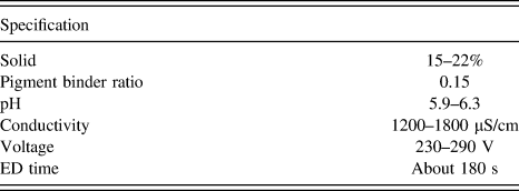
A cold-rolled high strength steel (SPFC 780 DP, provided by DAS Corp., Gyeongju, Gyeongbuk, Republic of Korea) sheet was used as the substrate of a coated specimen. The specimen had a diameter of 20 cm and a thickness of 2.6 mm. The counterpart of the flat specimen was a high carbon chrome steel (AISI 52100, provided by NSK-AKS Inc., Clarinda, Iowa) ball with a diameter of 5 mm and an arithmetic average surface roughness of about 0.025 µm. The steel ball contains 0.95–1.10 wt% C, 0.15–0.35 wt% Si, 0.05 wt% Mn, 0.025 wt% P, 0.025 wt% S, and 1.3–1.6 wt% Cr. Mechanical properties of the ball are an elastic modulus of about 200 GPa, Poisson's ratio of 0.3, and a hardness of 700 kg/mm2. An epoxy-based electro-deposited coating was applied onto the substrate with a thickness of 0.02–0.04 mm (note that a difference of 0.02 mm in thickness might affect the duration of steady-state sliding and the durability of an electro-deposited coating in a kinetic friction coefficient evolution.). The coating included an epoxy resin with a crosslinker of blocked aromatic isocyanates and with a metal catalyst. Table I shows the conditions of electro-deposition.
Conditions of electro-deposition (ED) on steel.

In this study, a normal force of 49 N and a frequency of 1 Hz were applied to the contact between a ball and a flat specimen. The imposed normal force was similar to those found on automotive seat-adjusting slide rails; that is, a loaded seat with 16 balls was assumed to be 80 kgf in weight. To produce fretting (gross slip) and reciprocal sliding, displacement amplitudes of 0.2 and 1.0 mm were selected, respectively. Dry ball-on-flat tests were conducted at room temperature and ambient humidity.
III. RESULTS AND DISCUSSION
Fretting tests with an electro-deposited coating were conducted at a displacement amplitude of 0.2 mm. The tests were interrupted at three different cycles (100th, 500th, and 800th cycles). In the author's earlier study on electro-deposited coatings,Reference Kim3 the evolution of the kinetic friction coefficient was found to be divided into three distinct stages: the running-in period, a steady-state sliding stage, and a final stage of sliding. After the initial running-in period, the friction coefficient was almost steady, since a ball slid on a coating layer. At the final stage of sliding, the friction coefficient dramatically increased up to a critical value. The earlier study was focused on a reciprocal sliding test with a displacement amplitude of 0.5 mm.Reference Kim3 In addition, the analysis of the kinetic friction coefficient was merely used without the measurement of wear volume.
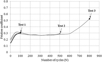
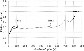
Figure 2 shows the friction coefficient evolution of an electro-deposited coating against a high carbon chrome steel ball at the displacement amplitude of 0.2 mm. The friction coefficient increased up to the 80th or 100th cycle. The friction coefficient remained approximately constant with a friction coefficient of 0.28. Finally, the friction coefficient was found to increase strongly, following a steady-state sliding stage. There was a good agreement between three friction coefficient evolutions.
The evolution of the kinetic friction coefficient between an electro-deposited coating and a high carbon chrome steel ball at the displacement amplitude of 0.2 mm.

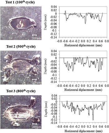
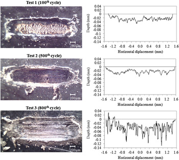
Figure 3 shows worn surfaces and surface profiles after different cycles. Worn surface images were captured by an optical microscope. In the image captured after the 100th cycle, a crater was shown as a result of fretting. It was identified that the fretted contact surface was non-uniform. In the middle of the contact, the substrate was partially observed. The image after the 500th cycle shows that the substrate appeared near contact edges, while some coating was found to remain in the middle of the contact. Large amounts of coating debris were observed near contact edges. From the image, after the 800th cycle, the electro-deposited coating was found to wear off and the substrate was strongly roughened. The increased friction coefficient after the 500th cycle was attributed to the enhanced interlocking between a growing roughening of the substrate and the surface of the ball. Surface profiles of tested specimens were measured by non-contact laser profilometry (Fig. 3). Wear volume was then computed on the basis of measured surface profiles and surface images. That is, wear volume was determined as the actual contact area times the average wear depth.
Worn surface images (250×) and profiles at the displacement amplitude of 0.2 mm.

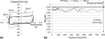
During a fretting test, it is necessary to identify a slip regime. In a partial slip regime, fatigue cracking occurs near contact edges, while in a gross slip regime, wear is observed at contact. Wear rate within a gross slip regime was found to be different from that within a reciprocal sliding regime.Reference Vingsbo and Soderberg17 It is possible to identify a slip regime with the slip ratio. The slip ratio was defined as the ratio of the actual sliding distance to the imposed displacement.Reference Varenberg, Etsion and Halperin12 The actual sliding distance and imposed displacement were determined on a fretting loop as shown in Fig. 4(a). It was observed that fretting loops were quasirectangular. Particularly, the fretting loop after the 800th cycle maintained tangential force peaks near contact edges, resulting from a plunging effect.Reference Fouvry, Duóa and Perruchaut18Figure 4(b) shows the evolution of the slip ratio during a test. The slip ratio remained below 0.95 in three tests, indicating that fretting tests were completed within a gross slip regime.
Identification of a slip regime at the displacement amplitude of 0.2 mm: (a) fretting loops after various cycles and (b) slip ratio values.

To obtain the evolution of the friction coefficient within a reciprocal sliding regime, sliding tests were conducted at a displacement amplitude of 1.0 mm. Sliding tests were terminated at three different cycles (100th, 500th, and 800th cycles). Figure 5 shows the evolution of the friction coefficient at the displacement amplitude of 1.0 mm. The initial value of the friction coefficient was close to 0.15. After the running-in period, the friction coefficient slowly increased. After the 500th cycle, the friction coefficient increased rapidly. The final friction coefficient was 0.47, lower than the coefficient (0.53) found in a gross slip regime. The difference between the final coefficients might be attributed to the variance of the initial coating thickness and the difference of wear mechanisms for reciprocal sliding and gross slip. For identifying the apparent wear mechanism and the influence of the initial coating thickness, further tests need to be conducted.
The evolution of the kinetic friction coefficient between an electro-deposited coating and a high carbon chrome steel ball at the displacement amplitude of 1.0 mm.

Figure 6 shows worn surface images and surface profiles at the displacement amplitude of 1.0 mm. The upper image (test 1) shows that the substrate partially appeared, along with a roughened coating layer. The image captured after the 500th cycle shows that a coating layer still remained in a contact zone. The roughened coating layer seems to be flat by sliding of a ball between 100 and 500 cycles. The lower image (test 3) shows wearing-off of a coating and scratches on the substrate in the direction parallel to the sliding direction. Coating debris particles were observed near contact edges.
Worn surface images (250×) and profiles at the displacement amplitude of 1.0 mm.

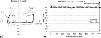
After sliding tests, tangential force–displacement hysteresis loops were determined along with the slip ratio. The loops were rectangular-shaped as shown in Fig. 7(a). The loop after the 800th cycle had tangential force peaks near contact edges. Figure 7(b) shows the evolution of the slip ratio during a test. All slip ratio values during Tests 1 and 3 remained above 0.95, indicating that the tests were completed within a reciprocal sliding regime. Although some slip ratio values for Test 2 were less than 0.95, most slip ratios were above 0.95.
Identification of a slip regime at the displacement amplitude of 1.0 mm: (a) force–displacement loops after various cycles and (b) slip ratio values.

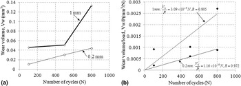
Volume loss of a coated specimen was determined with worn surface images and surface profiles. In this study, volume loss was defined as the actual worn surface area times the average wear depth found in surface profiles. Figure 8(a) shows the volume loss of a coated flat specimen after different cycles. At a displacement amplitude of 0.2 mm, the wear volume increased linearly with respect to the number of cycles. Figure 8(b) shows the specific wear rate coefficient of an electro-deposited coating against a high carbon chrome steel ball. At the displacement amplitude of 0.2 mm, a specific wear rate coefficient was found to be 1.16 × 10⁻⁶. Meanwhile, at the displacement amplitude of 1.0 mm, the specific wear rate coefficient was about 3.09 × 10⁻⁶. To identify accurate specific wear rate coefficient at the displacement of 1.0 mm, additional sliding tests need to be conducted.
Determination of wear on an electro-deposited coating at different displacement amplitudes: (a) wear volume and (b) specific wear rate coefficient.

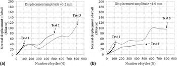
During fretting and reciprocal sliding tests, the displacement of the ball normal to the contact surface was measured by using a laser displacement sensor. The increased normal displacement indicated that the ball moved through a coating layer in the direction normal to the contact surface. The normal displacement of the ball included the elasticity of materials and the wear depth on a coated specimen. Figure 9 shows the change of the normal displacement of a ball during a test. The normal displacement of the ball had a tendency to increase with respect to the number of cycles. In Fig. 9, there were small variances among three tests. Particularly, variances for reciprocal sliding were bigger than those for the gross slip. In Fig. 9(b) the difference of the normal displacement between Tests 2 and 3 was about 20 µm at the 500th cycle. Various reasons could be attributed to the difference, including test-to-test variance, the initial asperity of the ball, the resolution of the displacement sensor (3 µm), and variance of the initial coating thickness (20–40 µm). To use the proposed measurement method, it is necessary to reduce the variance in normal displacement and to assure reproducibility of a test. For identifying more apparent reasons, additional reciprocal sliding tests need to be conducted.
Normal displacement of a ball at the displacement amplitudes of (a) 0.2 mm and (b) 1.0 mm.

Figure 10 shows the relationship between wear volume on a flat specimen and the normal displacement of a ball. Linearity was found between wear volume and the normal displacement of a ball at the displacement amplitudes of 0.2 and 1.0 mm. The linear relationship provides that the normal displacement of a ball can be a useful indicator for monitoring wear in the course of a test.
Wear volume of a coated specimen versus the normal displacement of a ball at different displacement amplitudes.

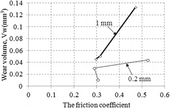
Figure 11 shows the relationship between wear volume and the friction coefficient between an electro-deposited coating and a high carbon chrome steel ball. Particular interest was found in the relationship obtained after the fretting test (0.2 mm in amplitude). Correlation between wear volume and the friction coefficient was not found between 100 and 500 cycles (steady-state sliding stage). At the steady-state sliding stage, predominant contact was made between the ball and the coating layer. Roughening of the coating layer resulting from progressive material loss was not sufficient to increase the friction coefficient. Correlation between the friction coefficient and wear volume was found to be linear between 500 and 800 cycles; roughened surface of the substrate led to the increase in the friction coefficient. Apparent relationship between the friction coefficient and wear volume could be obtained by conducting further tests. Nevertheless, it was demonstrated that the proposed method and result are useful for investigating wear and friction of an electro-deposited coating under fretting and reciprocal sliding conditions.
Wear volume versus the friction coefficient at different displacement amplitudes.

IV. CONCLUSIONS
In this study, wear and friction between an electro-deposited coating and a high carbon chrome steel ball used for automotive components were investigated. Fretting and reciprocal sliding tests were conducted at the displacement amplitudes of 0.2 and 1.0 mm, respectively. From experimental results, the following conclusions were drawn.
(1) At a steady-state sliding stage (from the 100th cycle to the 500th cycle), a ball was slid on an electro-deposited coating layer without regard to a slip regime. The friction coefficient remained as about 0.28. Wear volume was found to increase with respect to the number of cycles.
(2) At the final stage of sliding (from the 500th cycle to the 800th cycle), the substrate appeared near contact edges and became roughened. The friction coefficient and wear volume increased strongly within both gross slip and reciprocal sliding regimes.
(3) The specific wear rate coefficient of an electro-deposited coating in a gross slip regime was different from that in a reciprocal sliding regime.
(4) The displacement of a ball normal to a contact surface was found to be linear with wear volume of a coated flat specimen. It was identified that the normal displacement of the ball can be used as an indicator of wear.
Further work needs to include additional tests with various numbers of cycles. The relationship between the friction coefficient and wear volume is of interest for the application of an electro-deposited coating. Therefore, other counterpart materials including ceramics and stainless steel need to be taken into account.
ACKNOWLEDGMENT
This work was supported by 2016 Korea Aerospace University Faculty Research Grant.