



Introduction
Polarization controlled and broadband characteristics are the need of time in order to enhance the utility of the absorbers. In recent years, various types of design methodologies have been adopted by researchers to achieve an increase in operating bandwidths. Scaled resonating structures placed at similar or different layers exhibit multiple absorption peaks, which are combined together to offer large bandwidths in Refs. [Reference Liu, Chen and Cui1–Reference Ghosh, Bhattacharyya, Kaiprath and Srivastava5]. However, there is a significant increase in the unit cell size with this concept, thereby leading to incident angle-sensitive geometries. Loading of lumped resistors or use of resistive sheets is another method to realize wideband absorbers [Reference Li, Gao, Cao, Li, Zhang and Zhang6–Reference Patinavalasa, Banoth, Sharma, Srivastava and Ghosh10]. However, the structures either suffer from large thicknesses or expensive fabrication procedures. The use of hyperbolic metamaterial arrays of various sizes results in absorption behavior at multiple frequencies, which combinedly exhibit ultra-broadband responses in different spectra [Reference Li, Hu, Shi, He, Li, Shang, Zhang, Fu, Zhou, Xiong and Guan11–Reference Ding, Cui, Ge, Jin and He14]. Magnetic substrates are also used to achieve bandwidth enhancement in absorber geometries [Reference Hossain, Nguyen-Trong and Abbosh15, Reference Zheng, Yang, Gong, Qiao and Li16]. In [Reference Xiong, Ji, Bashir and Yang17], varying the patterning of Dirac semimetal and changing the fermi energy of graphene have also enhanced the bandwidth of the geometries. However, either the structures are difficult to fabricate (in the case of a hyperbolic array topology) or the weight becomes very heavy (in the case of using magnetic mediums). Several researchers have used the lossy nature of water to construct wideband absorber structures [Reference Xiong and Yang18, Reference Wu, Ling, Zhang, Zhong and Zhang19], but the fabrication mechanism is cumbersome and often leads to water leakage.
Looking at the limitations of the above-mentioned approaches, the researchers have been focusing on simpler yet innovative approaches to enhance the absorption bandwidth. One of the possible techniques is to use concentric resonating structures in the same unit cell geometry [Reference Bhattacharya, Ghosh and Srivastava20, Reference Fan and Song21], but achieving wide bandwidth is a difficult task as the rings have to be dimensionally appropriate to attain desired responses. By carefully placing different resonators within the same unit cell, their absorption responses can be brought together, thereby resulting in an enhanced bandwidth response.
In this paper, an ultrathin, broadband, polarization-controlled, microwave absorber structure has been presented based on multiple resonances. All the resonating structures are placed in a single-layer design within the same unit cell, which leads to a very thin profile (having a thickness of 0.0096 λ 0, where λ 0 is the wavelength at the lowest frequency of resonance of 9.44 GHz) and compact unit cell size. Each of the resonances is precisely controlled by the geometric dimensions and combinedly exhibits an enhanced bandwidth in the X-band. The fourfold symmetry in the topology enables the structure to exhibit polarization-insensitive behavior. The oblique incidence response appears stable for both transverse magnetic (TM) and transverse electric (TE) polarization. The equivalent circuit diagram, surface current, and electric field distribution also help in explaining the absorption phenomenon at different frequencies. Reasonable consistency is observed between the simulated results and measured results of the fabricated prototype.
Design methodology
Unit cell response
The unit cell of the proposed absorber and its associated field directions are showcased in Fig. 1(a). The design is a conjunction of three resonating structures, viz. one is made of multiple square blocks at four corners, one is comprised of four half circles attached to four sides of the unit cell, and the third one is a butterfly shape pattern placed at the center of the unit cell. They are designated as Res X, Res Y, and Res Z, respectively, and combinedly exhibit three absorption peaks. Their dimensions are considered such that the absorption bands get merged together producing an overall bandwidth-enhanced response spanning across the X-band. A 0.30 mm thick FR4 substrate (εr = 4.4 and tan δ = 0.02) has been used as the dielectric, whereas the copper cladding has been used as the constituent metal layer.
(a) Unit cell design of the proposed structure and (b) its reflection coefficient (in dB) and absorptivity response. The geometric dimensions are: a = 16.5 mm, r = 3.76 mm, b = 3.52 mm, d = 7.52 mm, e = 8.6 mm, and f = 4.3 mm. The blue color indicates the metal layer, and the magenta color indicates the blank space (i.e. metal is etched at that position).

The unit cell geometry has been simulated in full-wave software with the floquet port excitations and master-slave boundary conditions. With the presence of the copper plate as the bottom layer, the transmission coefficient (S 21) becomes zero. Then, the absorptivity (A) can be computed from the reflection coefficient (S 11) [Reference Qiang, Han, Jia-Hao, Ben-Xin, Wen-Xiong and Huai-Qing22–Reference Ghosh, Nguyen and Lim25], as below:
 \begin{equation}A\left( \omega \right) = 1 - \left| {{S_{11}}{{\left( \omega \right)}^2}} \right| - \left| {{S_{21}}{{\left( \omega \right)}^2}} \right|, \end{equation}
Since S 21 = 0,
 \begin{equation}A\left(\omega \right) = 1 - \left| {{S_{11}}{{\left( \omega \right)}^2}} \right|,\end{equation}
where |S 11 (ω)|2 and |S 21(ω)|2 are reflected power and transmitted power, respectively. The reflection coefficient and absorptivity response of the proposed geometry are presented in Fig. 1(b). Three resonances are observed at 9.44, 10.00, and 10.53 GHz with corresponding absorptivities of 99.9%, 99.6%, and 95.1%, respectively. The absorption peaks are very closely placed, thereby producing an enhanced bandwidth with a full width at half maximum (FWHM) of 1.48 GHz, as observed in the figure.
To verify the absorption behavior of the structure, the unit cell geometry has been studied under different polarized electromagnetic (EM) waves, and its co-polarized and cross-polarized reflectance are depicted in Fig. 2(a), whereas the polarization conversion ratio (PCR) is presented in Fig. 2(b). Assuming the incident EM wave y-polarized, the co-polarized reflectance (Ryy) is found matching with the actual reflection coefficient (S 11) presented above, whereas the cross-polarized component (Rxy) is very small over the operating range. The PCR expression, as calculated in Equation (3), is also shown to have very small values (less than 0.05) across the X-band. Hence, the structure confirms to behave as an absorber, not a polarizer.
 \begin{equation}{{{R}}_{{{yy}}}} = {{ }}{{\left| {{{{E}}_{{{yr}}}}} \right|} \over {\left| {{{E}}{{{y}}_{{i}}}} \right|}},\;{{{R}}_{{{xy}}}} = {{ }}{{\left| {{{{E}}_{{{xr}}}}} \right|} \over {\left| {{{{E}}_{{{yi}}}}} \right|}},\;{\rm PCR} = {{ }}{{{{\left| {{{{R}}_{{{xy}}}}} \right|}^2}} \over {{{\left| {{{{R}}_{{{xy}}}}} \right|}^2} + {{\left| {{{{R}}_{{{yy}}}}} \right|}^2}}}{{ }},\end{equation}
(a) Co-polarization and cross-polarization reflectance and (b) polarization conversion ratio (PCR) of the proposed absorber structure.

Absorption mechanism
To check the contribution of different segments (Res-X, Res-Y, and Res-Z), each of the topologies is individually simulated and their responses are compared with that of the proposed final geometry in Fig. 3. It is observed that Res-X, Res-Y, and Res-Z exhibit absorption peaks at 8.69, 8.94, and 9.44 GHz, having absorptivities of 93%, 80%, and 90%, respectively. Although the absorption frequency of Res-Z seems to match well with one of the absorption peaks of the proposed design (but Res-X and Res-Y have shown some frequency offsets), actually all three segments have frequency shifts in the combined structure. The absorption response of Res-X actually shifts from 8.69 (occurred in the individual segment) to 9.44 GHz (occurred in the combined design), the response of Res-Y shifts from 8.94 to 10.00 GHz, and the response of Res-Z shifts from 9.44 to 10.53 GHz. These shifts are well illustrated in the below current distribution plots.
Illustration of the frequency shift of individual resonating structures, while they are integrated in the final design.

To explain the resonance phenomena at different absorption peaks as well as examine the frequency shifts of the individual components, the surface currents and electric fields of the overall structure are examined in Fig. 4. It is observed that the current at 9.44 GHz is primarily dominant in the corner squares, indicating the contribution of Res-X behind this resonance. This also confirms the frequency shift in the overall structure. Similarly, the current in the central butterfly structure (marked by Res-Y) is prominent at 10.00 GHz (occurrence of the second resonance), while at the third resonance (10.53 GHz), the maximum current density is observed at the edges of the circular resonators (marked by Res-Z). The electric field is equally excited at the corresponding points at those resonances. Further, it is observed that the currents at the top and bottom metallic layers are parallel but oppositely directed, thereby forming a circulating current. This assists in the magnetic field excitation in the structure. The absorptivity is maximal when the excitation of electric and magnetic takes place at the same frequency.
Surface current distributions at top and bottom surfaces and electric field distributions at resonant frequencies: (a) 9.44 GHz, (b) 10.00 GHz, and (c) 10.53 GHz.

Equivalent circuit model
After looking at the current distributions in different frequencies, the equivalent circuit model depicting the contribution of individual segments and total circuit model have been formulated and presented in Fig. 5(a) and (b), respectively. The top metallic layer comprises three parallel connections of R–L–C series circuits, and the substrate is modeled by a transmission line along with a short circuit at the end owing to the metal back. Each of the R–L–C circuits corresponds to one resonating structure. The lowest resonance (at 9.44 GHz) is generated by the outer square loops and is represented by the R 1–L 1–C 1 circuit, where the inductance (L 1) corresponds to the square elements and capacitance (C 1) occurs between the gaps. The middle absorption peak (at 10.00 GHz) is primarily responsible for the central butterfly structure and offers another series R 2–L 2–C 2 circuit. The inductance (L 2) comes from the butterfly shape, whereas the capacitance (C 2) arises between the inter-element spacing. The highest frequency (10.53 GHz) corresponds to the half-circular rings placed at four sides, which also exhibit inductance and capacitance, thereby leading to another R 3–L 3–C 3 circuit (R′3 and R″3 combinedly give R 3 and L′3 and L″3 combinedly give L 3). The resistance in each case, although small in value, is generated due to the finite conductivity of copper metal. Therefore, the total input impedance of the structure is presented by:
 \begin{equation}Z_{in}=Z_1\parallel Z_2\parallel Z_3\parallel Z_h,\end{equation}
 \begin{align} {Z_1} & = {R_1} + j\omega {L_1} + {1 \over {j\omega {C_1}}},\;{Z_2} = {R_2} + j\omega {L_2} + {1 \over {j\omega {C_2}}}, \\ \qquad & {Z_3} = {R_3} + j\omega {L_3} + {1 \over {j\omega {C_3}}},\end{align}
 \begin{equation}{Z_h} = j{{{z_0}} \over {\sqrt {{\varepsilon _r}} }}\tan {\beta _0}h, \end{equation}
Equivalent circuit model of the proposed absorber: (a) contribution of individual segments and (b) total circuit model.

where Z 1, Z 2, and Z 3 are the equivalent impedances due to resonators X, Y, and Z, respectively, β 0 is the phase constant, ε r is the dielectric constant of the substrate, h is the height of the substrate, Z in is the input impedance of the geometry, and Z 0 is the characteristic impedance in free space. A small amount of mutual coupling (not shown in the circuit model due to simplicity) also exists in every scenario and leads to a frequency shift toward the higher side, when compared with that of the individual contribution. All these three parallel R–L–C circuits, in synchronization with the short-circuited transmission line (represented by Zh), give rise to three different frequencies. By controlling the L and C values, their resonances are brought together, thereby leading to enhanced bandwidth, whereas their resistance (R) values are tuned accordingly to obtain near-unity absorption magnitudes in all cases.
Simulation results and inferences
Parametric study
Various design parameters affecting the absorptivity behavior of the proposed structure are illustrated in Fig. 6. It is observed in Fig. 6(a) that the absorption magnitude reduces while increasing or decreasing the substrate height (h) from its optimum value (= 0.3 mm). One of the dimensions of the butterfly segment (e) is varied in Fig. 6(b), and subsequently, the middle absorption frequency relocates to the lower or higher side, although the other two responses remain almost the same. The square loop length (b) is regulated in Fig. 6(c) and the lower frequency shifts with the variation. Finally, the radius of the half-circular rings (r) is changed and the upper absorption band is found to be varying with the frequency in Fig. 6(d); however, the other resonances remain the same. This parametric variation has clearly demonstrated the contributions of different segments on different resonances and further validated our concept proposed in the previous section.
Study of variation in design parameters on the absorptivity responses: (a) h, (b) e, (c) b, and (d) r.

Oblique incidence and polarization angles responses
The simulated response has been examined for different incident angles (θ) under TE and TM polarization and presented in Fig. 7(a) and (b), respectively. It is observed that in both cases, the absorption magnitudes are sustained up to 45o angle of incidence. Keeping the wave propagation direction constant, the directions of electric and magnetic fields are varied with different polarization angles (ϕ) to study the polarization performance of the geometry. The responses are depicted in Fig. 7(c) and found to remain constant at various angles of polarization (ϕ = 0o to 90o with a step size of 15o), and thereby confirms the polarization-insensitive nature of the designed topology.
Simulated absorptivity patterns at varied angles of incidence (θ) under (a) TE polarization, (b) TM polarization, and (c) at different angles of polarization (ϕ).

Impedance matching
The normalized input impedance curves (both real and imaginary) have been depicted in Fig. 8, and the corresponding values at three absorption frequencies are presented in Table 1. It is well observed that the real part of the normalized input impedance is very close to 1 (i.e. close to free space impedance value), whereas the imaginary part is lying around 0 at the resonance frequencies. This verifies the impedance matching at these points and confirms near-unity absorption magnitudes.
Impedance (real and imaginary) of the proposed bandwidth-enhanced absorber.

Values of real and imaginary impedances for the frequencies of resonances

Experimental setup and measured results
A 15 × 15 planar array prototype of the designed absorber has been fabricated using conventional printed circuit board technology on a 0.3 mm FR4 substrate. The total size of the fabricated structure is 247 mm × 247 mm as depicted in Fig. 9(a). The free space method has been used to measure the reflectivity and absorptivity of the prototype. The experimental setup comprises one receiving and one transmitting horn antennas connected to a vector network analyzer (Anritsu S820E) and the manufacturing design is placed facing both antennas. A set of pyramidal foam absorbers are mounted surrounding the structure to minimize the diffraction and scattering effects. The entire setup is illustrated in Fig. 9(b).
(a) Fabricated prototype along with zoomed view and (b) measurement setup.

Initially, a metal plate has been kept in the same position as that of the prototype and its reflection coefficient has been examined, and later the plate has been replaced by the prototype for measuring its reflection response. The reflection coefficient of the metal plate has been subtracted from that of the fabricated design prototype to calculate the actual value of the reflection coefficient, and the same is converted to absorption response. In this subtraction method, the path loss between the antennas and the structure has been canceled out, thereby giving rise to the actual response of the structure. The measured absorptivity curve has been compared with that of the simulated result in Fig. 10(a) and the response is found to concur well under normal incidence. The prototype has also been measured for various incident angles under TE polarization, and angularly stable responses are observed in Fig. 10(b). A few small ripples are observed in the plot, which can be attributed to the manufacturing lenience (such as the multipath propagation effect) and fabrication tolerance.
(a) Simulated and tested responses of the design and (b) measured absorptivity curved at various incidence angles under TE polarization.

A comparative study of the design and performance parameters of the presented absorber with the earlier published literature has been documented in Table 2. The miniaturization response and ultrathin behavior are very well justified with the ratio of the unit cell dimensions to the operating wavelength.
Comparative study of bandwidth-enhanced microwave absorbers
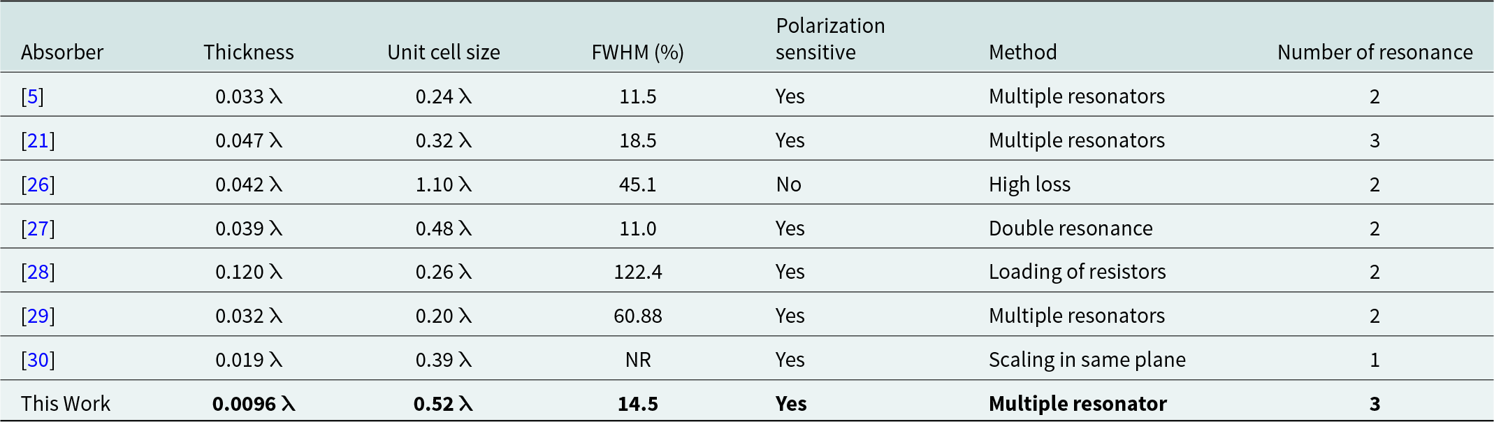
λ = Wavelength (= 31.77 mm) to lowest resonance frequency (9.44 GHz); NR = not reported; FWHM = full width at half maximum.
Conclusion
In this paper, a bandwidth-enhanced ultrathin polarization-insensitive frequency selective surface-based absorber has been presented based on multiple resonating structures. The resonating elements exhibit three distinct absorption peaks at 9.44, 10.00, and 10.53 GHz (all in X-band) with absorption magnitudes at 99.9%, 99.6%, and 95.1%, respectively. The absorption frequencies are realized in proximity such that they combinedly exhibit a broadband absorption response with an FWHM bandwidth of 1.48 GHz. In addition, the topology is polarization-independent as well as angularly stable for both TE and TM configurations. The absorption behavior has been examined by plotting the surface current and electric field distributions as well as presenting an equivalent circuit model and several parametric studies. Experimental verification of the fabricated prototype is also carried on to validate the simulated results. The geometry has been developed on an ultrathin substrate (0.0096 λ 0) with compact unit cell size and therefore, can be effectively flattened or bent on different non-planar surfaces, aiming for various shielding applications.
Acknowledgements
The authors acknowledge the support of Applied Electromagnetic Laboratory of IIT Indore for providing the testing and measurement facilities.
Funding statement
This research received no external funding.
Competing interests
The authors declare that they have no known competing financial interests or personal relationships that could have appeared to influence the work reported in this paper.

Gaurav Chaitanya completed his ME degree in Electronics and Communication Engineering from IES, IPS Academy, Indore (affiliated to RGPV, Bhopal, India) in 2012. He served as faculty for more than 16 years at Acropolis Institute of Technology and Research, Indore, India. Presently, he is a PhD research scholar at Indian Institute of Information Technology, Nagpur, India. He is Senior Member IEEE and Life Member ISTE. His research interest includes FSS, Metamaterial, and Absorber design.

Dr. Paritosh Peshwe received his ME degree in Microelectronics from BITS, Pilani in 2013 and PhD degree in Antenna Design from VNIT, Nagpur in 2019. His research interests include Antenna Design and Wireless Communication. Presently, he is working as an Assistant Professor in the Department of Electronics and Communication Engineering, Indian Institute of Information Technology, Nagpur. He is an IEEE member.

Dr. Saptarshi Ghosh completed his MTech and PhD degrees from Indian Institute of Technology, Kanpur in Electrical Engineering India in 2013 and 2017, respectively. He carried out his Postdoctoral Research Fellowship at Chung-Ang University, Seoul, Korea. Presently, he is working as an Assistant Professor in Department of Electrical Engineering at Indian Institute of Technology Indore, Madhya Pradesh, India. His research is primarily focused on electromagnetics, frequency selective surfaces, reconfigurable circuits, and metasurfaces. He has numerous referee positions in several IEEE Journals and Conferences. He is an IEEE member. He is an Associate Editor of IEEE Antennas and Wireless Propagation Letters.

Dr. Ashwin Kothari received his PhD from Visvesvaraya National Institute of Technology (VNIT), Nagpur in 2010. His research interests include Signal processing, Communication, Cognitive Radio, Rough Sets, Commbedded systems, and Antennas. Presently, he is working in the Department of Electronics and Communication Engineering VNIT, Nagpur as a Professor. He also served as an in-charge Dean at Indian Institute of Information Technology, Nagpur.



